Connecting a twisted pair cable to a connector. Correctly crimping the Internet cable
When crimping a network cable (twisted pair) and an 8p8c connector, you must follow the correct sequence (pinout, color scheme). If you crimp a network cable not according to the color scheme, then such a cable simply will not work.
– a special cable consisting of 4 pairs (8 cores) of wires. The connectors are usually 8-pin 8p8c connectors. These connectors are also known to many as RJ-45.
Such cables are used when creating a local network - connecting a computer with a router/hub or with another computer, and below I will show what types of pinouts there are.
Pinout
First of all, we need to decide for what purpose we need the cable and select the pinout. Network cables are designed to connect computers and network equipment to each other; two types of cable crimping are used:
- Straight
- Cross (cross)
A standard network cable is used to connect different types of network equipment and a computer, or simply to connect different types of network equipment to each other. The main condition when crimping such a cable is that the ends of the cable have the same sequence.
In the manufacture of such a cable, two crimping standards are used. The second option (B) is most often used - BO O BZ S BS Z BK K.
A crossover network cable is used to connect several computers to each other and in this case no additional network devices are involved. At the moment, it has lost its relevance, since many modern devices are able to determine the cable crimping method themselves and adapt to it (Auto MDI/MDI-X).
In addition to the network cable (twisted pair) and 8p8c connectors for crimping, you will also need a special tool (crimper).
It's okay if you don't succeed the first time. Usually the second and third time everything goes as it should.
According to the EIA/TIA-568 specification, there are several color schemes for crimping a twisted pair network cable (patch cord) into an RJ-45 connector to connect a computer to a router, hub, switch, or connect two computers to each other.
The power plug is usually called RJ-45, although its correct name is 8P8C. And RJ (Registered Jack) is the name of the standard that describes the design of the detachable connection between the plug and the socket.
All the photographs below show one cut UTP cable, intended for use in LAN (Local Area Network) and DSL (Digital Subscriber Line) networks, with twisted pairs crimped at its ends into RJ-45 plugs.
Color scheme for crimping RJ-45 computer - hub for the Internet
according to option B, the most common option.
Color marking for twisted pair lan cable crimping according to option A.
As you can see in the photo, in both versions the ends of the lan cable are crimped according to the same electrical circuit, only the two twisted pairs are swapped. Instead of the orange twisted pair, a green one is crimped, and in place of the green twisted pair, an orange one.
Twisted pairs of UTP cable, crimped according to both option A and option B, are mutually interchangeable . So you can crimp according to any color scheme you like, this will not affect the performance of the lan network.
Color scheme for crimping RJ-45 two pair twisted pair cables
Currently, a twisted pair network cable has appeared on sale, in which instead of the traditional four there are only two twisted pairs. And this is economically justified, since 90% of cable lines for the Internet use only two twisted pairs.
As you can see, the electrical circuit for connecting the RJ-45 pins has not changed, only instead of the green pair, the blue pair is crimped.
Such a twisted pair cable according to option B is crimped according to the diagram shown above in the photograph. When compressing according to option A, the pairs simply change places. Instead of an orange pair, a blue pair is crimped, and instead of a blue pair, an orange pair is crimped.
RJ-45 crimp color scheme computer - computer
If you need to create a local LAN network of two or more computers without the use of additional active equipment (hub, switch or router), for example, for group games, then for this case the EIA/TIA specification provides for the following twisted-pair network cable termination. To create a network of two computers, it is enough to insert one such twisted pair cable into their network ports.
Please note that the opposite ends of the computer-to-computer twisted pair lan cable are crimped in different color schemes.
Crimping RJ-45 twisted pairs is done with a tool called a crimping tool. If you don’t have pliers on hand, you can use twisted-pair crimping technology without pliers.
All the above color schemes for pinout of UTP twisted pair cables are currently losing relevance. Modern network cards, switches, hubs and routers, thanks to the support of Auto-MDIX technology, automatically detect the twisted pair cable crimp option and perform internal adjustments. So, when creating a network, a modern computer can be connected to either a hub or another computer without thinking about the color scheme of the twisted pair cable pinout.
RJ-45 crimp color scheme
according to PoE IEEE 802.3af and IEEE 802.3at standards
The IEEE 802.3af PoE standard provides the ability to transmit an information signal and supply power to the device via a single twisted pair cable crimped with an RJ-45 connector. This allows you to do without an additional wire to supply the supply voltage.
Regardless of the RJ-45 compression options, voltage is supplied simultaneously from the positive terminal of the power supply to pins 4 and 5 (blue pair), and from the negative terminal to pins 7 and 8 (brown pair).
As a rule, the pinout of twisted pair cables according to the PoE IEEE 802.3af standard is used when creating video surveillance systems that use a switch, for example, a 9-port PoE switch ROKA R-KM-POE0801, in which each port has the ability to feed via RJ-45 DC voltage 12 V with power up to 30 W.
RJ-45 4 wire crimp color scheme for Internet
When connecting a computer to the Internet or creating a local network, rarely does anyone use the full capabilities of twisted pair lan cables. This is usually due to a lack of information.
When transmitting a signal over twisted pairs of a CAT5 cable (speed up to 100 Mbit/s), only two pairs of wires are used out of the four available in the cable. One pair is for receiving a signal, the second is for transmitting, which is clearly demonstrated by the electrical diagram of connecting a computer network card using a twisted pair cable with an RJ-45 connector to a hub switch or router.
As can be seen from the diagram, each of the two pairs of lan cable is connected to a computer and a hub switch or router using a symmetrical transformer circuit. The advantage of the transformer circuit is that it suppresses noise and interference and provides a high degree of protection against short circuits and errors when installing twisted pair cables.
If it becomes necessary to lay an additional line or if pairs in a twisted-pair network cable are partially damaged, it is possible, without degrading the data transfer speed, to double the number of lines or repair the twisted-pair cable by crimping RJ-45 plugs onto previously unused twisted pairs.
The color schemes below for crimping an RJ-45 twisted pair cable do not differ from those shown above, but they show only the lan conductors of the twisted pair cable, which are used to transmit information. Twisted pairs that do not fit closely to the RJ45 plug are usually crimped, but no signal is transmitted through them and they can be used to transmit additional information.
Color scheme for crimping RJ-45 4 wires computer - hub
Twisted pair crimp, option B. The signal is transmitted only on the orange and green pairs.
Twisted pair crimping, option A. The signal is also transmitted only over green and orange pairs, but the twisted pairs are crimped into the RJ-45 plug to other contacts.
Color scheme for crimping RJ-45 4 wires computer - computer
Crimping twisted pair computer-to-computer. The signal is transmitted only on green and orange pairs.
What is the difference between a patch cord and a twisted pair cable?
A patch cord, or as it is also called a patch cord, is designed to connect electronic devices, for example, a computer with a hub, a switch, or two computers to each other if the devices need to be moved relative to each other during operation.
To make a patch cord, you take a twisted-pair cable, the cores of which are made of stranded wire so that they do not break due to frequent kinks. To crimp such a cable, special RJ-45 connectors are used. According to the ANSI EIA TIA 568B.1 standard, the length of the patch cord should not exceed five meters. Connecting devices using a patch cord is economically feasible if they will often move relative to each other during operation.
The RJ 45 (Registered Jack) connector, the most commonly used connector in the world used in any local area network, was developed in 1975 by Bell Labs to simplify the connection of network equipment.
Today we will look at various schemes for crimping the RG 45 patch cord by color onto a 4- or 8-core network cable, and we will tell you what types of connectors there are.
In essence, RJ 45 is a plastic cap in which 8 identical channels are made, separated by partitions. Above each of the channels there are so-called knives; they look like two sharp spikes; when crimping the cable, the crimping mechanism of the pliers presses forcefully on the connector knives, which in turn cut and fix the cable cores.
Types of connectors
Standard connector. A regular plastic connector is available for two types of cable: round and flat. As a rule, such a connector is intended for indoor use, since there is no protective rubber or vinyl cap, which means moisture ingress.
The same plastic connector, but on the base of which a rubber, vinyl or plastic cover is placed. For additional protection and convenience of corralling the connector cores, you can use a special seal.
Shielded patch cord. This connector is used to crimp a shielded FTP cable, which additionally protects against various interference and interference. For a UTP cable, such a connector is not necessary at all.
RJ 45 crimping diagram for 4 and 8 core cables
Many people are interested in the question - What is better than a 4- or 8-core twisted pair cable? Compressing two pairs of twisted (4 cores) pairs under the connector gives a network throughput of 100 Mb\s, which is sufficient for 98% of purposes and tasks. For example, an Internet provider installs either a 2-pair cable or a 4-pair cable into your apartment - there is no difference, since the network capacity that any Internet provider in Russia creates does not exceed 100 Mb\s.
A 4-pair cable is designed to work in gigabit networks, provided that all components on the network have a network card with such support, which is quite expensive. Example: copying a file at 100 Mb\s is 50% slower than on a 1000 Mb\s network.
Crimping 4-pair cable
Initially, there were 2 compression schemes according to the EIA/TIA standard - 568 B and EIA/TIA - 568 A. The first type was used to combine terminals or computers with a router, and the second type is also called “cross” for connecting routers to each other. Today, any router recognizes the type of connection at the software level, so the compression standard does not matter, the main thing is that the color pinouts at the two ends of the cable match.
Source: http://jolly-karaoke.ru/soedinenie-vitoi-pary-s-konnektorom-pravilno-obzhimaem-internet---kabel-kak/
How to properly connect wires to each other: terminals, caps, welding, soldering, crimping
Situations when it is necessary to connect or extend wires during the operation of electrical wiring occur in the following cases:
- If the electrical wiring is cut while drilling or tapping the walls.
- When moving sockets, switches and lamps without replacing power cables.
- If the length of the conductor in the installation or junction box after repeated re-wiring is not sufficient to connect it.
- Breaks in power cords of household appliances.
The correct way out of these situations is to replace the damaged section of electrical wiring or power cord. But as a temporary measure or in cases where replacing a section of wiring is not economically feasible, you can get by with making wire connections.
How to properly connect wires to each other in a wall
If you need to connect damaged electrical wiring in the wall of a panel house, then it is better to replace the damaged area with a new one. The conductors pass inside the cavities allocated for them and are not rigidly fixed.
Both ends of the damaged wire are found and disconnected. Then a new piece of wire is tied to one of them. The temporary connection is made securely and wrapped with electrical tape so that the edges do not cling to irregularities encountered along the way.
Pulling out the old wire, drag a new one in its place.
It is important that the material of the new conductor matches the material of the old one. If the wiring in the apartment is aluminum, then aluminum must also be used for replacement.
Instructions for connecting conductors in the wall
The connection of conductors in the wall is carried out as follows:
- We determine the direction of laying the damaged area.
- Turn off the power to the area being repaired.
- Along the axis of the cable laying, we cut the wallpaper to a length of 20 cm on both sides of the damage site. Use a spatula to remove the wallpaper from the wall and bend it to the sides. This will allow you to stick them back on after the repair.
- Using a hammer and chisel, we release the cable from the wall on both sides of the damage site by the same 20 cm. You can use a flat, dull screwdriver instead of a chisel. Do not apply strong impacts to avoid damaging the cable insulation.
- If one of the line conductors is damaged, separate it from the serviceable ones. To do this, we open the cable sheath or cut the flat wire (“noodles”) lengthwise. The core insulation should not be damaged, so be patient, careful and persistent.
- If all the wires are damaged, we cut the cable in both directions.
- We cut the cable cores into lengths depending on the chosen connection method. Connection by welding, soldering, crimping or using terminals is allowed.
- If the cable cores are made of copper, then when using ZVI terminals (also called nylon terminals), you will not need to insert a repair jumper. Having selected a terminal of the appropriate cross-section, use them to connect the ends of the wires.
- In other cases, you will need to install a repair insert. It uses wires of the same material and cross-section. There are two connections for each wire.
- Connections require sealing. If the wall is damp, touching it at the location of the uninsulated connection will result in an electric shock. Therefore, the contact point must be tightly wrapped with insulating tape, additionally placing heat-shrinkable or PVC tubes on the wires.
- We lay the wires in the groove and cover it with plaster. Until the solution has completely dried, voltage cannot be applied to the repaired cable due to the possibility of a short circuit.
- After the solution has completely dried, we paste the wallpaper back.
Features of conductor connection methods
A reliable connection method is welding . It uses a voltage of 12-36 V from a welding inverter or a homemade transformer. One wire (ground) is connected to the twisted wires, and the other to the carbon electrode. When the electrode touches the top of the twist, an arc occurs. It melts the wires and a metal ball appears at the end of the twist.
The result of connecting wires by welding
While reliable, welding also has a number of disadvantages :
- you will need equipment: a welding machine or a homemade transformer, a carbon electrode;
- difficulties with connecting aluminum conductors: aluminum is welded only in an environment of inert gases that prevent it from oxidizing.
The second most reliable permanent connection is soldering . But soldering aluminum is just as difficult as welding - you need special solder and flux. In air, this metal is covered with a film of oxides that appears instantly. Therefore, the principle of aluminum soldering is to dissolve the oxide and treat the wire in a flux environment.
There will also be difficulties when soldering old stranded wires. Each of their veins is covered with oxide, so before soldering you have to carefully scrape it off with a knife from all sides. It is better to tin it with solder fat; the use of rosin is ineffective.
Before soldering, the wires are thoroughly cleaned of oxides, dirt and soot. They are then twisted together and the resulting joint is tinned.
Solder connection
Soldering has a disadvantage - the connection is difficult to disassemble.
For crimp , connecting sleeves are used. These are thin-walled tubes of various diameters for connecting conductors of corresponding sections. The sleeves are made of copper or anodized (tinned), the latter are universal and connect copper and aluminum conductors.
The wire is inserted into the sleeve from one side to the middle, then pressed with special pliers or a press. Then another wire is inserted on the other side and pressed in as well. PVC tubes or heat shrink are first placed on the wires to insulate the connection. But fully insulated connection sleeves are also available.
Crimping twists with sleeves
The disadvantage of this method is that it requires a special crimping tool; pliers are not suitable for this.
The use of nylon terminals of the ZVI brand also poses difficulties when connecting aluminum conductors. Aluminum is a soft metal, and the connection in the terminal is made by pressing the wire against the brass surface with the end of a screw. The tightening force must be commensurate with the plasticity of the conductor, otherwise it can be cut. Flexible conductors are connected to the FVI only after tinning or termination with a sleeve tip (sleeve). But even in this case, you can’t push too hard.
ZVI terminals and their application
There is an opinion that if the conductors are twisted together and a wire connection is installed on top of the twist, the connection is reliable. But the terminal block screws, on the contrary, loosen the twist and worsen the contact. Therefore, the use of connections using nylon terminal blocks is functionally limited: you can temporarily connect or repair equipment with their help. Although in modern lamps the connection is made only through the ZVI.
There is only one advantage of the method: it is cheap.
WAGO self-clamping terminals are considered the most versatile means for making contact connections. No shortcomings have yet been discovered. The connection occurs through a spring-loaded contact into which the conductor is inserted. The terminal contains a lubricant that protects the wires from oxidation. If necessary, the connection can be disassembled.
About WAGO terminals, read the article: “Which is better to choose, twisted or terminal block for connecting wires?”
WAGO terminal
Another way to connect wires is with PPE caps (insulated connecting clamp). The cap is screwed onto the twist, tightening it and at the same time insulating it. Lubricant is also placed inside it.
PPE caps
For more information about PPE caps, read “PPE caps for twisting wires. Electrician's advice."
If WAGO terminals are selected according to the cross-section of the wires being connected, then PPE and ZVI are selected according to the diameter of the twist. And since the twists come in different cross-sections, depending on the number of wires in them, installation work requires a set of terminals of different calibers.
Source: http://electric-tolk.ru/kak-pravilno-soedinit-provoda-klemmy-kolpachki-svarka-pajka-opressovka/
Connection of large cross-section wires
The electrical circuit is located over the area of virtually the entire frame, providing the room with electricity for household and industrial appliances, depending on the purpose of the building.
Essentially, a cable is supplied from the central network, which is subsequently placed in the switchboard, from which several more come out, are routed to different ends of the room and connected to the distribution box, from where the final wires come out, ultimately connected to sockets, switches, etc. . Precisely in the distribution.
boxes create the largest number of connections, and sometimes a soldering iron, welding, or connectors are not used there, but wire twisting is used, which does not require special devices or tools, but only those things that virtually everyone has (knife, pliers).
How to properly twist wires
In order to virtually reduce the possibility of short circuits and ignitions, the twists in distribution boxes must be made with high quality. If a person performs such an action for the first time, it is better to first carefully read the rules of such a connection, and only after that begin to perform the work. Let's figure out how to do twists correctly, what types there are, and what problems you may encounter when performing this work.
https://www.youtube.com/watch?v=a2J-6t4Rfb0
To begin with, it is worth saying that connecting two wires of different metals by twisting is not recommended. Many analytical articles and arguments have been written about this as to why this should not be done:
- different coefficients of thermal expansion (metals react differently to heating and cooling, as a result of which the contact gradually deteriorates);
- the appearance of an oxide film on the aluminum wire (it does not allow current to fully flow, the wire heats up and breaks down over time);
- structural destruction of aluminum during electrolysis (these two metals form a galvanic couple, and after exposure to a humid environment, the metal ends are subject to heating and subsequent destruction).
Twisting of copper and aluminum wires
Copper and aluminum cannot be connected directly to each other. However, in many houses there are aluminum wires that need to be connected to copper wires, and twisting is sometimes the only way to connect. In this case, it is important to adhere to certain rules that will allow such fastening to last as long as possible.
- To begin with, it is worth noting that the conductors must be tightly wrapped around each other. If their diameter is significant, there must be at least 3 turns, and if the diameter is up to 1 mm, in this case it will be necessary to wrap the wire around each other more than five times to ensure high-quality transmission of electrical flow. Also, after this it is very important to treat the bare surface with a special varnish that is resistant to water and moisture.
- When connecting copper and aluminum wires, it is better to use a special steel plate placed between them. This will avoid their direct contact. Thus, the service life of such a connection will be much longer. If you don’t have such a component at hand, then you can resort to treating the bare copper wiring with solder, which will also avoid mechanical contacts of these two metals.
- The ideal solution for connecting copper and aluminum conductors is to first apply solder to the copper core. Especially such pre-treatment is often used when connecting single- and multi-core wires, when in this way a wire consisting of several conductors is converted into a single-core one.
Twisting wires of different sections
This type of work implies the unambiguous use of additional means for connection. Such devices can be screw clamps, self-clamping terminals, bolts, tinned copper lugs, and walnut-type holes. Also, in order not to purchase additional components, you can use soldering or welding, or other methods of connecting wires.
If the difference in the diameter of the wires is insignificant, for example, 4 and 2.5 mm, then connecting them by twisting is not so difficult. To do this, you need to carefully wrap them around each other, after which you need to use welding or soldering. This fastening of two conductors will last for many years without complaints.
In other cases, twisting wires will not be reliable and durable. In such situations, you simply cannot do without additional components. In various situations, certain devices are used:
- if the cross-section of the wires is large, it is best to use a self-clamping terminal;
- for branching from the main line to the distribution. The shield uses a branch compressor, which among experts is also called “Nut”;
- To connect wires with a large diameter, a copper-tind tip is used.
Errors when twisting wires
The most common problem with connecting conductors in this way is that one wire wraps around another. This is completely wrong. The wires must evenly wrap around each other, thereby ensuring reliable passage of electric current and creating mechanical strength so that such fastening will last for many years.
The length of the twist depends directly on the diameter of the conductors themselves. It is worth considering that the minimum threshold for this characteristic should be no less than 3 cm. Otherwise, everything depends on the diameter of the wires: the larger the diameter, the greater the length of the created twist should be, but there are no specifically prescribed standards in this regard, Each specialist decides for himself what this value should be in order for the connection to be reliable and of high quality.
Source: https://1000eletric.com/soedinenie-provodov-bolshogo-secheniya/
How to connect aluminum and aluminum wire together correctly?
When you need to connect 2 different sections of wire with each other, it is necessary, in addition to high-quality contact, to obtain sufficient strength of the section where these wires are connected to each other.
If we take into account the regulatory documents that are in force in our country, then it is permissible to connect aluminum wires to each other using various methods:
- Welding.
- Crimping.
- Soldering.
- Connection using terminals.
Despite the fact that all these connection methods specified in the regulatory documents are presented as universal, not all of them will be suitable when working with aluminum wires.
First of all, this is due to the characteristics of a material such as aluminum, in particular, its technical characteristics. As you know from a school chemistry course, there is always an oxide film on the surface of aluminum, formed as a result of direct contact with atmospheric oxygen.
It is not capable of conducting electric current through itself. In addition, the oxide film has a fairly high melting point - around 2000 degrees. This figure is significantly higher than the melting point of aluminum itself.
If you remove this film mechanically, it will appear again very quickly. It is worth noting that the presence of this film when soldering aluminum greatly interferes with the process of connecting the aluminum core to the solder. Also, it can cause difficulties when welding wires, because due to its presence various inclusions arise, due to which the quality of contact is greatly reduced.
Additional characteristics of a material such as aluminum include increased fragility and fluidity. In this regard, when connecting aluminum wires, care should be taken in advance to ensure that they are located so that the possibility of mechanical impact on this area is completely excluded.
It is worth noting that when connecting wires using a standard bolt clamp, it will have to be tightened periodically, since the metal will gradually flow out from under the bolt. As a result, the connection will become weaker.
Twist
Aluminum wires are often connected to each other using twisting. This is the simplest, but also the most dangerous method of connecting wires to each other.
The sequence of actions when using this technology will be as follows:
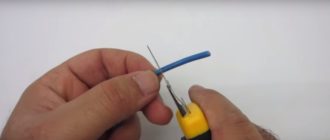
- First , remove the insulation from the wires approximately 4-5 cm on each side. It is most convenient to use a special tool designed specifically for this purpose.
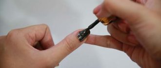
- Now the contacts should be degreased. To do this, you will have to wipe them with a cloth pre-moistened in acetone.
- Sandpaper is used to remove the oxide film from the surface of the metal, that is, to clean it until a metallic shine is obtained.
- The wires are crossed with each other , after which one of the wires is wound as tightly as possible onto the other using pliers.
- The second wire is wound onto the first in the same way.
- The twist should now be insulated using insulating tape. Professional electricians also recommend using a special heat-shrinkable tube or cambric. With its help, you can qualitatively protect the exposed area from the negative effects of the external environment.
In principle, the technology is quite simple. You just need to remember that the wires need to be exposed at least 4-5 cm, and the twisting should not be done manually, but only with the help of pliers, so that the wires fit as closely as possible to each other.
If this is not done, the result will be loose contact, which can cause the area to become very hot. In turn, this effect causes a short circuit, and in some cases even a fire.
Threaded connection
This type of connection can be very reliable if done correctly. It is worth noting that aluminum has the greatest linear expansion, and therefore a gap appears between the connected wires over time, worsening their contact with each other. To prevent short circuits, you need to tighten these screws from time to time.
To get rid of this need, special washers with cuts or groovers are installed. They select the resulting gaps and increase the reliability of the connection several times.
The wires will need to be wound around the screw so that the area of its contact with the contact pad is much larger. Professional electricians often do this: they flatten this ring on an anvil to increase the contact area.
The technology for making high-quality threaded connections of wires begins with removing the insulation from them to a distance equal to 4 screw diameters. The cleaned areas are degreased.
Then you need to bend their tips so that rings are formed.
The elements are put on the screw in the following sequence:
- Spring washer.
- Standard washer.
- Ring of the first wire.
- Another standard washer.
- Ring of the second wire.
- Screw.
This entire system is tightened until the spring washer is in a straightened state. In principle, if both wires are made of aluminum, then there is no need to place a standard washer between them.
We use terminal blocks
If aluminum wires have a low current load, they can be connected to each other using terminal blocks. Despite the fact that the appearance of such products may vary greatly, the principle of their operation is the same.
The body of the pads is made of plastic or carbolite. It contains tubes with thick walls made of brass. There are threaded holes on the sides. The wires to be connected are inserted into opposite ends and secured with screws. It should be noted that you can insert as many wires into one brass tube as will fit there.
This is not a very reliable connection compared to soldering, but installation work takes several times less time. In addition to connecting conductors made of the same material, it is permissible to use different wires in terminal blocks.
Permanent connection
If you do not plan to disassemble the wire connection in the future, you can use the so-called one-piece methods. These methods are among the most reliable. It is advisable to use them, first of all, in hard-to-reach places.
One of the easiest methods of permanent connections is crimping. To do this, take an aluminum tube of suitable diameter, twist the wires together, insert them into this tube and clamp them with press pliers. It is best here that the conductors fit as tightly as possible.
Only in this case will the connection be the most durable. It is worth noting: if the wires fit into the tube quite tightly, then you don’t even have to twist them together. At the last stage, the connection is isolated.
Today on sale you can find special tips for making this connection, which already have an insulating cap. It shrinks together with the tip and wraps around the wires, blocking any access to them.
To obtain a high-quality permanent connection, you need to have special pliers that will not bite, but only squeeze. If they are not available, then standard pliers will do just fine.
Soldering and welding
Soldering wires allows you to get a fairly high-quality and permanent connection. However, when connecting aluminum wires, you should be aware of the presence of an oxide film on them, due to which the solder will not adhere very well.
To prevent such a defect from occurring, you need to follow a certain sequence of actions:
- The connected sections of wires are treated with a special flux, which removes the oxide film from the surface.
- The solder is processed as carefully as possible so that it has the largest area of contact with the wires.
- When the connection area has cooled , it is advisable to treat it with sandpaper to remove sharp edges that could damage the insulating layer.
- Wires must be insulated.
Soldering requires certain skills.
It should be said that this method has several negative aspects:
- He has to be isolated.
- The method itself is quite complicated , especially if you have to solder wires under the ceiling while standing on a stepladder.
- If an error was made during the work , then correcting it will be quite problematic.
- A lot of time is spent on work.
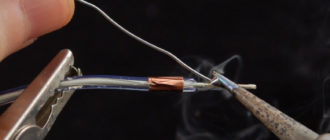
Welding is somewhat reminiscent of soldering wires, but it is much faster. In order to obtain a high-quality connection, the electrode is brought to the connection area for only 1-2 seconds. Both ends of the wire are pre-treated with flux to remove the oxide film.
If you have no experience in this area, then you should initially practice on twists prepared in advance, but not connected to the system.
After completing the welding process, the twists are treated with a special solvent and varnished.
The result is a high-quality connection that can last for a long period of time, since this method helps prevent overheating. Accordingly, such an area will need to be isolated.
Alternative options
flat spring clamp
The wires can be connected to each other using a rivet. In principle, this technology is similar to screw technology, only here a rivet is used instead of a screw. The end result is a permanent connection.
This connection is made quite simply: both conductors are put on the rivet through a spring washer, then it is inserted into the rivet gun and the handles are pulled together until a click is heard.
There is also a special flat spring clamp. Such products are disposable and reusable, when the wire can be either inserted or removed. However, it should be remembered that such clamps are made of plastic, so it is not advisable to use them for currents exceeding 10 A.
Working with them is very simple: the wires are stripped and inserted into the clamp until they click. It is impossible to pull them out from there without using a special lever. It is also advisable to insulate this section of the wire.
Connection Features
Aluminum wires are best placed in special junction boxes, to which they should be approached in corrugated sleeves. This is especially important when the installation is carried out outdoors or in the case of wiring in a damp room such as a bathroom.
In general, when connecting aluminum wires that will function outdoors, care must be taken to ensure that moisture does not approach the connection areas.
Otherwise, short circuit will not be avoided. In this case, it is very convenient to use the technology of welding wires, since the subsequent use of a special varnish eliminates the impact of water on the joint, and the insulating layer will additionally protect against electric shock.
Blitz tips
- Professional electricians do not recommend connecting aluminum and copper wires together. This is due to many reasons, the most important of which is the different resistance of metals. In addition, when interacting with each other, copper and aluminum oxidize very quickly, which causes heating of the wires and significantly worsens the contact. In addition, their rigidity is different, which significantly complicates the work.
- You can, if necessary, combine certain methods of connecting wires. In particular, twisting goes well with soldering or welding. The result is a very reliable and permanent contact that will last for a long time.
Source: https://housetronic.ru/electro/alyuminievyj-provod-soedinenie.html
Methods for connecting wires to each other
At first glance, there seems to be nothing unusual about the connection of the wires. I took it and twisted it for myself. Well, on the other hand, you need to know how to do it correctly.
How to properly connect or twist aluminum and copper wires?
First of all, it is necessary to connect wires only from one material; copper with copper, aluminum with aluminum.
But still, it very often happens that you simply need to connect a copper cable with an aluminum cable. The way out of this situation is to connect only through a special terminal block, so that the aluminum does not come into contact with copper, you will get a completely reliable and safe connection of copper with aluminum.
When using twists from different materials, at the junction of aluminum and copper cables, due to the different electrical conductivity of the materials, rapid oxidation occurs, as a result of which the current resistance increases and the junction becomes very hot. In the future, this can lead to melting of the wire insulation and a short circuit or its further fire. To prevent melting of the insulation on the twists, it is necessary to use rag insulating tape (textile), and not PVC.
Such heating can also occur if the twist is twisted incorrectly (weakly), as well as from exceeding the maximum passing load for a given cable cross-section through this twist.
If it is necessary to make connections using twists, all twists must be securely twisted, the wires must be cleaned with a knife or sandpaper to remove dark deposits (oxide), this will greatly improve the electrical conductivity between the connections.
The twist length should be at least 40-50mm. The best option for twisting copper wires is soldering with a soldering iron, using rosin, not acid, as it oxidizes the connection and significantly reduces contact.
To eliminate the problem of reliable connection, as well as connecting copper to aluminum, we recommend using connections on quick-release terminal blocks from WAGO (Germany). To connect, you need to strip the wires by about 10-15 mm and insert them tightly into the holes of the terminal block.
Wago terminal blocks are used for different sections and types of wire, and can also be used to simultaneously connect copper and aluminum wires. Inside, the terminal blocks are filled with a special lubricant that improves electrical conductivity and prevents the wires from oxidizing.
It is advisable to use terminal blocks in any connections.
One of the old and proven methods of connecting wires made of various materials is with the help of untwisting clamps, popularly known as “nuts”.
The branch clamp consists of 3 metal plates, between which the wires are clamped. The advantage of this connection is that there is no need to break the line to connect the outlet wire. The outgoing wire is inserted between the middle and last plate.
Another fairly common method of connection is on screw terminal blocks. In this case, you just need to insert them into the hole in the terminal block and tighten the screw. This connection also makes it possible to connect wires made of different materials.
To connect flexible (multi-wire) wires (PVS, PUGNP, SHVVP, KG, etc.) through screw terminal blocks, so that the screws do not cut the wires, it is necessary to solder them, but no one likes to do this, so in order not to solder the ends of the wires, you need use crimping sleeves to prevent the wires from spreading in the terminal.
If you liked the information on this page, you can recommend it on the Internet by clicking one or more bookmark buttons at the bottom of the panel.
How to connect the wires correctly?
In this article I will try to take a closer look at how to connect wires. The quality of wiring depends on almost 90% of success.
What's the use of rewiring a house if the wiring in the junction boxes is so bad. There are many consequences. Incorrect operation of safety devices. Heating at the terminals and damage to the cable. Or even fire. To avoid such consequences, the wires must be connected correctly. The PUE (rules for installing electrical installations) in paragraph 2.1.21 of Chapter 2 provides for:
The connection is live branch and termination cables and must be made by cutting, welding, softening or pressing (screw, screw, etc.) in accordance with instructions that have been appropriately approved.
Remember!
Twisting the cold wire is PROHIBITED
Squeezing the wire, as you understand from the title, prepares the seal. Mechanical presses are usually for cross sections from 1.5 mm2 to 35 mm2 and hydraulic for cross sections up to 240 mm2 and more.
When connecting this method, it is necessary to select the correct section of sleeves or tips, as well as the print matrix. With the right approach, we get a very reliable and long-lasting connection.
There is only one minus. Such a connection is impossible.
Tips we use with PGR-70.
The method is completely new. This requires a welding machine such as TES-700 and a carbon electrode. When all the wires are connected in the roll, touch the carbon electrode of the tip and hold until a copper ball forms. In this regard, there is virtually no contact resistance. One more addition can be added so that such a connection can be easily dismantled.
It's enough that you bite the ball at the end of the throw and you can unscrew the wires. You can write down the costs of the welding machine and the problems with welding at height (on a ladder below the ceiling).
The most affordable way.
A 60W-80W soldering iron can be purchased at an electrical goods store. Experience shows that this is the optimal force for such work. Less - do not heat the wires. More - wire wires work. Don't forget about dew and tin. Instead of rosin we will use a special stream. Live on a roll and solder carefully. The connection will last a very long time. The only drawback is that if the turn is long, then control in the junction box is problematic.
This link is barely bent.
This word means Wago, PPE, ZVI staples.
We will pay special attention to them.
They appear on the market and immediately take their rightful place in the electrical box.
Easy to assemble units. Terminals from 2-pin to 8. In principle, a self-locking device is installed. The insert will not work when the wire is removed. Just secure the wire from 1.5mm2 to 2.5mm2.
There is a wago model that has a 4 mm2 cable section.
Among the shortcomings, I see the continuity of the connection and a small current of 24A. Therefore, you are better off using them in room lighting lines. At the time of writing, the cables are sold in multi-core cables.
They can be reused, which allows you to expand the scope.
These “caps” are often used when installing electrical wiring. Comfortable. Tighten the threads on the last package. It turned out to be a simple removable link. Only if you decide to add wire will you need to replace the PPE with a larger one.
They are also called tape or shoes. They are sold in packs of 10. Sections vary greatly from 0.75 mm2 to 16 mm2.
Just cut off the number of links you need. Insert the wires on both sides and tighten with the screw. It is not recommended to insert one wire on each side.
It is suitable for lithium body wires and multi-wire cable (flexible), as long as the grommet clamp is compressed. And don't forget this link once a year.
Leave a reply
Sergey
Wire welding: -New meta. I don't agree that my grandfather could say that.
PPE: -They are brought into full rotation. Even here, unfortunately, you are not justified, only the PPK spider should be created: - We will come to special flows.
Only if it is neutral colophon based, otherwise it should be washed. ADMIN: Thank you for your criticism! I didn't know about PPE (because I don't use it)! You're right about that. It should be used only based on rosin without adding acids.
Salim
I would like to make a statement to my colleague regarding the PPE. I support the PPE that would fool the finished shrapka. While going through the power wiring I noticed that the connections are twisted SIZom Iskra, which means it turns. SIZom does not provide sufficient contact around all the cables that are in the bundle and, of course, depends on the load of consumers
svarkagid.com
Welding consists of several technological processes.
First remove the covering and insulation from the wires, then turn. The resulting roll is cut so that the ends of all wires are at the same level, and the twist length is at least 50 mm.
bright
Monitoring is not delayed with PPE. And rightly so!
From experience: cold wraps 5-7 cm long are more secure than buckles. Twists that have been under the tape for 20 years work great - without frying or breaking. But personal personal fuses are weakened and burned out after six months or a year.
Konstantin
useful information
Alexander
There is no soldering or soldering in the photo, the connection does not heat up, and the contact is not reliable
HectorCroli
Source: https://stroitel12.ru/sposoby-soedinenija-provodov-mezhdu-soboj/
How to connect a television cable to each other correctly?
08.04.2019
Do you still watch TV? Despite the increasing popularity and accessibility of the Internet, the share of television viewers in Russia is not decreasing. The expansion of thematic channels has led to the individualization of preferences - everyone can now find a program to suit their taste. But what to do if the antenna cable was chewed by a dog or you bought another TV to install in the next room?
The reason for the need to connect the antenna cable may also be redevelopment in the room, when you need to add the missing length. There are several ways to accomplish this: using F-connectors or a splitter, soldering or twisting contacts. I will tell you each of the sounded methods with the nuances of their application. Don't switch!
How to extend a TV cable?
Radio mechanics identify the following options for connecting and extending the antenna cable:
- F-connectors are a special metal structure that allows you to reliably connect two pieces of cable without the use of a soldering iron or additional insulation. The method is often used when, when moving the TV to the other end of the room, the available supply of cable is not enough or the damaged section needs to be replaced. This is the simplest and most economical method, as opposed to laying a new cable directly from the antenna.
f-jack connector for coaxial cable
- Splitter - used to evenly divide the signal coming from the antenna into two TVs. Connection to the device is made using F-plugs.
Splitter for F-connector
- Soldering is a cheap but at the same time reliable connection method. To implement it, you do not need to look for adapters and other components; usually everything you need is already available at home. It is possible to connect any shielded cables: with a different number of central cores, diameter, type of screen (for example, copper braid and aluminum foil).
Soldering the antenna wire
- Twisting is the least preferable method of all presented, since it leads to a strong loss of signal quality. Due to its unreliability, it can only be considered as a temporary solution, in the absence of F-connectors or soldering tools.
Next, we will look at the practical application of each described method of connecting an antenna cable.
With the transition of analogue broadcasting to digital form, the requirement of televisions for the broadcast signal has increased. Residents of suburbs and villages now use TV tuners with amplifiers. Therefore, the quality of the connection of television wires came to the fore.
Extension of TV cable using F-connectors
This option for connecting the wire involves visiting a store where you need to purchase two F-plugs (for each of the 2 ends of the cable) and one adapter - F-socket. It is recommended to take a piece of TV cable with you, since components are sold for different diameters. The tools you will need are a regular or construction (segment) knife and wire cutters.
Extension with a plug does not create interference
Building up an antenna cable begins with preparing its sections:
- Make a careful cut into the outer shell. For ease of operation, the length of the cut should be greater than the length of the F-plug body. In the future, it can be adjusted by removing the excess part of the central core.
- Fold the casing in the opposite direction and remove it completely.
- Turn the copper shield and the foil underneath towards the remaining outer shell. To perform the procedure, they can be slightly incised. At this stage, pay attention to the possible presence of a coating of a thin layer of polyethylene or lavsan on the inside of the foil. These materials greatly impair the transfer of contact to the F-plug housing. To solve the problem, screw back half of the wrapped foil. This way the side with poor current transmission will be on the inside.
- Using a sharp knife, cut the insulation of the central core. Try not to leave notches on it, as they reduce strength and can lead to breakage.
- Take the F-plug and screw it onto the cable. It must fit snugly, since the fixation is achieved only by clamping force.
- Trim off any excess center core. Its edge should protrude 3-5 mm beyond the F-plug body.
If the diameter of the cable is smaller than the internal diameter of the F-plug, then before turning off the screen with foil, wrap electrical tape around the outer sheath.
Sample connection via adapter and f-plugs
This completes the preparation of the two ends of the cable. Now take the F-socket and connect the first and second plug to it. Fixation is ensured by screwing the movable head of the F-connector onto the thread of the adapter. The result will be a neat and reliable connection. In its place, you can also install a splitter, which will be discussed later.
Extending the cable using a splitter
This device is designed to distribute the input signal evenly. Accordingly, it has one incoming connector (labeled with the word “IN”) and several output connectors (labeled with “OUT”). Using a splitter, you can not only extend the cable, but also route it to two or three TVs at once.
The inlet hole on the splitter itself is similar in principle to the F-socket. Fixation occurs due to a threaded connection. The process of extending the cable is similar to that described for F-connectors, so there is no point in dwelling on it separately.
You can connect several TVs through a splitter
Connecting TV wires by soldering
For this method you will need a soldering iron, solder and rosin (an alternative is soldering acid). You should also have basic soldering skills.
The method allows you to connect different cable variations. Let's consider step by step the process of soldering two cables with a single core and a double screen (copper braid + aluminum foil):
- On each cable, make a cut along the outer sheath 5-6 cm long.
- Unscrew the shell and the screens underneath it - copper mesh and foil.
- Cut the central core along with the insulation to a length of 2 cm.
- Cut off part of the insulation from the central core - the result will be some kind of step. When folding two parts of the cable, this design should ensure complete closure of the contact, with virtually no gaps.
- Bend the central core away from the insulation by 45 degrees. Tin it and solder it to the second part of the wire. In the absence of an assistant, before soldering, the cores can be tied with thin wire taken from a copper screen.
- Inspect the soldering results. If the cured solder has sharp edges or beads, remove them using fine-grit sandpaper or a file.
- Close the two steps cut from the insulation together, removing excess if necessary. Secure the resulting structure with insulating tape - 2-3 turns.
- Replace the foil on the two parts of the cable. On the inside it is covered with a non-conducting layer, so you need to properly wrap this part of the screen, ensuring contact between the conductive sides.
- Return the copper mesh - first one, then the other. To improve contact, wrap the area with several pieces of tinned wire of the same diameter. Then solder these parts.
- Unscrew the outer shell one by one. As a result, one should envelop the other. Secure the connection with insulating tape.
At the output, you will get a durable and sealed junction, which has virtually no effect on the quality of signal transmission.
Of course, soldering is stupid. There are no problems with the central copper core, but the braid is usually made of aluminum alloy, which is almost impossible to solder.
But if you really need it, the recipe is this: wind several turns of tinned wire onto pre-twisted braided pieces. Tin this area and, after cooling, flatten it with a hammer.
I recommend using the SAT-703 cable from the Italian company “CAVEL” with a linear attenuation of 16.5 dB/100 m. The central core is copper. Braid - tinned copper. In this case, both conductors are soldered with ordinary rosin.
Twisting method
Use this option only as a last resort, when you need to immediately provide a signal to the TV, and you don’t have F-connectors or a soldering iron with solder at hand. Twisting in any case will lead to a significant loss of signal quality, and during the connection of the central core it often breaks.
In general terms, the twisting technique is similar to soldering. You will need to prepare the two ends of the cable in a similar way, then fold them parallel to each other. First, twist the copper mesh and insulate the area with PVC tape. Then the central cores are connected. Considering the temporary nature of the work and the good insulation of the copper screen, the cores can be left as is - bending them to the outer braid is fraught with a break.
Twisting is a simple and unreliable connection method
These are all methods that can be used to extend the antenna cable.
The simplest option is to use F-connectors - they are not expensive and do not require special tools for installation. I recommend soldering when connecting two wires with different characteristics.
To branch the signal to several TVs, use a splitter. Twisting is a temporary method that should be replaced with a more reliable one in the future.
How to properly connect a television cable to each other: splitter, f-connectors, twisting and soldering Link to main publication
Source: https://zulkinoks.ru/sdelay-sam/kak-soedinit-televizionnyy-kabel.html
How to properly connect aluminum wires to each other? — Website about
Connection of aluminum wires
How to connect two aluminum wires to each other? It would seem like a rather banal question, but even here the first answer that comes to mind is not always correct. After all, twisting of wires is prohibited according to the PUE standards, and any wires can be connected only by crimping, soldering, welding and using screw clamps. And we’ll talk about how to do it correctly in our article.
Properties of aluminum wires
But we propose to start our conversation with a quick analysis of the properties of aluminum wire. This will allow you to identify problem areas and understand possible problems during its installation.
Comparison of copper and aluminum wire
- Let's start with the advantages of aluminum wire. The main one is the price, which is an order of magnitude lower than that of its main competitor - copper.
- Another advantage of this material is its lightness. This has led to its widespread use in power lines, where weight is very important.
- Well, the last advantage is its resistance to corrosion. Aluminum is almost instantly coated with a persistent oxide film, which prevents further oxidation. At the same time, this film also has negative aspects - it is a very poor conductor of electric current.
Areas of application of copper and aluminum wires
- Then there were only continuous shortcomings. And the first of them is the low electrical conductivity of aluminum. For this material it is 38×106 S/m. For comparison, for copper this parameter is 59.5 × 10⁶ S/m. This results in the fact that, for example, a copper wire with a cross-section of 1 mm2 is capable of passing a current almost 2 times greater than a similar aluminum wire.
Resistance of some substances
- The next significant disadvantage is that aluminum wires have very low flexibility. In this regard, they cannot be used in places where the wiring is subject to repeated bending or other mechanical stress during operation.
- Well, and finally, the instructions say that aluminum has such a bad property as fluidity. As a result of thermal and mechanical influences, it can lose its shape, which has an extremely negative effect on contact connections.
Note! According to the PUE standards, since 2001 it has been prohibited to use aluminum wire for installing electrical wiring in residential premises. This ban significantly reduced the use of aluminum electrical wiring in everyday life.
Methods for connecting aluminum wires
As we said above, aluminum wires can be connected in four main ways - screw or bolt clamps, pressing, welding and soldering. Let's look at the features of each of these types of connections.
Connecting aluminum wires using the compression method
Let's start with the most common connection method - compression. It can be of several types - bolted, screw or using a pressure spring, which is used in Wago terminals.
| The screw terminal may damage the aluminum wire | Connecting aluminum wires to each other using this type of connection has one drawback. If you use conventional screw terminals, then using a screw you can completely or partially press down the soft aluminum core. This will either reduce or completely destroy contact. |
| Brass lugs for aluminum wires | To exclude this option, the connection should be made through special contact nozzles made of brass. Brass has less elasticity and is more difficult to bend. Therefore, such attachments provide reliable contact and eliminate the possibility of damage to the wire. |
| Aluminum lugs for bolting wires and cables | For bolted connections of aluminum wire, special lugs should also be used. They are attached to a wire or cable using the crimping method and then these lugs are connected using a bolted method. |
| Wago terminals for connecting aluminum wires | As for Wago terminals, everything is much simpler here. This type of connection cannot damage the wire, so such terminal blocks can be used without additional attachments. This somewhat compensates for their higher price. |
Connecting aluminum wires using the pressing method
Recently, connecting aluminum wires with a sleeve has become increasingly popular. This is partly due to the widespread use of crimpers or, as they are also called, crimping pliers. This tool allows you to crimp wires of different sections, ensuring fairly reliable contact.
Crimpers for crimping wires
Sleeves for connecting aluminum wires
- The connection of wires by crimping is carried out using special sleeves. These sleeves are available in different diameters and materials. To connect aluminum wires, either aluminum or brass sleeves should be used. Copper should not be used under any circumstances, since the connection of these two materials can lead to the formation of galvanic isolation and ultimately the complete destruction of the aluminum conductor.
Note! The cross-section of the sleeve for connecting wires must correspond to the cross-section of the wire.
https://www.youtube.com/watch?v=tRHLv23JFv4
If you use a sleeve with a smaller cross-section, then to insert the wire into the sleeve you will have to reduce its cross-section, which will negatively affect the contact.
If you use a sleeve with a larger cross-section than the wire, then the area of the contact connection will be much smaller, which again will lead to overheating of the contact.
Sleeves for connecting wires of different sections
- To connect wires of different sections, there are sleeves with different diameters of the inlet holes. They can also be used to connect more than two wires in one sleeve.
- Sleeves for connecting aluminum wires have a strictly required length. Believe me, the manufacturer did not make a reserve in the sleeve, so cutting the sleeve in half in order to save money is a very bad option. After all, when connecting two wires, crimping should be done twice with opposite crimps. If you cut the sleeve in half, you won't be able to do this, and the contact will be poor quality.
- Another frequently asked question relates to connections between stranded aluminum wire and solid wire. It is possible to make such a connection using crimping, and it will be of sufficient quality. The main thing is to choose a sleeve with the appropriate inlet diameters. Indeed, in most cases these are wires of different sections.
Connecting aluminum wires welding method
The best quality of connection is ensured by welding. Due to the fact that in this case the wire forms a single whole, problems with transition resistances, the possibility of reducing the pressure force, and much more are practically eliminated. But there are also a lot of problems here.
Welding aluminum wires
- The fact is that, as we said above, an oxide film forms on the surface of aluminum. It has completely different heat and electrical conductivity than aluminum itself. In this regard, welding aluminum wires is difficult.
- Since the melting temperatures of oxide and aluminum differ, attempts to simply weld wires with a carbon electrode will not be very successful. Oxides will remain on the molten drops of aluminum, and the compound itself will not be homogeneous, as in the video.
The photo shows the process of welding aluminum wires
- To eliminate this problem, you can remove oxides from the surface mechanically, but this is labor-intensive and not always effective, since the formation of a new film occurs almost instantly.
- Based on this, in most cases, various fluxes are used for welding, which can destroy the oxide film. This material should destroy the oxide film and practically not react to pure metal; in addition, it should not produce harmful compounds during welding. Selecting such material is quite difficult and often you have to make a compromise.
Wire welding technology
- But even with the use of fluxes, it is quite difficult to make a welded connection of wires with your own hands without proper preparation. This is due to the fact that it is extremely important to select the proper welding voltage (usually no more than 20V) and exposure time to the conductor (usually 1-2 seconds).
Note! In addition to electric welding of aluminum wires, gas welding is also quite common. It has its own characteristics regarding both the materials used and the welding temperature.
Connecting aluminum conductors by soldering
The last option that can be used to connect sockets with aluminum wires is soldering. This method is quite labor-intensive and can hardly be called fast.
Therefore, it is used extremely rarely for power plants, and in low-voltage networks, aluminum wires are used quite rarely due to their rigidity. Nevertheless, let's consider this option.
Soldering aluminum wires
- The main problem here, as in the case of welding, is the oxide film. In addition, there is such a problem as the lack of visual control over the temperature of the wire. Indeed, with prolonged exposure to high temperatures, aluminum can change its physicochemical properties.
- Based on this, the process of soldering aluminum becomes quite complex. First of all, we need to get rid of the oxide on its surface. This can be done using any abrasive materials, but you should not be zealous, since a new film is formed almost instantly. Our task is only to reduce its thickness.
- After this, the wires are fixed and solder and flux are touched to the wires. It is better to use TsOP-40 or its analogues as solder.
- Flux for soldering aluminum is F - 59A, F - 61, F - 34 or other similar compositions. They destroy the oxide film quite well.
Solder for soldering aluminum
- When the solder touches the wires, they should be scraped across them to make it easier for the flux to break down the oxide film. If soldering is performed without using flux, then the intensity of friction of the solder on the wires should be more intense.
Conclusion
Connecting aluminum wire with a sleeve and using terminals are the simplest options. At the same time, the use of crimping does not require additional materials, but requires the presence of a crimper.
The use of pliers and other auxiliary tools may affect the quality of the connection, so their use is unacceptable. However, when comparing price and quality, the crimping method is one of the best for connecting aluminum wires.
Source: https://orensbyt.ru/elektrooborudovanie/kak-pravilno-soedinit-alyuminievye-provoda-mezhdu-soboj.html