How to Read Automotive Wiring Diagrams
Failure of the electronic components of a modern car can lead to its complete immobilization . It’s good if this happened near your home or work, but if this happens on the highway or in nature, such a breakdown can cost you extremely dearly: both in terms of money, and in terms of lost time and even (I hope it doesn’t come to that) health !
Why is it useful to understand auto electrics?
Even if you are not technically minded or your income allows you not to think about such mundane details, replacing a regular blown fuse on a long journey will make your life much easier.
I'm not even talking about those cases when servicemen, not wanting to understand the problem of your car, urge you to change all the sensors in a row, spending significant amounts of money on this “carousel” (which, by the way, sometimes does not guarantee a positive result).
Therefore, I suggest that you do not give up ahead of time and try to independently diagnose the breakdown of your car, and for this it would be nice to have electrical diagrams on hand, and most importantly, be able to read and understand them.
Electrical circuits? - even a schoolboy can figure it out!
When I first encountered a schematic electrical diagram of a car, I realized that the principles of its construction and the designation of elements on it are standardized, and those elements that are present in all cars are designated the same way, regardless of the car manufacturer. It is enough to figure out once how to read such electrical diagrams, and you can easily understand what is shown on it, even if this is the first time you have seen a specific diagram from a specific car and have never even climbed under the hood of it.
Graphic designations of circuit elements may differ slightly; in addition, there are black and white and color versions. But the letter designation is the same everywhere. In addition to schematic electrical diagrams, it is useful to have diagrams that indicate the physical location (in space) on the body of various harnesses, connectors and grounding points - this will help you quickly find them. So, let's take a look at examples of such circuits, and then proceed to describe their elements.
An example of a car electrical circuit diagram
The circuit diagram does not indicate the physical relative positions of the elements, but only shows how these elements are connected to each other. It is important to understand that if two elements on such a diagram are shown next to each other, on the body itself they can be in completely different places.
Schematic arrangement of electrical components on the body
Such a diagram carries another type of information: the routing of the cable braids and the approximate location of the connectors on the body.
Three-dimensional accurate diagram of the location of electrical components of the car
There are also diagrams that show exactly how and where the cable routes go in the car body, as well as grounding points.
Standard elements of a car circuit diagram
Let us finally begin to examine the elements of the diagram and learn how to read it.
Standard power circuits and connection of elements
Power circuits - circuit elements that transmit current, are depicted by lines: at the top of the diagram there are circuits with a positive potential (“plus” of the battery), and at the bottom - with a zero potential, i.e. ground (or battery negative).
Circuit 30 - comes from the positive terminal of the battery, 15 - from the battery through the ignition switch - “Ignition 1” Circuit number 31 - grounding
Some wires also have a digital designation at the point of connection to the device; this digital designation allows you to determine where it comes from without tracing the circuit. These designations are combined in the DIN 72552 (frequently used values):
For convenience, connections between elements on color diagrams are depicted in different colors corresponding to the colors of the wires, and on some diagrams the wire cross-section is also indicated. On black and white diagrams, the colors of the connections are indicated by letters:
Sometimes you can find an empty circle in a node - this means that this connection depends on the configuration of the car, and the lines are usually signed.
Designation of connectors on the electrical diagram - connectors
Pin No. 2 of connector C301 is connected to pin No. 9 of connector C104, which, in turn, goes to pin No. 3 of connector C107
Wires in car wiring are connected in several ways, and one of them is connectors.
The connectors are designated by the letter “C” and a serial number. In the figure on the left you see a schematic representation of the connections of sections of wire through connectors.
In general, it is more correct to say not “pin No. 2”, but “terminal No. 2”; if you come across such a concept in the diagram, then now you will know that this is the serial number of the connection (contact) in the connector.
Well, in this figure you can see how the contacts in the connectors are numbered and how to count them correctly in order to find out which pin is which. Contacts are numbered from the “mother” side from the upper corner from left to right line by line. From the “dad’s” side, accordingly, it is mirrored.
By the way, for some reason, on many forums, car connectors are called “tricks”; there is no information on this “etymology” on Google. If you know or guess where this name came from, write in the comments, don’t be shy.
Source: http://artsybashev.ru/cardriver/kak-chitat-elektricheskie-shemi-avtomobilya/
How to properly connect (install) a radio in a car and a diagram for connecting a tape recorder according to the colors of the wires to the car
Connecting the radio and installing it can be done in different ways. This procedure will not cause any particular difficulties.
How to install a car radio
Installation of a car radio is most often carried out in a standard place on the front panel of the car. Otherwise, installation of the radio is done using a special mount that you can make yourself. Since 1 DIN radios are the most common, the seats have a height suitable for installing these devices. For 2 DIN sizes, additional modifications to the dashboard will be required to install a player in the car.
You should check the package contents of the device before installing the car radio to make sure you have all the necessary parts.
Installation of the standard radio is done using a special frame that is included with the device. It is used to fix the radio in the car. First, the box for small items is removed, which is located in the standard place for installation. Then the metal frame is inserted.
Using the supplied special tool, pick up and bend the fixing tabs.
The next stage of installing a car radio with your own hands is securing it to the seat. Some devices have a threaded hole on the back wall. A pin is screwed into it, with which you can further secure the player. To do this, attach a special strip to the back of the dashboard.
To install a non-standard radio, you will need to check which mount is used and whether it fits the seat. If there are threaded holes on the side walls of the device, then installation of the radio on the car is carried out by screwing it to the dashboard with bolts.
How to properly connect a car radio
Connecting the car radio is done in several ways:
- Using an ISO connector.
- Without using chips by splicing wires.
- By directly connecting the power wires to the battery terminals.
- Via the ignition switch or a separate switch.
- Through a security alarm.
Car radio diagrams, which help with the correct connection, are printed on a label on the top cover of the device. They indicate the color marking of the wires established by the generally accepted standard:
- red - power management;
- yellow - power supply to memory and amplifier;
- black - mass;
- blue with a white stripe - power supply to the antenna with amplifier.
For reliable fixation, the wiring can be secured using cable ties.
Connection with and without chip
The first option for connecting the radio to the car is suitable if you have an ISO connector, which is built into recently released devices. If the tape recorder is equipped with a proprietary connector, then you need to purchase an adapter suitable for it, which may or may not be equipped with an additional feature. In the first case, if there is a mating part in the car wiring, the connectors are inserted into each other.
In the event that the proprietary adapter or the radio itself does not have a chip, the cable is connected by twisting or soldering the wires. The last connection option without a chip guarantees a more reliable connection.
The car radio circuit determines the purpose of the wires by color and the presence of additional contacts. Some car video players have a parking line. It connects to the parking brake button.
This feature allows you to watch movies in the car while the handbrake is on.
Direct to battery
This connection method is applicable for high-output radios equipped with a subwoofer, when the capacity of the ignition switch contacts becomes insufficient for reliable operation of the device.
This method is also used in the case when, when passing through the “Off” position. The ignition switch de-energizes all consumers connected to it, as on domestic cars.
The cable connected to the battery must have a thickness of at least 3 square meters. mm.
First, the cables are laid in the engine compartment away from hot and rotating parts. To install the wires under the dashboard of the car, use the existing hole, which, after installing the radio, is sealed to protect it from precipitation.
To connect to the battery terminals, a nut is unscrewed on each of them, after which the stripped end of the wire from the radio is inserted under the bolt, put in place and screwed.
The attachment point is treated with WD-40 to protect against corrosion.
In accordance with the connection diagram of the radio, the plus from the battery is connected to the red and yellow wires, the minus to the black. A fuse with a rating of at least 10 A is inserted into the positive wire. It provides additional protection against short circuits and overloads.
Through the ignition switch
Connecting the radio in the car through the ignition switch allows you to avoid premature battery discharge during long-term parking by disconnecting the yellow wire of the radio, which is responsible for power supply during operation of the device. The red wire of the radio is connected to a DC power source.
The yellow wire, according to the car radio connection diagram, is screwed to the ignition switch terminal, which is energized in the “Ignition on” key position. This can be determined by a control lamp. With this method, you can use the radio only when the ignition is on. Otherwise, the functionality of the device is limited to clock operation, CD ejection, etc.
Through a button instead of the ignition switch
You can also connect the radio in your car via a button. It can be used to turn off the power supply to the red wire if the audio device is not used for a long time to avoid quickly draining the battery - just like through the ignition switch. The button, which must be locked in the on position, is installed in the free space on the dashboard provided by the car manufacturer.
To connect the radio via a button, one of its terminals is connected to any wire in the on-board network that carries the “plus”, the other to the red wire of the device. For it to work, you need to press the button. When leaving the car for a long time, you should turn off the power using the toggle switch.
Via alarm
Using this method, you can make a mechanically controlled car radio turn on when the alarm goes off if the standard siren fails. To properly connect the radio, you will need an additional relay. Its winding is connected to the terminals intended for connecting the siren. Through the relay contacts, the radio is connected to a power source.
After all connections, the volume control is turned to the maximum position. If the alarm goes off, the tape recorder will start playing the recording loudly. To use the radio in standard mode, you must install an additional switch. The first terminal is connected to the positive terminal of the battery, the second to the radio wire. Before starting listening, a comfortable sound level is set.
Source: https://AutoTuning.expert/magnitola/podklyuchenie-shema.html
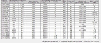
How to choose wires for car wiring - review of brands, prices, characteristics
In the process of selecting wires that are used for installing automotive wiring, it is extremely important to take into account the key factors of the influence of the external environment on them.
During operation, vehicle lines will be subject to vibration, become contaminated with fuel and engine oils, and also operate under conditions of temperature fluctuations.
That is why the insulating layer of a car wire must be resistant to aggressive environments and withstand both frost and abnormally high heat. Another criterion by which auto wiring is selected is ease of installation, that is, a sufficient indicator of flexibility.
Review of the most popular brands of automotive wires
Below we present the main technical parameters and characteristics that distinguish automobile lines produced by domestic manufacturers:
PVA brand
PVA belongs to low-voltage cables and has a high 5th class of flexibility. This brand is specially designed for use in the industrial production of automobiles. PVA perfectly withstands heating up to +105 C, while the maximum operating temperature can reach +135 C, but not more than 96 hours. The brand withstands the effects of automotive petroleum products, including diesel, gasoline and oils. The minimum service life of the PVA is 10 years.
The small-sized version of this brand, PVAM wire, is characterized by a smaller thickness of the insulating layer and, accordingly, weight. However, there are no noticeable differences in the installation procedure. The main scope of application of the brand is the installation of on-board networks of passenger cars and trucks.
PVA and PVAM brands fully meet European standards.
Brand PGVA
The PGVA brand also belongs to the type of low-voltage wires and has good flexibility indicators (class 3). Its operating temperature range is slightly lower than that of PVA: -40/0 C. This brand has proven itself well when installing on-board networks of trucks, agricultural machinery and passenger transport. If there is a need to protect the transmitted electrical signal from EMI interference, then a shielded version is used - brand PGVAE.
The above brands belong to a variety of auto-tractor conductors and are produced with color-coded insulation. This facilitates installation and subsequent identification of wires when replacing them.
Brands NV, NVM
Brands NV and NVM are universal installation conductors that are used for inter-device, mainly fixed, installation. The wires have a flexibility class and are designed for operation at 600/1000 V AC and 840/1400 V DC. NV and NVM are easy to solder, because their mono- or multi-wire conductor is made of tinned copper. Working heating of wires is up to + 105 C.
For laying car wiring, you can also use some other brands, for example, PV3, PV4, PuGV. However, the features of their design and technical parameters should be taken into account. The insulating layer of these brands does not contain any special plasticizers and does not provide reliable protection against petroleum products, so additional protection will be required. Operation of the wires is allowed up to 0 C. Possible area of use is powering car speakers.
An excellent option is non-flammable flexible SiHF wire produced by a German company. It is equipped with silicone insulation, can withstand heating up to +180 C and is convenient for installation work. The only drawback is the high cost.
Wire cross-section for car wiring
Correct calculation of the wire cross-section of automotive wiring is important for the smooth operation of components, mechanisms and devices of the car. To accurately calculate the required parameters you will need to know:
- maximum values of electric current consumed by the connected electrical equipment of the vehicle;
- the length of the wire required to power the equipment from the battery;
- the rated voltage of the electric current supplied by the power source.
To quickly select the optimal wire cross-section, you can use ready-made tables that take into account the maximum electric current for each standard core diameter, adjusted for ambient temperature. Important: these tables are valid only for short electrical circuits.
| Wire cross-section, mm2 | Permissible current (A) depending on the ambient temperature, C | |||
| 20 | 30 | 50 | 80 | |
| 0,5 | 17,5 | 16,5 | 14 | 9,5 |
| 0,75 | 22,5 | 21,5 | 17,5 | 12,5 |
| 1 | 26,5 | 25 | 21,5 | 15 |
| 1,5 | 33,5 | 32 | 27 | 19 |
| 2,5 | 45,5 | 43,5 | 37,5 | 26 |
| 4 | 61,5 | 58,5 | 50 | 35,5 |
| 6 | 80,5 | 77 | 66 | 47 |
Remember that for every 1 mm2 section there is a connected load of 10 A.
When selecting a cross-section, it is also necessary to take into account the maximum length of the conductor, which is laid from a 12 V battery.
| Current, A | Cable cross-section, mm2 | |||||||||||
| 1 | 1,5 | 2,5 | 4 | 6 | 10 | 16 | 25 | 35 | 50 | 75 | 100 | |
| 1 | 7 | 10,91 | 17,65 | 28,57 | 42,86 | 70,6 | 109,1 | 176,5 | 244,9 | — | — | — |
| 2 | 3,53 | 5,45 | 8,82 | 14,29 | 21,4 | 35,3 | 54,5 | 88,2 | 122,4 | 171,4 | — | — |
| 4 | 1,76 | 2,73 | 4,41 | 7,7,14 | 10,7 | 17,6 | 27,3 | 44,1 | 61,2 | 85,7 | 130,4 | — |
| 6 | 1,18 | 1,82 | 2,94 | 4,76 | 7,1 | 11,7 | 18,2 | 29,4 | 40,8 | 57,1 | 87 | 117,6 |
| 8 | 0,88 | 1,36 | 2,2 | 3,57 | 5,4 | 8,8 | 13,6 | 22 | 30,6 | 42,9 | 65,25 | 88,2 |
| 10 | 0,71 | 1 | 1,76 | 2,86 | 4,3 | 7,1 | 10,9 | 17,7 | 24,5 | 34,3 | 52,2 | 70,6 |
| 15 | — | 0,73 | 1,18 | 1,9 | 2,9 | 4,7 | 7,3 | 11,8 | 16,3 | 22,9 | 34,8 | 47,1 |
| 20 | — | — | 0,88 | 1,43 | 2,1 | 3,5 | 5,5 | 8,8 | 12,2 | 17,1 | 26,1 | 35,3 |
| 25 | — | — | — | 1,14 | 1,7 | 2,8 | 4,4 | 7,1 | 9,8 | 13,7 | 20,9 | 28,2 |
| 30 | — | — | — | — | 1,4 | 2,4 | 3,6 | 5,9 | 8,2 | 11,4 | 17,4 | 23,5 |
| 40 | — | — | — | — | — | 1,8 | 2,7 | 4,4 | 6,1 | 8,5 | 13 | 17,6 |
| 50 | — | — | — | — | — | — | 2,2 | 3,5 | 4,9 | 6,9 | 10,4 | 14,1 |
| 100 | — | — | — | — | — | — | — | 1,7 | 2,4 | 3,4 | 5,2 | 7,1 |
| 150 | — | — | — | — | — | — | — | — | — | 2,3 | 3,5 | 4,7 |
| 200 | — | — | — | — | — | — | — | — | — | — | 2,6 | 3,5 |
For example, to connect a radio with 15 A electric current and a length of 2 m, the optimal cross-section will be 6 mm2.
Our specialists will help you make more accurate calculations for selecting the cross-section of the highway.
Source: https://xn----jtbncduncbo1j.xn--p1ai/articles/provoda-dlya-avtomobilnoy-provodki/
Wiring in a car: understanding its purpose
Without electrical components, a modern gasoline-powered car cannot even move. But the presence of a diesel power unit will not make the car safe and comfortable to operate. And all because, thanks to wiring, all components and assemblies work as a single mechanism.
In the photo - engine compartment wiring
Features of automotive wiring
Indeed, all these wiring harnesses that encircle the car from top to bottom perform the only task - to ensure the uninterrupted transmission of electrical impulses between the components of a particular system. And if one of the wires has poor contact, or even worse, the terminal is burnt out or oxidized, then the operation of the circuit will be disrupted or even fail.
Replacement is simple; it’s more difficult to find the location of a break or short circuit with your own hands, especially if you don’t know how to do it.
In this article we will try to answer many questions, including:
- how to test the wiring in a car to find a fault;
- how to properly repair the actuator;
- how to restore bad contact;
- how to solve other electrical problems.
Troubleshooting wiring requires basic knowledge and precise tools.
What's under the hood
In the engine compartment there are many wires that perform a wide variety of functions:
- transmitting high voltage pulses from a current source (generator or battery) to the engine cylinders;
- transmitting data from various sensors;
- ensuring continuous operation of the fuel supply system, lighting fixtures, etc.
The wiring of the ignition system deserves the greatest control.
What's in the cabin
Inside the car, intended for the driver and his passengers, there are even more wires, since there are:
- Automotive system controls:
- control of external lighting devices (road lighting, maneuvering signals and rear brake lights);
- management of audio devices;
- automatic transmission control;
- control of electronic assistants (cruise control, automatic windshield wipers, navigation system);
- Control devices and sensors;
- Active safety systems:
- electric seat belts;
- driver and front passenger airbag mechanisms;
- Comfort features:
- air conditioner;
- window regulators;
- musical equipment;
- heating systems for windows, mirrors, seats, etc.
Replacing the wiring in a car will necessarily require disassembling the instrument panel.
Please note! Wiring harnesses go through the interior to the rear of the car.
Therefore, there is a maximum concentration of electrical wiring inside the machine.
How to detect a fault
If one of the electrical devices or actuators stops working, then there is no need to rush to replace it. It cannot be ruled out that the cause of the failure is hidden in a wiring malfunction, and installing new equipment will not solve the problem.
Working with a multimeter makes it easy to determine faulty wires
Any factory manual for a car recommends starting the search for the cause of malfunctions by ringing the electrical wires connecting this device or mechanism to other components.
To do this you need to arm yourself with:
- multimeter;
- or a 12 Volt signal lamp with connecting wires.
How to use a multimeter
Source: https://avtoelektrik-info.ru/zap-chasti/79-provodka-v-mashine
How to properly ground a washing machine with your own hands - 2 ways
Washing machines make life easier, but when using them, you should protect your interaction with a useful device. In addition, properly installed equipment lasts longer and fails less often. How to ground a washing machine if there is no grounding in the apartment? The answers are in the article.
Attention: It is not recommended to use all the grounding methods listed below without special education! Attempts to ground the washing machine yourself are dangerous for the equipment, as well as for the health and life of the user!
Why ground your washing machine?
It is recommended to ground any electrical equipment used indoors. You should be especially attentive to equipment located in places with high humidity - in the kitchen and, especially, in the bathroom.
During operation, the following risks may arise when using a washing machine:
- If a person comes into contact with current-carrying parts of the heating or plumbing system and the outer walls of a faulty machine, then he “turns on” to the electrical network and passes current through himself. In this case, all tissues suffer in the direction of the movement of electricity.
- Even without touching objects, you can feel an unpleasant discharge when coming into contact with the machine. With high humidity in the room, spilled water on the floor and shoes that do not have insulating properties, the risk of a short circuit remains.
- Electrical appliances that are not grounded often experience problems in electronic systems, which significantly reduces their service life.
We have already written: What is the difference between an automatic washing machine and a semi-automatic one?
Basic methods of grounding a washing machine
If the connection is made in an apartment or house with a three-wire power supply (neutral, phase and ground conductor), then there is no need for any additional electrical work.
Most rooms have an outdated two-conductor wiring diagram. And the question of how to ground a washing machine if there is no grounding arises for everyone who thinks about the safety of their family members.
Formally, operating a washing device like the CANDY RO4 1274DXH5\1-S in such a situation is possible, but none of the manufacturers will provide a guarantee in the event of an emergency phase short circuit to the external parts of the device.
Read: How a washing machine works
How to ground a washing machine in the bathroom
There are several common options for grounding a washing machine in a bathroom, some of which are quite controversial:
- Connecting a cable coming from the washing machine casing to the water supply, gas supply, heat supply systems or reinforcing elements of the wall structure. The method is fraught with corrosion of the metal at the connection point, and if there is a breakdown on the casing of the unit, the entire riser will be under a voltage of 220 Volts. In addition, after replacing old communications on the lower floors with plastic ones, the installed grounding of the washing machine in the apartment loses its meaning.
- Potential equalization method. Connecting the grounding contact on the plug of the machine, for example, Beko WRE6512BWWPT, to all metal communications in the room. When a phase breaks down on the conductive machines, the potentials are equalized and when you immediately touch it and the pipes, a rather unpleasant, but not fatal, tingling sensation is felt. But at the same time, the discharge will now be felt not only by the owners of the faulty car, but also by their neighbors.
- Protective grounding method. At the same time, a single-core cable is additionally pulled from a socket with three terminals (“Euro socket”) dedicated to the machine, which is attached to the electrical panel body with a separate (!) bolt or bus bar.
The third scheme is often found in new buildings, but requires regular supervision and maintenance. When a phase breaks down on the housing, grounding turns it into a short circuit, followed by activation of the protection device and disconnecting the damaged equipment from the network. Moreover, it is important to conduct the wire to the switchboard, and not connect it directly to the socket due to the almost total wear and tear of the networks and the risk of burning out the working zero in the switchboard or basement.
The most effective way to ground
The conclusion is that none of the described methods will give a 100% guarantee of safety. Moreover, the life of a resident of an apartment building directly depends on the conscientiousness of utility employees and the creative approach of neighbors to installation.
The correct solution would be to supplement the installed ground loop with a device that performs an emergency shutdown:
- dedicated circuit breaker in the electrical panel;
- a residual current device (RCD) installed next to the machine.
We recommend: 7 secrets of using household appliances
It is necessary to install only those RCD models that manufacturers have created specifically for washing machines, for example, for Gorenje W7523/S1.
How to ground a washing machine, steps
The scope of work will depend on the initial state of the networks and will require several sequential actions.
How to secure a typewriter in an apartment
All manipulations must be carried out in the following order:
- drawing a line in a groove, a plastic box or under a plinth;
- strengthening the dedicated machine gun;
- installation of RCD;
- installation of a grounded socket.
Organization of grounding in a private house
For private sector residents, before implementing the above points, it is better to arrange a full-fledged circuit outside in the ground and bring it into the building, connecting it to an electrical panel or directly to an outlet.
Good to know: 4 possibilities for equipping your home with appliances
For safe operation of a washing machine, for example, LG FH0B8ND, it is recommended to make a dedicated line with a three-wire copper cable with a cross-section of at least 2.5 mm². The protective grounding conductor is laid without connection to automatic protection devices. Due to the fragility of the conductors and insulation, it is advisable to remove aluminum wiring due to the possibility of false activation of the RCD.
How to choose switch power
Taking into account the power of modern washing machines, like the LG F2V9GW9P, on average 2000–2500 Watts, an automatic switch from 10 to 16A and a protective shutdown device with a leakage current of 10mA are installed. This will allow, in a short circuit situation, to turn on the protection for a period of less than 0.4 seconds. During the specified period, the consumer will not have time to suffer.
Without zeroing the protection, the amperage will be insufficient to trigger the auto-shutoff device, and touching the machine casing will be painful. If the cable has been in use for many years, it is better to use a device rated for a leakage current of 30 mA to minimize nuisance tripping.
Topic: How to choose a washing machine
Comparison of methods and required tools
For work, as a rule, you can get by with the following set of tools:
- screwdrivers, including indicator screws;
- knife;
- pliers;
- tools for stripping and crimping wires.
Below is a comparison of grounding methods, their disadvantages and advantages.
Positive Negative| Connection to water pipes, heating pipes or metal elements of the house structure | Absent | Risk to humans, wear and tear of communications |
| Potential equalization method | Ease of execution | Risk to occupants of adjacent premises |
| Protective grounding | Ease of execution | Ideal network conditions required |
| Connecting a residual current device | Safe way | No |
| Installation of a ground loop in a private house | The best way | Possible only in the private sector |
Errors during installation
If you mistakenly change the polarity, for example, by simply reversing the cables, on the casing of the washing machine, a phase potential may arise that is dangerous to others. Touching the machine and contact with grounded communications can lead to dire consequences.
For ease of installation, the color of the wires is made in different colors: the neutral wire is blue, the phase wire is brown-red, and the ground wire is yellow-green.
The wires must be twisted strictly in pairs using the diagram.
Another common mistake is connecting to unsuitable grounding conductors. Connections to water, sewer or heating pipes do not provide full contact with earth potential. The neighbors below may not have metal structures. The chain will be broken. Or an emergency situation may arise within the electrical network.
Washing machine without grounding, is it acceptable?
When using a washing machine without grounding, many people stop paying attention to this. But the operation of equipment in such conditions can affect not only the “life” of the washing machine, but also the health of others. High humidity, insulation problems, and unstable power supply can be fatal. Therefore, using equipment without a grounding system is highly undesirable.
Conclusion
Grounding the washing machine body is critical not only for the safety of the device, but also for others. Of course, it is best to invite an electrician. But for those familiar with the basics of physics and electromechanics, it will be easy to create the system described above.
Source: https://www.moyo.ua/news/instruktsiya-v-5-punktakh-kak-pravilno-zazemlit-stiralnuyu-mashinu-svoimi-rukami.html
Car trailer socket pinout - towbar connection diagram
Connecting a towbar (truck trailer) is a simple procedure. Connecting a trailer to a car is really easy, but connecting the electrical to the trailer can already be a bit of a hassle. In such cases, you will need a wiring diagram for the towbar socket. And there are several types of connectors:
- seven-pin (7 pin) European-type connectors;
- American-type seven-pin (7 pin) connectors;
- thirteen-pin connectors (13 pin);
- special connectors.
The most common types of sockets have 7 and 13 contacts. In Russia, 7-pin devices are usually used, and 13-pin sockets can be seen on many cars from Europe and the USA. The difference lies in the use of additional contacts necessary to activate fog lights and other electrical components of caravans that are popular abroad.
Rules accepted throughout the world provide for the installation of left/right turn signals and stop signals on trailers for passenger cars. The connection diagram for a passenger car trailer socket depends not only on the number of contacts, but also on the standard of the country, so a trailer with European wiring cannot be connected to a socket with Russian wiring without modification. If you install it without modification, then the right dimensions of the BTS will not light up.
Direct connection diagrams
If the towbar and trailer of a passenger car (and truck) are equipped with the appropriate connectors, then the electrical connection diagram will not be needed at all, since you just need to insert the socket into the socket.
Pinout of 7-pin trailer socket Euro and RF
- Left side turn signal.
- Reversing lamp.
- Earth.
- Right side turn signal.
- License plate light and right side marker light.
- Brake light bulbs.
- Right side marker light.
US 7 pin trailer socket pinout
A special feature of the connector is the presence of a reverse contact and the absence of separation between the right and left rows of side lights. In some models of American cars, there is no separation between side lights and brake lights (they run on one wire).
Pinout diagram for 13-pin socket
- Left side turn signal.
- Rear fog lamp.
- Ground for terminals 1 to 8.
- Right side turn signal.
- Left side of dimensions and number plate illumination.
- Brake light lamp.
- The right side of the dimensions and number plate illumination.
- Reversing lamp.
- Constant voltage 12 volts 35 amps.
- The voltage is 12 volts 35 amps, supplied after the ignition is turned on.
- Ground for terminal.
- Signal wire.
- Ground for terminal 9.
Useful: Pinout of twisted pair network 8 wires - color scheme
When the car is not equipped with a modern electronic control unit. Thanks to this, electrical wires can be directly connected to existing electrical circuits. That is, the wires that come from the connector are connected to those connected to the rear lighting equipment.
Electronic matching unit
If we are talking about a modern car with complex electronic components, the first option for connecting a trailer will not be the best choice. The control unit tests the rear optics. When it determines that it is consuming more current, it will display an error message. In such cases, the so-called “matching block” is used. It is also used in the case of transmitting control signals via a multiplex bus.
The wiring is connected to signal circuits, only in this case the signals to the lighting equipment of the towed device come not from the car, but from the matching unit, and its presence is not perceived by the electronics. Additionally, the unit must be connected to a used car.
Materials for connecting the tow bar
We go to a car store or car market and buy the materials necessary for installation and connection:
- socket housing for tow bar with cover and rubber O-ring. We pay attention to the normal fit of all parts of the housing, the absence of play or the pressed brass contacts dangling in the sockets, we check the threads and the condition of the fastening screws on the terminals.
- high-quality single-core wire used in car electrical wiring, wire cross-section not less than 1.5 mm2; connecting blocks, it is better to use a model with fuse sockets.
- polypropylene or metal corrugated hose for insulating wiring harnesses - 2-3 meters, and a couple of dozen plastic mounting clamps for fixing wiring harnesses.
- silicone gasket, choose color and manufacturer to suit your taste.
Features of the socket connection
To connect the towbar to the vehicle's electrical wiring, we recommend using stranded copper wire. The ideal option is a wire in which each core has a cross-section of at least 1.5 square meters. mm. The wire must have a double layer of insulation.
After connecting the trailer according to our diagram and checking the functionality of its lighting equipment, it is advisable to take care of protecting the internal elements of the outlet from moisture. It would be a good idea to use graphite lubricant, which will also prevent oxidation of the contacts.
7— 3,71
CLICK HERE AND OPEN
Source: https://2shemi.ru/raspinovka-rozetki-pritsepa-legkovogo-avtomobilya-shema-podklyucheniya-farkopa/
Connecting wires (cables) to car wiring using connectors, twists, clamps
When installing additional electrical equipment, the car enthusiast is always faced with the question of how to connect, connect wires, or rather, cables to each other in the car. Conventional strands have their drawbacks, as they do not guarantee reliable contact with the constant pressing force of the conductors if you do not crimp them properly.
Oddly enough, you also need to twist it correctly and be able to do it. In addition, twists in the electrical wiring of a car may not seem aesthetically pleasing and are not always convenient for installation, especially in winter, when electrical tape is used to insulate the connection. Everyone knows that the adhesive layer in this case does not provide sufficient adhesion between the materials.
However, twisting cannot be written off! In addition, connections are made on clamps, when with a slight movement of the hand one wire is connected to another, and on contact blocks, when the wires are connected to each other using fasteners. Each of these options has its own advantages and disadvantages, each of them can be found on the cars of car enthusiasts.
But which one to choose and how to implement the connection of wires in the car yourself, this is exactly what our article is about.
One of the options for connecting wiring in a car is to use a specialized connector. In addition to this, you will also need regular pliers.
Connecting wires in a car using a clamp connector
The technology for connecting wires is very simple. So, the wire to which you want to connect and the wire to be connected are inserted into the connector shown in the figure. It doesn't matter in what order.
The wires can be routed through the side slot in the connector housing. Also, wires can be inserted into a contact.
Make sure that the wires in the connector fit between the teeth of the contact comb; it is present in any of the versions. The insulation from the wires is not removed; later it will be cut by the comb and a contact will be formed through it. You only need to apply pressure with the pliers to cut through the insulation and ensure contact with the conductive part of the cable and comb in the clamp.
Next, the lid closes and snaps onto the body. With this connection, through the formed contacts (wire - comb) from wire to wire through the comb, electric current can now flow. This connection is installed quickly and, as always, has its pros and cons.
Pros and cons of connections using specialized connectors (clips)
Such contacts look aesthetically pleasing, compact and easy to install. Providing a relatively, here it is important to note again the word relatively, a reliable connection of wires. The disadvantages include the fact that the contacts can oxidize, and eventually the contact will disappear.
To prevent this, when crimping such “clips,” use a grease, such as lithol or a lubricant specialized for contacts, which can be purchased at specialized electrical goods stores. This lubricant is also used for connectors used to connect wiring in an apartment (such as Wago).
Also, due to the small contact area, you should not use such connectors for power circuits.
This connection method is more suitable for control signals. For power circuits, it is still better to use a banal twist, but if you solder it well, then this is an ideal option. It is about variations of twists that we will talk further.
Twisting two wires (cables) as a continuation of each other
Despite all the seeming anachronism, twisting wires in a car is a completely decent and high-quality connection, especially if it is soldered and well insulated. One of the options for the jacket could be extending the wire, when one wire continues the other. In this case, twisting can be done as follows.
As you can see, the wires first unravel and then twist together. It is this strategy that provides the largest contact area and connection reliability. Of course, then twisting - the connections must be insulated. For this, a thermal tube is suitable, which must be installed on one of the wires before twisting, or electrical tape.
Twisting two wires (cables) as a branch of one another
By using a twist connection, you can not only extend the wire in the wiring, but also make a branch from it. In this case, the process of branching wires from one another is carried out according to the following algorithm. We strip the cable section down to the conductors
and separate them, dividing them in half to the sides.
We thread the second cable into the resulting ring and twist it together.
Just like in the previous case, everything needs to be soldered and insulated.
This will guarantee reliable contact.
After the connections have been insulated, you can connect the wires together with a plastic clamp to reduce the effort on the electrical connection if the wire is pulled.
Advantages and disadvantages of twisting for connecting wires (cables) in a car
Here it is necessary and already possible to summarize the information about twists. The twist, although it looks like what many say is collective farm, is the best connection, provided that it is soldered. This is the most reliable, safe and strong contact.
Well, the disadvantage of such a connection is that for some it may not be so neat, and will also require significant effort in the form of careful twisting and soldering.
Also, the electrical tape must be soft, well-fitting, with an adhesive layer with high adhesion, and in addition, it is better to insulate the twist in a warm place, or at least by heating its place.
Source: https://autosecret.net/avtosecret/1091-podkljuchenie-provodov-k-provodke-v-avtomobile
How to connect wires correctly?
Hello, dear readers and guests of the Electrician's Notes website.
Today I will tell you about how to connect wires correctly.
The fact is that 70% of errors when installing electrical wiring occur in this area. After all, you have all probably heard the statement that “Electrics is the science of contacts.” One of my readers added to this statement that “When you need it, it’s not there. When you don’t need it, he’s there.”
Most often, electrical problems arise due to poor contact (or lack thereof) in junction boxes or electrical points (sockets, lamps, switches), as well as due to overloading of electrical wiring lines. The last reason is a consequence of powerful modern electrical appliances (kettle, microwave oven, hob, refrigerator, washing machine, etc.).
Let's answer this common question. How to connect wires correctly so that there is good and high-quality contact. At this time, the following wire connections are most often found:
- twist
- crimping
- welding
- soldering
- screw connections
- bolted connections
- self-clamping connections (WAGO)
Now let's look at each type of connection.
Twist
Twisting is the simplest and most common type of wire connection. We won’t take anything out of our heads, but turn to the regulatory document - PUE - 7th edition. Paragraph 2.1.21 of Chapter 2 clearly states that:
PUE, clause 2.1.21. Connection, branching and termination of wire and cable cores must be carried out using crimping, welding, soldering or clamping (screw, bolt, etc.) in accordance with current instructions approved in the prescribed manner.
Thus, according to the PUE - Twisting is PROHIBITED!!!
There is a logical explanation for this. Over time, due to temperature changes and linear expansion, a gap appears between the connected wires in the twist. Accordingly, the contact resistance of the contact increases, it begins to heat up, oxidize and, as a result, can either disappear altogether or lead to disastrous consequences, even a fire.
I recommend reading about this in more detail in my article about the case of a bad (loose) contact in a socket and its consequences, which occurred on one of the control panels.
Crimping
Crimping is the connection of wire and cable cores by crimping the connecting sleeve using a special tool (press pliers). This connection method is one of the most reliable and high-quality, meeting the requirements of regulatory documents.
How to do crimping correctly? For this we need:
- connecting sleeve (hollow copper or aluminum tube, depending on the wire material being connected)
- choose the correct sleeve according to the inner diameter (there are special catalogs and instructions for this, or you can consult the store)
- special tool - press pliers (use of other tools, such as pliers, is prohibited)
Stages of work:
- remove the insulation from the wire along the length of the sleeve (using a special tool for removing insulation such as Knipex or a mounting knife)
- place the wires inside the sleeve (you can twist them first)
- crimp with special press pliers
- isolate the connection
You can read more about crimping in the article: how to use a crimp sleeve and heat-shrinkable tube.
For connecting insulated sleeves (GSI), I use EGI-60 press pliers.
For larger sections I have this hydraulic press. I’ll write a detailed article about it someday—subscribe to the newsletter.
Welding
Welding is the connection of wire and cable cores by contact heating of their ends with an electrode (carbon) until a contact point (ball) is formed. This connection method is one of the most reliable and high-quality, meeting the requirements of regulatory documents, but requires certain skills in working with welding equipment.
How to properly weld wires? For this we need:
- welding transformer (power at least 1 kW, output voltage up to 24 V)
- carbon electrode
- special flux (to protect the melt from oxygen)
- welding glasses
- leather welding gloves
Stages of work:
- remove the insulation from the wire by 40-50 (mm)
- Use sandpaper to protect the wire core until it shines
- do some twisting
- pour flux into the recess of the electrode and lower our twist, pressing it tightly to the electrode
- connect the welding transformer to the network
- the ends of the strands of our twist will be fused into a “ball” (contact point)
- after the junction hardens, remove the electrode
- The resulting “ball” is cleaned of flux with a wire brush
- varnish the connection
- isolate the connection
It turns out something like this.
As you can see, the result is an almost solid wire, i.e. the lowest contact resistance.
For the sake of experiment, you can try to measure the contact resistance of different methods of connecting wires and verify what has been said.
Soldering
Soldering is the joining of wires and cables with molten solder. This connection method meets the requirements of regulatory documents, but requires certain operating skills. Soldering guarantees long-lasting contact with good conductivity. But its use is limited due to mechanical or thermal effects.
Read the article about why connecting wires using soldering should be avoided.
How to properly solder wires? For this we need:
- tin-lead solder (POS)
- flux - rosin
- brush for applying flux to the core
- sandpaper
- soldering iron
Stages of work:
- remove the insulation from the wire by 40-50 (mm)
- Use sandpaper to protect the wire core until it shines
- select the type of core connection (according to the table below)
- We bring the solder to the soldering iron tip
- heat the twist so that the molten solder flows into the twist
- After the soldering has hardened, wash the soldering area with alcohol
- isolate the connection
Here is an example of connecting several wires by soldering.
Soldering is used to connect copper wires and cables. But when using special solders, you can solder wire and cable cores made of aluminum.
Screw connections
Screw connections between wires and cables can be used to connect different metals, such as copper to aluminum. They are very widely used for connecting wires to lamps or chandeliers.
And most importantly, the screw connections meet the requirements of regulatory documents.
Here is an example of using screw terminal blocks to connect wires in a junction box, but I do not support this method.
I would like to add that this type of connection has the only drawback - periodically the screws in the terminals need to be tightened (the “fluidity” property of aluminum) to improve contact.
In my work I use screw contact clamps of the ZVI-3 type (0.75-4 sq. mm).
When using stranded wires and cables, you need to use special crimping lugs or solder the ends of the wires.
Some screw terminal blocks (clamps) are equipped with a shaped washer or a washer with an asterisk, which prevents the core from being squeezed out of the terminal block and provides reliable constant pressure on the wire and cable core.
The market currently offers a wide variety of terminal blocks with screw connections of wires and cables.
Bolted connections
Bolted connections of wire and cable cores can be used to connect different metals (copper and aluminum), but for this you need to place a steel washer between them.
This connection is not inferior to screw connections, but is bulky, so it is difficult to place it in the junction box and requires more insulating material.
Self-clamping connections
Today, one of the most common types of connections between wires and cables. Its main advantage is simplicity, convenience and speed of installation. It also does not require special skills or equipment. An example of this type of connection is WAGO terminal blocks.
WAGO terminal blocks are available in a variety of series and designs: the number of connected cores is from 2 to 8, cross-section from 0.75 to 4 sq. m. mm.
Some Vago terminals (2273-244 series) have a special contact paste that prevents oxidation of aluminum conductors. Using such terminals, you can connect cores made of different materials, for example, copper and aluminum.
How reliable do you think WAGO terminals are?
In this article we learned how to properly connect electrical wires. In the next article I will tell you about color coding of wires.
Source: http://zametkielectrika.ru/kak-pravilno-soedinyat-provoda/
How to put a subwoofer in a car
To properly connect a subwoofer in a car, you need to solve several problems. First, the choice of low-frequency channel power is determined. If the car owner expects a comfortable sound picture in the cabin, then the output power of the system should not exceed 80-100 watts.
In this case, the speaker can be placed on the shelf behind the back of the rear seat. With a higher output power, to obtain maximum sound pressure, the low-frequency speaker is placed in the luggage compartment of the car.
Connecting an active subwoofer to a car includes supplying power to the built-in low-frequency amplifier and connecting the input terminals to the radio.
Connecting an active subwoofer to a car
Connecting a subwoofer to a car begins with preparing the connecting cables to supply power voltage and sound signal. The low-frequency system with a built-in amplifier is a design completely ready for installation.
On the back or side wall of the case there are terminals for connecting the supply voltage and the output of the music center. Special cables are used to connect the subwoofer to the car. The power wire must be copper and stranded, and its cross-section is determined based on the output power of the amplifier.
To determine the material, just look at the cable cut. Aluminum and copper wires differ in the color of the metal. If the ends of the cable are pressed into lugs, then you can determine a good copper wire by weight. Copper-coated aluminum wire is much lighter.
https://www.youtube.com/watch?v=a2J-6t4Rfb0
You can connect the battery to the ULF using the power cables that are included in the set of cables for car audio, or you can purchase a piece of wire of the required length. To supply power to the amplifier, a high-quality welding cable of the KG-25 type is often used.
How to connect a subwoofer to a car
What you need to connect a subwoofer in a car. In addition to tools, you will need the following products:
- Power cable
- Interblock shielded wire with RCA connectors (Tulip)
- Bulb with fuse
- Nut lugs for power cable
- Plastic bushings and ties
The connection diagram for an active subwoofer is not difficult. The red wire supplies “+” power from the car battery to the corresponding terminal of the low-frequency amplifier. To prevent overheating of the cable from causing the insulation to burn, a fuse is provided in this circuit. It protects the cable, not the amplifier. The ULF power supply circuit has its own fuse. According to the installation rules, the bulb with the fuse should be no further than 15-20 cm from the battery.
To connect the power cable to the battery, a tip under the nut is soldered onto its end and plastic heat shrink is put on. The negative power terminal of the amplifier is connected to vehicle ground. To do this, you can use any bolt with a washer. If the power of the low-frequency channel exceeds 800 watts, it is recommended not to connect the negative of the amplifier to the vehicle ground, but to lay a separate cable from the battery.
Thus, the connection between the subwoofer in the car and the battery will go through two wires.
How to properly connect a subwoofer in a car
When laying all wires, from the engine compartment with the battery to the installation site of the low-frequency speaker, you must follow the installation rules. Cables are passed through existing technological holes. If this is difficult or inconvenient, you can drill the holes yourself.
Protective rubber bushings must be installed at the intersection points between cables and metal surfaces. The most reliable way is to lay the wires in a corrugated plastic sleeve. The wiring must be firmly fixed, so plastic ties are used to secure it.
When installing a subwoofer in a car, in addition to the signal wire and power supply cable, a single unshielded control line wire is laid between the car radio and the active speaker.
When you turn on the power to the radio, the potential from this wire turns on the power supply to the active system. Often this wire is not connected, and a separate toggle switch is used to supply voltage to the amplifier.
Connecting an active subwoofer to a car without a fuse is not allowed, since about 70% of all fires in a car occur due to a short circuit of unprotected power wires of the speaker systems. The fuse must be installed in the engine compartment next to the battery. When the cable cross-section is up to 10 mm2, it is permissible to install a fuse for a current of no more than 60 A.
With a cross section of 20 mm2, a 100 A fuse will be required. A fuse for a lower current can be installed, but a fuse for a higher current cannot be installed, as this can lead to a fire.
Installing a subwoofer in a car
The subwoofer in the car is connected to the sound source using an interconnect cable. Here a lot depends on the type of car radio. Some models are equipped with a separate connector for connecting a low-frequency channel. This connector is marked “SUB”, “Sub. Out" or similar combinations of characters.
In this case, a shielded cable with “Tulip” connectors at the ends is used to connect the active low-frequency system. Another connection option involves using connectors to connect rear speakers. Connecting an active subwoofer to a car is done using a bridge circuit. Typically, standard car radios or stereos are equipped with standard connectors with blade contacts.
The block consists of three parts. To connect sound speakers, connectors “B” and “C” are used.
The pinout of the contacts of block “B” on the speakers is as follows:
- B1 – rear right “+”
- AT 2 -" - " - " - " - " - "-"
- B3 – front right “+”
- AT 4 - " - " - " - " - " - "-"
- B5 – front left “+”
- AT 6 - " - " - " - " - " - "-"
- B7 – rear left “+”
- AT 8 - " - " - " - " - " - "-"
Signals from the linear output of the radio amplifier are output to the contacts of block “C”.
- C1, C2 – left and right rear speakers
- C4, C5 – left and right front speakers
- C3 – body (ground)
- C6 – remote power up of the amplifier
There are two ways to connect an active subwoofer to a car. In one case, the contacts of connector “B” are used, intended for rear speakers placed in the car interior. You can connect an active subwoofer to a car from block “C” using a special adapter with RCA connectors. If the sub in the car is installed in the luggage compartment, you will need to extend the wires.
How to properly connect a subwoofer to a car
An active subwoofer connection in a car may require a channel combiner that mixes the right and left signals while limiting the level to safely feed the signal to the amplifier input. The device can be purchased at a specialized store or made independently. The diagram for connecting an active subwoofer to a car contains a minimum number of parts and does not require configuration or adjustment.
The circuit uses three constant resistors, which are soldered directly to the connector. To avoid interference and impulse noise, the connection between the subwoofer and the car radio is made with an insulated shielded wire.
In addition to the active low-frequency system, you can install a passive subwoofer in the car. It is a box (box) in which a powerful electrodynamic head is installed. The passive system box can be assembled using a closed circuit or with an acoustic bass reflex.
If the speaker is designed for a power of 15-25 watts, it can be connected directly to the output of the car radio. To obtain high output power, such a speaker is usually used in conjunction with a low-frequency amplifier. The car ULF unit is installed next to the low-frequency speaker.
The usual location is the luggage compartment. Power to the amplifier is organized according to the same rules as to the active device.
Correct connection of an active subwoofer in a car
Often, during the operation of a powerful active system, at high volume levels, a short-term decrease in the sound level occurs, up to complete loss. This is due to the fact that at the peak power of the amplifier, the current consumption increases greatly, and the car battery cannot provide adequate power.
To avoid this effect, the subwoofer in the car is connected in parallel with a large capacitor. With this method of organizing power supply to the device, the capacitor plays the role of an additional power source. It stores electrical energy and, at the moment of excessive consumption, supplies it to the amplifier’s power circuit.
The capacity of such a capacitor is usually 1-2 farads.
In addition to connecting an active subwoofer in a car, the same principle is used to supply power to a low-frequency amplifier for a passive speaker system. All electrical connections are made with multi-core copper cable that can withstand high current with minimal losses.
To avoid voltage drop in the wire, the distance between the positive contact of the capacitor and the “+” power supply of the amplifier should not exceed 15-25 cm. The capacitor itself is mounted as close as possible to the low-frequency amplifier.
In order to limit the entry of the high-frequency part of the audio range, a crossover filter with a certain cutoff frequency is turned on at the input of the speaker system. A passive LC filter “cuts” frequencies above 180-250 Hz.
We connect a subwoofer in the car, with our own hands
Standard car speaker systems usually reproduce an insufficiently wide range of sound frequencies, especially at the low end. You can correct the situation by installing a subwoofer, which helps increase the expressiveness of the sound of bass instruments. After purchasing the subwoofer you like, you need to properly connect it to the on-board network and car radio. This procedure may seem complicated, but in fact, almost anyone can perform it, even if they are not familiar with the basics of electrical engineering.
Source: https://camaro-club.ru/remont/kak-postavit-sabvufer-v-mashinu
Do-it-yourself auto electrical repairs - instructions for all occasions
Auto electrics are one of the vehicle systems that can be repaired with your own hands. Since many of our compatriots repair their cars themselves, it makes sense to talk about the malfunctions of this system. You can learn more about breakdowns and options for eliminating them from this material.
From time to time, problems with the electrical equipment of a car may occur, and any components in the electrical wiring circuit may fail. If we consider malfunctions of the electrical equipment of a car, then first of all we need to talk about the battery. By its design, the battery consists of cans (6 pieces, each 2 Volts). Over time, the battery loses its capacity and is no longer able to charge.
The battery plates in the car begin to crumble; in general, any breakdowns associated with the battery appear for the following reasons:
- the battery wears out over time;
- the device is subjected to high loads, as a result of which it is regularly discharged;
- the electrolyte level in the banks is insufficient; the problem may also be poor density;
- the presence of mechanical damage to the housing, in particular, cracks through which the electrolyte escapes.
Quite often, wiring problems arise as a result of the failure of the generator unit; this unit is characterized by the following breakdowns:
- lack of charging;
- noise of bearing devices.
Diagnostics of wiring condition using equipment
In the event that there is no charge or it is too weak, the vehicle will run on the battery, and if the latter’s resource is exhausted, it will quickly discharge. Accordingly, the main equipment in the car will not work - the audio system, heater, optics, and perhaps it will not be possible to start the engine. It should also be noted that repairing the car’s electrical equipment can also cause the starter to fail – if this element breaks down, the engine will not be able to start.
Among other malfunctions, the following should be highlighted:
- wiring short;
- lack of contacts in connectors;
- electrical circuit break.
Self-repair of auto electrics - from theory to practice
How to find a short circuit? How to check your car, how to repair wiring and what you need to know about its maintenance? Read more about how car electrical repairs are carried out below.
Checking the integrity of all fuses
The fuse is considered one of the weakest elements in the on-board network. When a short circuit occurs in the system, these parts burn out, thereby protecting all equipment connected to a particular line.
It is best to find a malfunction in the operation of these elements with a multimeter, since visual diagnostics do not always allow you to obtain the desired result.
All work related to diagnostics must be carried out with the ignition turned off (the author of the video is the Auto Electrician HF channel).
The devices are dismantled from their installation locations, after which each mounting socket is diagnosed. It must be taken into account that the short circuit could occur in several circuits at once, so if you find a faulty fuse, this is not a reason to stop the diagnosis. The wiring diagram itself is quite complex, but a professional electrician can tell you about the actual interaction of its circuits. So diagnostics must be carried out for each fuse.
Checking circuit circuits for short circuits
After you have removed the fuses to be tested from the block, you can begin to check the car circuits with your own hands for short circuits. But before this you need to turn off the mass; for the diagnosis itself you will need the same multimeter or lamp. If you are using a light bulb, then one of the wires must be connected to the base, and the second to the central contact.
As for diagnostics, it is performed like this:
- the ignition key must be set to position I;
- The probes should be connected one by one to the terminals of the fuse element holders.
If the light does not light up, then this is normal, but if it does, this indicates a short in the circuit. If you use a multimeter, then everything is simple - you just need to put the tester in current measurement mode (the author of the video is Sergey Martin).
Checking the wiring
In this case, we can only give general advice, since today there are quite a lot of vehicle models, as well as electrical circuit diagrams. If you find a short circuit, you need to figure out why it happened.
To do this, carefully examine the circuit to understand what equipment is connected to it. After this, it will be necessary to turn off each consumer in turn and check its circuit.
If all tested consumers are working normally, most likely the problem lies in the wire.
Accordingly, you will need to change it. If you are unable to remake the harness, then the old conductor will need to be completely removed and a new one installed in its place. But we would still recommend turning to specialists with such a problem, because problems in the operation of the electrical circuit must be solved so that they do not reappear. After all, an electrician who regularly repairs wiring knows better than anyone else what is needed to replace wires.
How to properly connect wires in a car?
There are several options for connecting conductors in a car. The most popular and least reliable of them is twisting wires. To twist, the two ends of the conductors are simply twisted together, and the exposed section of the circuit must be insulated with electrical tape. But still, we would advise using a more reliable connection option, for example, crimping. To do this, you will need a connecting sleeve, which must be selected correctly in diameter, as well as press pliers.
The crimping procedure is carried out as follows:
- First, the insulation is removed from the wiring in accordance with the length of the sleeve.
- After this, the wires must be twisted and placed inside the sleeve.
- Next, everything is crimped using press pliers.
- The resulting connection is isolated.
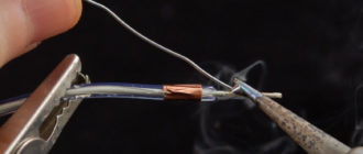
1. Options for connecting wires 2. Connected soldering wires
Another option - welding - is considered professional, since its implementation will require a welding machine. It is worth noting that this method is also considered reliable. If you don’t have a device, you can resort to soldering; for this you will need a soldering iron with all consumables.
The soldering procedure itself is carried out as follows:
- First, the insulating layer is removed from the conductor.
- Then, using sandpaper, the conductor core is cleaned.
- After this, you need to decide what type of core connection will be used.
- The solder should be brought to the tip of the soldering iron, and then the twist should be heated so that the solder flows into it.
- When the soldering has hardened, the area should be washed with alcohol.
- At the final stage, the connection is isolated.
“How to solder wires correctly”
Detailed recommendations regarding soldering wiring are given in the video below (author - Valera shevchenko channel).
Source: https://avtozam.com/elektronika/avtoelektrika-svoimi-rukami/