How to properly connect a two-key light switch and avoid mistakes
Before purchasing and installing a two-key switch, you first need to decide what it is for? And it is designed to control two lighting circuits from one point.
Don't confuse it with pass-through switches, which have different roles. They differ in the number of contacts. Therefore, when choosing, look first of all not at the front panel, but at the back of the switch.
two-key pass-through light switch
two-gang simple switch
Let’s say if you have 2 or more light bulbs in a chandelier, using a two-key switch you can make it so that when you press one key, only half of the lamps turn on, and when you press the second, all the rest turn on at once.
It can also control two different lamps located at separate points from each other - for example, sconces at different ends of the room or in another room altogether.
The two-key switch differs from its single-key counterpart not only in the number of switches, but also, most importantly, in the number of contacts. There are only 3 of them here. One common and two outgoing. Through them, the phase is separated and then returned to the junction box via separate wires or directly goes to the lamps.
Please note that to install a double switch you will need at least a three-wire wire, even if you do not have a PE protective grounding conductor in your apartment wiring.
There is nothing complicated in the connection diagram and in the process of installation, installation and connection of wires to the switch contacts. First of all, the switch needs to be disassembled. To do this, remove the keys themselves. If you can’t do this manually by simply pulling them towards you, use an ordinary screwdriver, prying the keys off from the side.
Next comes the insulating decorative backing; it can either be snap-on or screwed on. Remove this frame.
As a result, what you have in your hands is the body itself with the fastenings on the sides and the internal contact part. The main task is to supply voltage from the phase conductor to the common contact. Further, when two keys are closed, this phase will diverge into one or the other lighting circuit.
To find the central contact, look at the marking, since it may not always be located alone and in the center.
What to do if you don’t understand the inscriptions or they are erased and painted over?
Then you need to use a contact screwdriver with a battery-powered tester with a continuity test function. Insert any metal object (nail, screw) into the supposed common contact. You wrap your fingers around it and touch the other two contacts with a screwdriver.
When you press the keys one by one, that is, turn on one - check, then turn off the first and turn on the second - check, the screwdriver LED should light up each time. If this does not happen, then this is not a common contact.
When you have dealt with the contact part of the switch, take the three-core cable VVGng 3*1.5. It is desirable that the colors of the cable cores correspond to the color markings according to GOST. How to determine by color which conductor should be phase and which should be neutral by reading the article “How to distinguish wires by color.”
To connect the common contact, use the gray conductor phase coming from the junction box. Strip the end of the core, insert it between the contact plates and tighten the screw with a screwdriver.
Next, connect the other two wires in the cable to the outgoing contact connectors.
Connecting the conductors directly to the two-key switch itself is now complete. Insert the housing into the mounting box and tighten the mounting screws.
Then you tighten two spacer screws, which help the mounting fork with teeth to rest as much as possible against the walls of the box and firmly hold the switch body inside it. After this, you can return all the decorative frames and the keys themselves to their place.
The following cables can enter the junction or distribution box:
- power cable from the machine in the panel
- cable going down to the switch
- one (if you have a chandelier with two lighting circuits) or two cables (if the light points are in different places) to the outgoing lamps
To avoid confusion, follow the following order:
First of all, connect all neutral conductors. They are usually blue. Zero does not pass through the two-key switch and goes directly from the panel to the lamp, through the connections in the distribution box.
All stripped wires can be connected using Wago quick-release terminals. Although everyone has a different attitude towards them, they are an ideal option for lighting circuits with minimal loads.
Next in order is protective grounding. This is a yellow-green wire. If you do not have a grounding conductor in your apartment or the lamp body is insulated and the cable is two-core, then this connection will not be in the junction box.
It remains to connect the phase conductors. Here you need to be extremely careful. First, clamp the phase that comes from the power supply into the Vago terminal block. Then insert a wire into the same terminal that comes from the common phase contact of the two-key switch.
You should have 4 free, unconnected wires left. Two of them are the wiring that goes to the chandelier or sconce, and the other two wires are phases connected to the lower outgoing contacts of the two-key switch. Take two more clamps and SEPARATELY connect these conductors through them. Thus, you will connect two lighting circuits to the lamps independently of each other.
In a lamp or chandelier, terminal blocks are usually used for connection. Place the wires of the cable coming from the junction box onto them according to the color marking.
A factory-made lamp must have cores of exactly the color specified in the rules. Phase - a gray or dark-colored conductor should go to the central contact of the lamp, and zero - blue to the light bulb base itself.
The yellow-green ground connection can be attached either to the terminal or directly under the screw on the housing.
Source: https://domikelectrica.ru/kak-pravilno-podklyuchit-dvuxklavishnyj-vyklyuchatel-sveta/
Connection diagram for a two-key pass-through switch
It is known that in spacious rooms or long corridors it is extremely inconvenient to use only one switch installed at the entrance itself. For some time before turning on the device or after turning it off, you will have to do without light. There is only one way to avoid this inconvenience - to install devices of a special design at the entrance to the room, as well as at its exit (they are called pass-through switches or switches).
Design and principle of operation
With the help of such switches, it is possible to control the same light source from two or more points, turning it on in one place and turning it off in another (or vice versa). Thanks to this, while moving, the corridor will be constantly illuminated along the entire path.
The rear view of two-key pass-through switches from different manufacturers is shown in the figure below.
The connection diagram for a double pass-through switch can be implemented using a single-key device, so the question is quite logical: what is the second key for then?
To answer this you will need to understand the following explanations:
- A two-key pass-through switch also contains changeover contacts, but in this case the number of switching groups of lamps increases from one to two .
- The number of conductors connecting two spatially separated switching devices increases to 4.
- With this connection diagram for two-key pass-through switches, it becomes possible to switch two lighting bulbs at once (one to turn on and the other to turn off).
- To see the difference between two-key and single-key switches, a direct comparison will help us. To do this, you will need to remember the connection diagram for the pass-through switch, in which the connection is made on only two wires.
Important! When examining the two schemes together, one can immediately see the difference not only in the number of connectors, but also in the functionality of the devices used.
If in the case of a single key only one group was switched (the lamp was turned on and off), then in a chain with a two-key switch there are already two such groups. According to the diagram of two-key pass-through devices, in this situation it will be possible to turn on the first of 2 light bulbs while simultaneously turning off the second and vice versa.
Lighting control scheme from two places
By connecting double pass-through switches, it is possible to control two light bulbs alternately from two places. This circuit contains a pair of two-key switches, which allows you to turn on one of the lamps at the entrance, while simultaneously turning off the other. When exiting a long corridor, for example, a second device allows the reverse operation. Thus, lighting control is carried out alternately from 2 places.
Important! In this case, the direction of movement along the corridor is not of fundamental importance.
It is possible to implement such a control algorithm only if there is a double pass-through switch. Systems organized in this way significantly simplify lighting control in the conditions described above.
Installation procedure
Before connecting pass-through two-key switches and illuminators, places for their installation are first selected (the first ones should be located at the very exit-entrance to the room). After this, they move on to the main work, carried out in the following sequence:
- First of all, at selected points, installation niches are drilled into the walls with a special crown, the diameter of which is selected to be 72 or 80 mm (depending on the device housing).
- Then special plastic boxes are fixed into them (they are called “socket boxes”).
- When laying the wiring externally, the housings of the switching products are mounted on the wall using self-tapping screws.
- Upon completion of the installation of two-key pass-through switches, proceed to the installation of two groups of illuminators, in each of which the lamps are switched on in parallel (this will eliminate the possibility of a complete blackout of the circuit if one of them burns out).
- Then, two phase wires and one neutral wire are laid from the installed chandeliers or lampshades to the distribution box.
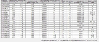
Since the requirements of the PUE require grounding of any connecting wiring with loads, a cable with three cores is laid from the lamps.
Please note: It is recommended to choose the location for installing the distribution box (RC) in the middle of the room, which allows you to save on the length of the wires.
Since the design of the two-key pass-through switch has 6 contact terminals, two 3-core cables will need to be laid from it to the switch. When disconnecting system elements, the wires to the RC must be connected according to the diagram below.
We suggest watching a video on how to connect two-key pass-through switches without a junction box.
Attention! In this installation option, the socket boxes must be deep.
Lighting control scheme from three places
In order to control lighting from three places at once, the previously used scheme with two two-key devices will need to be supplemented with one more (it is called cross). This switch can be placed anywhere in the room between two already installed products.
Structurally, a cross double pass-through switch consists of two two-key devices combined in one housing. In this product, instead of two, one common key is installed on a conventional changeover mechanism, due to which the switching of both lines is carried out synchronously. To understand how to connect a triple two-key switch, it is enough to place jumpers on the terminals of a regular cross switch.
The 3-point connection diagram is organized in such a way that the neutral wire is supplied to both lighting groups at once, and the phase wire is supplied to each of the inputs of the first two-key switch. Regardless of the position of the keys, current will flow only through 2 of the 4 input terminals. From the first pass-through switch, the current flows through the jumpers to the input of the cross switch, and then to the second pass-through switch.
This position of the switch keys determines the path of current through the lighting fixtures. If this group is in working condition (the lights are on), just press the key of any of the switches to remove power from it. The same thing happens when they are turned on: when you change the position of any key, the power circuit is immediately restored.
Four-place lighting control circuit
To organize control of lighting devices from 4 points at once (in two directions) in the room, you will need to install a couple of cross switching products. If there are several lighting groups, preference is given to two-key cross-type switches. When they are connected in series, not only the electrical wiring becomes more complicated, but also the installation of the products themselves according to the algorithm already discussed above.
In this case, jumpers will need to be installed twice (in both pass-through switches, the diagram of which is shown above). When disconnecting such systems, it is recommended to strictly follow the sketch drawn in advance with the designations of the contacts and jumper conductors indicated on it.
Connection diagram for a three-key pass-through switch
When familiarizing yourself with the diagram of a pass-through three-key switch, you need to pay attention to the following points:
- The devices in question have 6 output contacts, which allows you to control three groups of illuminators while being at one access point.
- Before connecting a pass-through switch with three keys, you will first need to mount its loads and disconnect them according to the lighting plan.
- The three-key pass-through switch, the diagram of which is shown in the figure on the right, is not intended for pass-through purposes.
- The main purpose of these devices is to save on wiring costs by controlling multiple illuminators from a fixed point.
In conclusion, we note that the technique of installing a two-key pass-through switch from two places and all its subsequent modifications (from three and four points) resembles the same operations for single-key devices. Its slight complication is justified by a significant expansion of the system’s functionality, supplemented by another illuminator, switched “out of phase” with the first.
Useful videos on the topic
How to make or where to find a two-key cross switch - watch the video below.
Source: https://FishkiElektrika.ru/dvuhklavishnyy-prohodnoy-vyklyuchatel
How to connect a double switch to two light bulbs: diagram, instructions, video
Quite often, when installing electrical lighting networks in domestic and industrial premises, it becomes necessary to control several devices at once from one point.
By connecting a double switch to two light bulbs, it is quite possible to turn this idea into reality.
How to do this, and what safety rules should be followed?
Why do you need to connect a double switch to two light bulbs?
The main reason for using double switches is to optimize the use of electrical equipment that is connected to the same circuit. The most striking example of an optimized circuit is the standard organization of lighting for a separate bathroom. In this case, one key switch is installed on the hallway side. As a result, you can control the lighting in the toilet using one key, and in the bathroom using another.
Thanks to this switch, it becomes possible to perform two actions simultaneously with one movement - turning on the lights in one room and turning off the lights in another.
Connection diagram for a two-button switch with two light bulbs in the presence of a grounding conductor in the network
However, it is necessary to install a general type switch only if they are located nearby. If the rooms are located at a distance, then it is better to use standard separate settings to avoid confusion.
And if you are wondering how to connect a double switch to two light bulbs, then in addition to the connection diagram, you need to study what tools are needed for this, how to prepare for the installation, and how to directly carry it out. Let's take a closer look at each point.
Preparatory stage of work
In the process of preparing for the installation of electrical switching devices, that is, switches, it is necessary to study the structure of the device, its purpose, design and principle of operation. It is also important to prepare all the necessary tools for installing the switch in a domestic or industrial environment.
The number of switched-on lighting devices should be adjusted using a switch, which is equipped with an additional outgoing contact and a separate button for control. In terms of dimensions, it is usually identical to single-key switches, which is provided for greater ease of interchangeability. The main difference is the switching filling.
Devices with two keys have a working part with three contacts, one of which is incoming and two are outgoing. It is the outgoing contacts that have independent control from each other, carried out using a switch.
A wire with a phase must be connected to the terminal of the incoming contact, which comes from the distribution box. Phase wires of consumers must be installed at the terminals of outgoing contacts, that is, from individual lamps of individual luminaires.
The neutral wire, also called the working zero, must be brought out to consumers from the distribution box, and it must not pass through the switch in any way.
For open For hidden
Separately, it is worth noting that two-key switch models have certain varieties:
- models for installation on the wall itself (used for open wiring);
- models for indoor wall installation (suitable for hidden wiring).
Having understood a little about the theory of connection and phases, you need to prepare the workplace and proceed to direct installation.
Step-by-step installation instructions
Theoretically, the process of connecting a switching device can be divided into several main stages. Installation must begin with the cables. So, if the wiring is old enough, then it must be replaced with a new one.
After this, you need to make the correct connection of the wires in the junction box, and then in the switch itself.
To install a lamp or chandelier, you must use the manufacturer's instructions, specially designed for a particular light source.
The first stage - preparing the walls
The wall gating stage is very important and should only be skipped if new wiring with copper conductors of a suitable cross-section is installed. If there are any doubts, it is better to consult a specialist. If the wiring is old, be sure to replace it with a new one.
For lighting purposes, the most ordinary VVGng wire is suitable, the cross-section of which is 1.5 mm² square. If, along with lighting, sockets will be connected, then it is better to give preference to the same wire, but with a cross-section of 2.5 mm².
At the stage of preparing the walls, grooves and arrangement should be carried out, preparation of places where the installation of distribution boxes and socket boxes will be carried out.
At this stage, experts also recommend installing an additional circuit breaker in the electrical panel. This separate device will not be superfluous, especially in situations where repairs are required on the lighting line.
Using such a simple protective device, it will be possible to turn off only one circuit, while the rest will continue to operate in standard mode.
It is worth noting that in the case of wooden houses the type of wiring is significantly different, so a hidden installation method is not used, since this additionally increases the level of fire danger. In this regard, cables must be insulated as much as possible.
Wires are installed from the outside using special insulators. In this case, not internal, but surface-mounted switches are installed, however, the basic principle of connecting the cores to the terminals remains the same.
After the gating of walls of different materials is completed (this can be concrete, brick, or foam concrete), the grooves for laying wires must be sealed using a building mixture or alabaster. Then you can move on to plastering and decorative finishing of the walls. It is recommended to save the location of the wires on the diagram or drawing so that future repairs and replacement of wiring do not cause problems.
Second stage - connection in the junction box
The distribution box is the chamber in which the wiring and connection of the conductors is made. Depending on the type of sockets and switches, the type of connection diagram itself may vary significantly. And first of all, at this stage you should make the right choice of box. If previously metal products were a priority, today plastic analogues are produced that are more convenient and safer to install.
Wire connection diagram: twist the neutral wire from the panel with the zeros of the two connected lamps, and send the phase to the switch.
Direct two output phases from the switch to the lamps - one for each
As already mentioned, there are external and internal types, but during the work it is the external products that are much easier to install.
If it is necessary to disconnect the wires, for example, due to the replacement of an electrical installation, in order to gain access to the built-in distribution box, it will be necessary to dismantle the plaster, and then repair it.
In the case of an external box, its body is always visible. To gain access, simply unscrew the cover and carry out the required actions.
Recently, three-core wires are mainly used in the distribution box, therefore, as in the case of the neutral core, the earth is twisted. If the house still has old wiring, but it is quite reliable and in good working order, then there is no need to replace it. In this case, you should use the connection indicated in the diagram.
In general, there are several options for connecting wires. And the most common today are twisting with insulation in the future, as well as connection using terminal blocks. As for soldering, this method is used quite rarely. If you prefer to use terminal blocks, then you can give preference to a distribution box in which the terminals are already pre-installed.
The third stage - installation of lamps
Depending on a number of factors, the main method of installing a chandelier with two lamps or two separate lamps may vary. Among them are:
- directly the model of the lighting fixture;
- wiring readiness level;
- basics for installation.
The easiest way to replace lighting equipment is when the main core is removed at the installation site, that is, for example, in the center of the room. In the case of new or suspended ceilings (stretch ceiling, plastic or even plasterboard), in order to install the lighting fixture, it will be necessary to install additional fasteners or mortgages.
When two phase wires are supplied to the lamp from a two-key switch, each of them is alternately connected to a specific light bulb. In addition, two neutral cores must be pulled from the distribution box, which are also distributed over two different lamps during the installation process.
If both bulbs are connected to the same wire, they will turn on and off simultaneously, so there is no point in installing a double switch.
By installing two separate lamps in different rooms or rooms, the basic principle of installation does not change, but the pulling of wires directly from the junction box changes. They should be directed in different directions, which is usually done if the rooms are next to each other. As for the distribution box itself, it is better to install it directly above the switch itself, at a distance of about 15-20 cm from the ceiling.
The fourth stage is the installation of the switch itself
The process of installing and connecting a two-key switch usually does not cause any complications. Installation is carried out in a socket box or directly into the wall with fixation with claws or screw connections.
If the lighting equipment has not two, but more lamps, which is not uncommon, then the connection must be made in groups. To do this, the number of lamps is divided into an equal or unequal number of groups, while the wire from contact L1 must be directed to one group, and from contact L2 to the other.
Each master divides into groups depending on his own preferences and the required degree of illumination of the room. When two power modes are required, that is, weak and bright light, then the first core can be run to one bulb, and the second to the rest. To achieve the highest level of lighting brightness, it will be enough to press both switch keys so that all the bulbs light up at the same time.
Useful tips
During the installation of the switch there are several very important points that must be remembered. Moreover, this applies not only to the installation process itself, but also to the selection of the necessary equipment. By following a few simple rules, the system will be more reliable and secure.
Below is a list of recommendations and rules that must be followed for safety reasons:
- all work on connecting equipment in the distribution panel must be carried out by qualified electricians; in the absence of knowledge and skills in this area, interfering with the security system located on the site is unacceptable;
- any actions should be carried out exclusively after a power outage at the general apartment switchboard, and before carrying out any operations with wires, you should make sure that the electrical circuit is de-energized (you can use a probe for this);
- in the case when it is planned to connect and install a contactless device or a device with a dimmer, a detailed study of the circuit is required, since the basic installation principle may differ significantly from the installation of a two-key switch, and may have many nuances.
To summarize, connecting a two-key switch to two light bulbs is quite simple, especially if you have at least some skills in this area. But if you have no experience working with electrical equipment, it is better to leave this matter in the hands of professionals. Remember that working with electrical power can be life-threatening. Improperly installed wiring may cause a short circuit and fire. Don't risk your life and contact specialists!
“Diagram and examples of connecting a two-key switch”
Source: https://pro-instrymenti.ru/elektrika/kak-podklyuchit-dvojnoj-vyklyuchatel-na-dve-lampochki-shema-podklyucheniya/
How to connect a two-gang switch to two light bulbs
Connecting a two-key switch to two light bulbs is quite simple, the main thing is to accurately observe the order of all connections. The two-key switch has terminals for a three-wire wire, while the light bulbs require a regular two-wire cable. When using a standard junction box, it will easily accommodate the necessary connection assembly that will be required for this connection.
Connection diagram
If you have two lamps in different rooms or one chandelier with two bulbs, it will be convenient to use a double switch. Such a switch has three contacts and two jumpers, which are controlled by keys. Another necessary element is a power supply with a two-wire cable, one wire (usually blue) is connected to neutral, and the second (brown or gray) to phase.
A simple and clear schematic representation of the sequence of arrangement of all cores relative to each other can be seen below.
Pay attention to the position of the vertical jumpers on the switch (black square below). These are jumpers that are currently in the off state. As soon as one of the keys is pressed, it will move the jumper to a position in which it is connected simultaneously to both phase and zero, which closes the circuit and supplies current to one of the bulbs.
Similarly, when you turn on the second key of the switch, the jumper will connect to the phase another circuit in which the second light bulb is located, and it will also begin to light.
Naturally, both alternate and simultaneous activation will be available in such a connection. This circuit guarantees complete reliability of the switch and light sources, provided the correct wiring technique is followed, which is discussed in more detail in the next section.
In the meantime, for more advanced users in the field of electrical wiring installation, we attach a diagram compiled by another specialist with professional symbols of all points and connections.
Here you can see an additional socket with a neutral wire included in the circuit. Her example clearly illustrates the method of connecting any other electrical appliance with grounding.
Wiring technology
First of all, let's decide on the wiring that goes separately to each of the connection participants. Let's start with the two-key switch. It has three terminals: one for a common cable and two separate ones. Therefore, to include it in the circuit you will need a three-core cable.
We connect a core with red insulation to the common wire. Below you can see a specially designed stand with a conventional arrangement of the future operating elements of this part of the electrical wiring.
There is a switch on the bottom, a source of electricity on top connected via a two-wire wire with a neutral and a phase, and on the left and right there are two light bulbs. All wires come together in a junction box - a necessary element of installing proper wiring.
The first step is to clean each core of all wires from insulation. First, we remove the white protective material that is common to the internal cores of each cable, and then one by one remove the insulation from all the cores.
Let's take a closer look at the functions of each core of the power cable wires, switches and light bulbs.
The power cable is located on top. On the left there is a brown wire going to the phase, and on the right there is a blue wire connected to zero. Further on the sides you can see the same wires of the light bulbs, in which the blue wire is also the neutral wire, and the brown wire is the phase wire. Here it is worth clarifying that the zero (blue wire) should go to the outer contact of the socket, which is in contact with the thread of the light bulb, and the phase (brown wire) should go to the inner one, which connects to the point in the center of the bottom of the light bulb.
On the switch, as previously mentioned, the red wire in the center goes to the common contact, and the green and gray wires on the sides are connected to the key jumpers.
Now you need to connect the red wire of the switch to the brown phase wire of the power source. We connect the blue neutral wire from the power cable simultaneously to the two blue wires of both light bulbs. And we twist the gray and green wires from the switch with the brown cables going to the phase of the light bulbs. As a result, we get approximately the following picture.
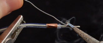
The final step is to tighten all connections securely with pliers and solder them. Then carefully insulate each twist and place it compactly in the junction box.
Source: https://gderemont.com/raznoe/kak-podklyuchit-dvuxklavishnyj-vyklyuchatel-k-dvum-lampochkam.html
Connecting a two-key switch: diagrams, tips, instructions
A two-key switch is a very important element for adjusting the level of lighting in an apartment or private house. The light bulbs can be arranged in groups or one at a time, and the light can be supplied to them by a separate key.
Very often during repairs when carrying out new wiring, the question arises of how to connect a two-key switch to provide several lighting modes. How to connect a two-key switch taking into account the necessary safety measures - read on!
Design and principle of operation of a two-key switch
The design of the two-key switch is quite simple. It consists of:
- Two keys (moving parts up and down).
- Housing (shell), which is removed before starting work with electricity.
- Terminal blocks (those places to which voltage or current is supplied).
Rarely, the third element - terminal blocks - can be replaced in the design with screw terminals. The difference is that the former hold the wire for a long time and securely, and the latter do the same, but not by pinching the wire, but by twisting it, so the first option is easier to connect and lasts longer. The design may also include additional lighting - a dimmer located on each key. Read below about connecting a two-key switch with dimmers.
Inside the two-key switch without backlight there are two wires running parallel to each other and an input for the phase. Each of the terminals suitable for the keys can, independently of the other, open or close the contact, as a result of which one lamp (part of the lamps), the second lamp, or all the lamps together turn on
.
Note! If you need to supply current not to one, but to several light bulbs at once. It is imperative to use stranded wires. This is exactly what the two-key switch model allows you to do.
The principle of operation of the switch is to vary the degree of illumination:
- You can turn on only one key so that one light bulb (or the first group of lights) lights up.
- It is possible to turn on the second key - the lighting will change, since some parts of the room will be clearly visible, while others will be slightly darkened.
- The third option is to turn on “to the fullest” - both keys are in the “on” position - then the room receives maximum illumination.
By the way, some two-key switches consist of two single-key devices isolated from each other. In this case, it is customary to call them modular.
In addition to the external component, such a device can also perform the functions of saving energy and creating a varied atmosphere. Two-button switches also increase safety, since when they are installed in a room, the number of points with electrical voltage is reduced.
Before starting work on preparing to connect the switch, we suggest that you familiarize yourself with the diagram of the two-key switch below:
Preparatory work
When working with electrical equipment, extreme precision and caution must be observed, therefore all materials and tools needed for the work must be prepared and purchased in advance:
- flat and Phillips screwdriver;
- pliers;
- side cutters;
- insulating tape;
- a good construction knife with a sharp blade (for stripping wire ends);
- for crimping it is more convenient to use a special tool - a crimper (it is not necessary if the wires are not stranded);
- switch;
- wires.
Attention! It is very important to turn off the power supply before starting work!
It is extremely important (especially for non-professionals) to correctly draw the connection diagram and lay out the wiring in advance.
The circuit should include the following three wires:
- Ground wire (exited to the light source, indicated on the diagram as “0” or with an arrow pointing down).
- Neutral wire (also led to the light source, designated by the letter “N”).
- Phase is a live wire that, when turned on, should provide power to the light bulbs (the terminals for the phase wire are designated by the Latin letter “L”).
You can install the wiring in one of two possible ways: open or closed. For the first, you will need additional materials - corrugated pipes or grooves, for the second - you need to cut grooves in the walls.
Please note that wiring is done before plastering the walls and ceiling. This means that only after all the wires have been laid and are sufficiently insulated, you can begin finishing work.
To make a small recess under the switch, you will also have to use a chisel and a hammer (this is not necessary if the switch will be installed in the old place).
Connecting a two-gang switch
Before making the connection, you must first strip the ends of the wires by 1-1.5 centimeters to ensure good contact with the terminals. If the wires are powerful, multi-core, at this stage you need to press off their ends.
A switch with two keys should have three wires. One of them is input - phase, and the other two are output, which will supply voltage directly to the lamp itself.
The neutral wire and grounding, as already mentioned, are connected directly to the light source (to the light bulbs, or more precisely to their contacts).
After this, you need to find the phase wire and the entrance to it (unlike the outputs, there is only one). Look at the switch, previously freed from the top casing. At least one arrow must be drawn on it. It usually indicates where the phase will come from and where it will go. Near the base of the arrow, the phase wire should have an entrance.
As a rule, in such switches the terminals for the phase input are marked with the symbol “L”, in turn, the terminals for the output cables are marked with arrow symbols.
To accurately find the phase, use a special device. And if it is not there, you can determine this experimentally by temporarily connecting a chandelier or lamp.
So, you need to alternately connect one wire with pliers in pairs (not simultaneously!) to two others. That is, you select one wire and connect it first to one of the remaining ones, then to the other. This wire, from which first one or another group of lamps (luminaires) will light up, is the phase.
When a phase is found, it can be connected to the input of the switch (this is the first wire that goes to the switch), and the other two wires - to the two output terminals, respectively (these are the second and third wires that go to the switch). Next, all that remains is to insulate the dangerous places on the wires and insert the structure into the socket box, which should be screwed into a place prepared in advance for this.
Afterwards, all that remains is to install the accessories and you can check the device in operation.
To better understand the connection diagram, we suggest watching the video below, which describes in detail and shows examples of the connection diagram of a two-key switch:
Connecting a two-key switch with backlight
The backlit switch makes small additions to the circuit described above. Namely: two more wires appear (so that when the light is turned off, a red indicator on each of the two keys lights up - this makes it easier to find the switch in the dark).
So these extra wires come from the mini LEDs located on the keys. Next, you need to connect one of them to the phase that goes from above, and the second, which comes from below, to the wire that goes to one of the two lamps (groups of lamps).
Useful tips
- Calculate in advance the required (sufficient) cross-section and length of the wires depending on the power of the light sources. The cross-section cannot be less than one and a half square millimeters.
- In addition to the distribution box, it is also recommended to purchase an additional protective device that will protect against short circuits and overloads in the electrical network.
- Choose terminal switches rather than those with screw-in screws, as the first connection option is stronger and more durable: the screws will need to be tightened after a while.
- You can adjust the lighting using a single-key device! But for this, additional equipment is purchased and installed - the so-called dimmer.
- If you install a similar structure to illuminate a bathroom or other damp place, do not mount the switch indoors under any circumstances.
- Note: if the switch is modular, then there is always another one near the input terminal. These two terminals must be connected to each other with a separate wire.
- All connections and connections are strictly prohibited outside special junction boxes. And in the case of complicated environmental conditions, additional protection must be made (for example, from water, humidity, ingress of other solid and liquid substances).
- If you install a switch, for example, for a toilet, then one of the keys can turn on the light in this room, and the other can turn on the hood.
Connecting a switch that controls the light with two keys is not difficult if you strictly follow the instructions given above. Read all the instructions and useful tips first so that you don’t miss anything, then everything will work out!
Source: http://remontnichok.ru/elektrichestvo/podklyuchenie-dvuhklavishnogo-vyklyuchatelya-shemy-sovety-instrukciya
How to connect a double light switch: tips and possible mistakes
› Electrical wiring
13.01.2019
If you install two-key light switches in your home, the average level of living comfort will increase significantly. After all, sometimes it’s too lazy to go to the other end of the room to turn off the light.
But to do this, you will need to familiarize yourself with the variety of connection diagrams and, having correctly distributed the wiring, connect light sources to it.
Pros and cons of connection
First you should optimize your system of electrical devices that will be connected in one circuit. For example, people often install lighting in separate toilets and bathrooms by running the wiring to a two-button switch. This makes it possible to control the light in different rooms with one switch. It is especially convenient to turn off the lights in both rooms at once.
Also, a double switch can be used in a chandelier with two bulbs, which will allow you to adjust the light intensity. When you turn on both keys, the light will be as bright as possible, and when you turn on one, it will be dim.
Remember that installing a joint switch for two or more rooms is reasonable if the rooms have adjacent walls. If rooms are located far from each other, use separate switches.
As you already understand, installing such an electrical system will greatly simplify the management of energy consumption and lighting brightness. Moreover, installing an adjacent light control unit will save money on the required materials and installation work.
How to decide on a connection diagram for several light bulbs
There is a difference when connecting devices to a 1-key and 2-key switch. For a clearer understanding, let's look at the connection diagrams separately.
Connect several light bulbs
1. The phase should be led from the meter to the switch, and from the switch to the light bulb;
2. Zero goes directly to the light bulb, bypassing the switch.
This principle is the most common and does not require any additional costs if you need to connect, for example, a chandelier. If you use several light bulbs at once, then with this connection they will light up and go out simultaneously.
Option with wiring connected to a two-key switch
1. The zero goes directly to the light sources, connected in parallel between them;
2. The phase wire goes to the switch, in which each key will supply electricity to separate power plants.
Thus, you can use either two or one light source at once by turning on one or two keys, respectively.
The advantage of this connection is that in the case of different rooms, it is possible to control the light from one switch. And if there is light in one, it’s easy to change the brightness of the light.
In modern houses, when installing electrical wiring, a three-core wire is used. The overall connection picture does not change; only an element is added that “grounds” the wiring. It connects to the metal parts of the lamps, bypassing the switches.
If there is a socket in the node with the switch, then the connection is made differently. The ground wire must be run from the junction box to the outlet due to the higher potential load on the outlet than on the light bulb.
Step-by-step installation instructions
Let's conditionally divide the work into several stages: - if there is old wiring, it is necessary to replace it according to standards corresponding to the energy consumption of the installed devices; - installation and connection of wiring in the distribution unit;
— connection of the switch and power devices.
Step No. 1 - preparing the walls
If you have already installed new wiring with a copper cross-section of the appropriate diameter, you can skip the wall groove stage. If you are not sure about the quality of the wiring, consult a specialist.
For reference: for lighting groups of devices, copper wire with a cross-section of 1.5 mm2 is used. If you are going to connect a socket into the circuit, the socket wiring standard of 2.5 mm2 is used.
At the wall ditching stage, it is necessary to install all additional elements. For example, additional circuit breakers in the electrical panel. This step is due to the fact that in the event of a breakdown, only one power circuit will be de-energized, which will allow the remaining devices to operate normally.
To prepare smooth round recesses in the walls, a groove is used (due to an additional special vacuum cleaner), but at home they use hammer drills and circular saws, and some even do it manually.
If you have a wooden house, do not use hidden wiring. In your case, the likelihood of a fire will be increased, which will require additional insulation of electrical cables.
Route the wires along the outside of the walls using insulators. Use overhead switches instead of internal ones - the connection stage is exactly the same, which will provide you with increased fire safety.
After finishing the walls (concrete, aerated concrete or brick), proceed to laying wires and covering the areas with special mixtures, such as alabaster. Then comes plastering or other wall finishing. Don’t forget to save electrical wiring locations on the drawings - you will need them during the next repair.
Step No. 2 - distribution box
The distribution box is a space where different wires are connected and wires are routed to power units. First, you should decide on the required type of box for your case. Previously, metal structures were used, but now safer and more practical plastic analogues have been invented. The connection diagram of the switches will not change depending on the type of box.
Two types of boxes are used in installation - external and internal. At home, it is recommended to use external types of boxes. They have an advantage if repairs are needed. If you need to replace electrical wiring or disconnect circuit components from the overall circuit, you will have an order of magnitude fewer problems.
The junction box housing will always be visible - you just need to open the cover and carry out the necessary work.
Due to their popularity, three-core wires are increasingly being used in home wiring. The ground wire twist is also located in the box. And if the wiring is outdated, but its cross-section is sufficient, there is no point in replacing it - use the existing wiring with a more convenient layout.
To properly insulate the wires from each other, several options are used. For example, terminal blocks - in this case, you can purchase a box ready for installation. Soldering is rarely used, and it is not beneficial under high loads (it may melt). The most common option is twisting - cheap and cheerful.
Step No. 3 - preparation for installation and connection to the power grid
Installation of individual lamps or chandeliers with individual light sources is carried out differently, depending on the following points: - the presence of wiring; - the type of base for mounting the lamp;
- type of lighting fixture.
It will be easiest to cope with the installation when the wire is already connected to the terminal at the installation site of the lamp.
Additional fastenings may be needed when installing on suspended or plasterboard ceilings, depending on the weight of the entire structure.
If you connect the lamps to one wire, then turning on will occur from one button. And if you already run 2 phase wires for each switch, then separately.
Installation of lamps with one switch for different rooms is carried out according to the same principle as with two, but with one difference - the wire from the junction box will go to another room. It is recommended to install the box at a distance of 20-30 cm from the ceiling.
Step No. 4 - installation of the switch
There is no difficulty in installing a two-key switch. Installation in the place of a socket box or in a prepared special hole occurs using special fixing terminals.
Often there is more than one lamp in ceiling lighting. In such cases, the connection is divided into groups of lamps, to which wires are drawn from different contacts (L1 and L2).
The number of lamps in a group depends on the desired light saturation. There are two modes - intense and dim. Here you yourself need to decide how many lamps will turn on when you press each key, and in what sequence.
Practical recommendations and advice
If you adhere to a set of simple rules, then this kind of installation work will not be dangerous, which is especially important for closed type networks.
Remember that any work with electricity should be carried out only after the apartment or house has been completely de-energized at the main panel.
Before any wiring problem, make sure that there is no voltage on the phase. When dismantling a two-key switch and installing a dimmer or non-contact type switch, study the connection diagram in detail - they differ in each case.
Installing electrical switches and wiring in premises does not always require the involvement of a qualified specialist, however, it is always worth remembering the rules of safe work with electricity, taking into account key factors, and based on this, you can choose the right connection diagram specifically for your types of lamps.
How to connect a double light switch: tips and possible mistakes Link to main publication
Source: https://vilki-rozetki.ru/elektroprovodka/kak-podklyuchit-vyklyuchatel-dvojnoj
Connection diagram for a two-button switch for two light bulbs
In some cases, instead of two or three conventional switches, it is advisable to install one group switch (two- or three-key). We propose to consider in what situations it is justified to use such devices and their design features. At the end of the article, we will describe in detail how to connect.
Purpose and scope of application
This type of device allows you to switch two or three (if a three-key design is used) groups of devices (lighting sources, hood, etc.) or turn on/off individual groups.
Using a two-key design, it is easy to control the intensity of room lighting. For example, if you are using a three-bulb light source, you can connect it to create two groups. Then you can turn on one, two or all light bulbs at once. How to implement this option will be described below.
This is what double and triple switches look like
The second, no less common option is to control the lighting of a separate bathroom.
Of course, you can use two single structures for these purposes, but installing a double one provides the following advantages:
- when installing hidden structures, you will only need to make one seat;
- the cost of a one-key and two-key switch is approximately the same, but two of the former are needed;
- two devices look less aesthetically pleasing than one and take up more space, which can be critical in some situations.
Design Features
Two-key devices for turning on/off the load are structurally almost identical to single-key devices, the main difference lies in the switching mechanism. Below, Figure 2 shows the main design elements.
Figure 2. Main design elements
Designations in the photo:
- A – keys;
- B – external panel-casing;
- C – internal panel;
- D – switching mechanism;
- 1 – input;
- 2 and 3 – contacts for control wires going to the chandelier.
Now let's look at how the contact group diagram of the switching mechanism is arranged; it is shown in Figure 3.
Drawing. 3. Contact diagram of a two-key device
As can be seen from the presented diagram, the switching mechanism has three contacts, “1” is a common input, “2” and “3” are two control outputs.
Now that we have figured out the design of two-key switches, we can move on to their connection diagram.
How to connect two-key switches
Let's consider the connection using the example of a two-section lighting fixture (the diagram is shown in Figure 4). Note that this is a standard option that is used to turn on/off any devices.
Drawing. 4. Connecting a two-section chandelier to a double switch
As can be seen from the figure, the zero is supplied directly to the lighting sources, in contrast to the phase, which is switched. When the “cl1” contact is triggered, “L1” is turned on, respectively, “cl2” is responsible for the operation of “L2” and “L3”. As a result, we can set three options for the intensity of lighting in the room (one, two or all light bulbs are on).
Please note that the phase is supplied to input “1”, and two control lines are supplied to the outputs (“2” to “L1” and “3” to the group “L2” and “L3”). The supply can be made with a three-wire cable; if this is not available, then 3 wires are laid.
The option shown in Figure 4 is more general. Therefore, I will also give a simpler connection diagram specifically for 2 light bulbs (lamp):
Simple connection diagram
Why is it necessary to switch the phase?
The above circuit will function even if the polarity is reversed, but despite this, it is the phase wire that must be connected to the contact group (input “1”). This condition, set by the Electrical Installation Rules, is directly related to safety. If you switch zero, the voltage will always remain on the contacts, which can lead to serious consequences during maintenance or repair.
Step-by-step instructions for installing a two-button switch for the hood and lighting in the bathroom
Let's say we need to install a two-key switch for the hood and lighting in the bathroom. We will assume that all the wires have already been laid and connected, and the hood and lamp have been installed. Our task is to make switches in the box and connect the equipment to the switch.
Let's describe how to do this work with a minimum amount of tools; everything we need is shown in Figure 5.
Tools for work
List of tools:
- Screwdrivers with Phillips and slotted tips.
- A special knife for removing insulation (you can take a regular one);
- Four WAGO double terminals. They will be needed to make the connections. Of course, this can be done in other ways (soldering, welding, twisting), but we settled on this option because it is the simplest and does not require special tools or skills to work with them. You will find detailed information about WAGO terminals on our website.
- Level.
- Probe (needed if wiring is made with monochrome wires).
The algorithm of actions will be as follows:
- We de-energize the wiring in the switchboard - this is a prerequisite for carrying out the work.
- We carry out the switching in the box, connect the zero to the common wire from the lamp and the hood, connect the phase to the switch, connect the outputs from it to the control wires from the devices. In order not to be mistaken with the purpose of the wires, Figure 6 shows the standard color layout.
Wire colors according to purpose
If the wires are longer, cut off the excess. Using a knife, remove the insulation from them (approximately 10-15 mm from the edge) and connect them in WAGO terminals,
- We make the connection to the switch terminals, to do this we cut off the excess and strip the insulation. Now you need to connect a phase to the common input of the switching mechanism; if three wires of the same color are connected to the connection point, you will need to find it. To do this, apply voltage to the wiring and touch the wires one by one with the probe. When what you are looking for is found, the neon light in the device will light up. After this, turn off the voltage and continue working.
We connect the control wires from the hood and the lamp to the outputs of the switching mechanism; the order of connection does not matter.
- We install it in a glass (if the device is a hidden type) or in a prepared place (external version), after which we level the external panel.
- We connect the hood and lamp. They usually come with a terminal block, if not, you can use WAGO double terminals.
- At the final stage, we check the operation of the assembled circuit. If you adhere to this algorithm of actions, then there will be no problems.
Note that connecting a three-key switch is done in a similar way, only 4 wires are required to connect it.
Source: https://www.asutpp.ru/shema-podklyucheniya-dvuhklavishnogo-vyklyuchatelya-na-dve-lampochki.html
How to connect a double (two-button) switch
Light switches are one of the most common electrical installation products. Every apartment, house, office has at least a few of them. To save space and reduce the amount of work, switches can have not one key, but two or even three.
But double ones are still more popular. That’s why we’ll talk further about dual (with two buttons) switches. They are also called two-key, two-button, double, etc. Connecting a double switch is quite possible for a novice electrician.
Even without special skills, you can handle this yourself.
Switch device with two keys
If you need to connect two light bulbs or two groups of lamps, and it is necessary for them to turn on independently of each other, you need a two-key switch. They are very easy to distinguish - two buttons are installed in one housing. By the way, the presence or absence of backlight does not affect the connection in any way. Neither the schemes nor the principles change.
How does a double light switch work?
The circuit of a two-key switch is simple: these are two normally open contacts, each of which is controlled by its own button. This means that in the initial state no current flows through the switch, since the contacts are open. By pressing the key, we close the contacts, the lights light up. This is the operating principle of any switch. The two-key one differs only in that it has two groups of contacts.
If you look at the design of a two-button switch, we see that it has one input and two outputs. The phase is connected to the input of the switch, and the wires that go to the light bulbs/chandelier are connected to the output.
Safety precautions - be careful
Connecting a double switch yourself is not difficult. You can cope even without special knowledge and skills. But you have to be extremely careful - it's still electricity. We must follow safety precautions. Things to remember:
- Do not handle exposed wires with both hands.
- Use special tools from an electrician's kit with insulated handles.
- Before work, check which wire the phase is supplied to, and mark it if necessary. If all the wires are the same color, there should be a bright mark on the phase wire. This could be a piece of electrical tape or other sticky material, preferably in a bright color. You can use nail polish, paint, etc. It is only important that the mark is visible from all sides. Checking with a phase indicator
- Make sure there is no voltage on all other conductors.
The easiest way to check is to use an indicator screwdriver. If you touch a live wire with it, the signal light on it will light up. This is how the phase is determined. If the light does not light, it is the neutral or the wires coming from the light bulbs/chandelier. Only after understanding all the wires can you begin to connect the two-key switch.
Connection diagrams for a two-key switch
When connecting the switch, remember that the phase that comes from the panel is supplied to its input. This is the basic rule. This is the only way the connection will be correct. The phase is taken in the distribution box, which is usually located above the switch (sometimes, with lower wiring, below it) in the distribution box.
Connecting a double switch is done according to this scheme
Please note that work is carried out with the voltage turned off. If there is a circuit breaker through which the lighting is powered, turn it off. If the wiring is old, unscrew the plugs. Before work, make sure that there is no voltage on the wires (touch all with an indicator screwdriver).
To two light bulbs
Most often, two loads are connected to a two-key switch - one light bulb or a group of lamps. In any case, the scheme will be the same.
A phase wire is connected to the input of the switch. The contact at the top of the switch is loosened (turn the bolt a couple of turns counterclockwise), the wire stripped of insulation is inserted along the plate (stripping 4-6 mm), the mounting screw is tightened. When tightening the bolt, apply considerable force. You can check whether the wire is securely fastened by tugging it well a couple of times. If you can’t get it, everything is fine.
Schematic diagram of connecting a switch with 2 keys
In the same way, connect two wires that were sewn from light bulbs/chandeliers. The contacts to which you need to connect are located below. The principle is the same - loosen the screw, insert the wire, tighten it, pull it.
It doesn’t matter where to connect which wire (to the right or left contact). It just depends on which key will turn on which light bulb. If desired, they can be swapped later.
After the connection is completed, install the keys, turn on the power, and check the operation of the switch. If everything is done correctly, there should be no problems.
Connection diagram for double switch with socket
In addition to just switches with two keys, there are blocks with a socket. In this case, the connection of the double switch does not change, but a zero and grounding must be added to the socket.
Connection diagram for double switch with socket
So, we supply a phase to the block of switches, and from the output of the switches the phase goes to the light bulbs. We supply a phase to the socket block (you can take it from the entrance to the switch block), set “zero” to the second contact - from the corresponding bus on the panel. We connect the ground to a special ground contact.
What to do if there are more wires
In the double switch connection diagram described above, three wires are needed - a phase from the distribution cabinet and two wires from the light bulbs. But sometimes four or more come. What to do then?
- Find the phase and mark it. It is advisable to bend it so as not to touch it in the future.
- Find two wires that go to the light bulbs. This can be done using a multimeter in dial mode.
- The remaining wire is most likely ground. According to the new standard, it is required even when connecting light bulbs. If you have a ground wire on your chandelier/light bulbs and it is connected to the switch, then we simply twist both wires. If the light bulbs or chandelier do not have an “earth” wire, simply insulate the wire and leave it. There is no need to cut it off - maybe later buy a chandelier with an “earth” wire.
There is a weak point in the specified algorithm - we assumed that the remaining wire is ground. Logically, this is correct. But, unfortunately, there are exceptions. Therefore, before manipulation, you should decide whether this is really “earth” in front of you.
To do this, you can measure the voltage using a multimeter (set the measurement limit to 1000 V - just in case, then you can reduce it). We touch the phase one with one probe, and the nameless one with the second. If it shows 220 V or a figure close to it, this means “zero” and not “ground”.
If the readings are lower than 220 V, this is “ground”.
This “measuring device” can determine the “zero” or “ground” of your unknown wire
If you don’t have a multimeter, you can use a light bulb to which you connect two wires (you can take a table lamp and wrap two wires around the plug). Take single-core wires, rigid, of sufficient diameter. Their ends need to be cleaned, but you will only hold on to the insulation. We touch the phase wire with one end, and the “unknown” wire with the other. If it’s on, it’s “zero”; if it’s off and the machine is knocked out, it’s “zero.” This method is dangerous to health, so we act very carefully.
If the connection is incorrect
If you decide to replace the old switch with a new one, and not a phase, but a zero is connected to the old one, this is wrong and you need to fix everything urgently. The light bulbs will work, but with this connection they are always energized. In this case, even replacing a burnt-out lamp is a deadly undertaking. I'm not kidding. This is true. Therefore, if the switch is connected incorrectly (if zero comes to it), everything must be corrected. There are two options here:
- The phase and neutral on the distribution box are reversed. In this case, all switches connected to this branch are connected to zero. You need to verify this by carrying out a simple test - using an indicator screwdriver, touch the wire that goes to the input of the switch (a single wire that goes to the connector located at the top). If the indicator on all switches does not light up (be sure to check its functionality), the zero and phase in the distribution cabinet are definitely reversed. Then we turn off the input machine and switch the ends. If this doesn’t tell you anything, and you have no idea what to do, it’s better to call an electrician. If the switch is set to “zero”, you need to redo it
- Phase and neutral are reversed in the distribution box. In this case, the incorrect connection is present on only one switch. In this case, we change the zero and phase in the distribution box (do not forget to turn off the machine before doing this and make sure that there is no voltage on the phase wire).
If you are connecting a double switch with your own hands for the first time, it is better to double-check your actions several times and work very carefully.
Switch installation
Finally, let's talk about how to install switches. It doesn’t matter how many keys they are. The sequence of work is the same:
- From the distribution box, the groove is lowered vertically down (or up with lower wiring).
- At the selected height, a hole is made in the wall for the socket box. Typically, a drill attachment is used - a crown.
- A socket box is installed in the hole. The voids between the socket box and the wall are filled with a solution, preferably with good adhesion to concrete and plastic.
- A small diameter corrugated hose is laid from the distribution box to the entrance to the socket box. Wires are then passed into it. With this installation method, it is always possible to replace damaged wiring.
- The switch is disassembled (the keys and decorative frame are removed) and the wires are connected.
- Installed in the socket box, secured with spacer tabs, tightening the fixing bolts.
- Install the frame, then the keys.
This completes the installation and connection of the double switch. You can check your work.
Source: https://elektroznatok.ru/provodka/podklyuchenie-dvuhklavishnogo-vyklyuchatelya
Double switch - types, device, selection features and switch connection options
Currently, the number of electrical goods on the market is presented in a wide range. Everyone can find something that suits them better than the other: sockets, light bulbs, wires and, of course, switches.
Switches are now available in many variations - touch-sensitive, keyboard and many others. However, the most common are keyboards or push-buttons. Among them, double ones stand out. They usually connect to two light bulbs at once. It is compact and easy to use.
In online stores you can find out approximate prices and see photos of double switches. We will talk about them now.
How do two-button switches work?
When installing a large number of lighting fixtures, in most cases it is necessary to turn them on separately. It is for this purpose that a double light switch comes in handy. If there are two light bulbs, then connect them separately to each key. If there is a large number, they are divided into groups.
When connected to this type of switches, the lights will turn on independently of each other. For example, you can turn on one light bulb or group, or you can turn on all of them at once.
The design of the double switch is simple, like an ordinary one. There is a contact that is normally disconnected. As soon as the button is pressed, the contact closes and the signal to turn it on or off is transmitted through the wire.
Unlike other types of switches, double ones have a pair of contacts connected separately to each key. They are not connected to each other in any way and act like two single switches, only in one frame.
When connecting this option, even a novice electrician should not have any problems. The switch has one input connector where the phase is connected. On the other side there are two output connectors; wires of electrical appliances are connected to them.
The connection diagram for a double pass-through switch is slightly different from the usual one. This is because the pass-through switch is simply two separate single switches. It requires two phases.
Safety when connecting a double switch
Despite the fact that connecting a switch is not a difficult task, safety comes first. Electricity is dangerous, so you must carefully follow all safety rules when working with wires.
First, never touch exposed wires with your hands. To protect yourself, use only special tools. All tools in an electrician's kit are equipped with insulating handles.
Before you start work, decide which wire is the phase wire. For this, a special screwdriver with an indicator is used. When you touch it to a live wire, the light bulb in it lights up.
Once the phase is determined, mark it with something bright. If all the wires are insulated with different colors, just write down on a piece of paper which one is phase. If the color is the same everywhere, you can mark it with bright electrical tape or nail polish.
Next, use the same screwdriver with an indicator to check the remaining wires for absence of electricity. Next, the connection diagram for a double switch will be described.
Connecting a double switch
Once you have marked the wires and determined the phase, you need to turn off the voltage. If the system is new with a switch, just flip the switch. If you are working with an old system, you will have to unscrew the plugs. Once this is done, check the wires for no voltage using the indicator.
If everything is checked, you can start working. Let's look at how to connect a double switch to two light bulbs. A phase will be connected to the input, as mentioned earlier. Only in this case will the connection be correct and the current will flow to the lighting devices.
In order to connect a phase, the wire must be freed from insulation by approximately 5 mm. Next, in the switch at the top of the plate, slightly unscrew the screw.
A wire is placed under the plate and the bolt is again tightened to the limit. If installed correctly, the wire cannot be pulled out.
The wires coming from the light bulbs are connected using the same system, but at the bottom of the switch. There will be two plates for two wires respectively. The connection will be identical to the phase. The bolt is also unscrewed, the wires are inserted and tightened. Check to see if the bolts are tightly tightened.
In this case, the wires from the light bulbs are connected in any order. Once everything is completed, the keys are inserted into the frame, securing them. After this, you should connect the electricity and check the operation.
If everything works correctly, install the switch in place. The work is completed. The same principle is used to connect a chandelier to a double switch.
Photo of double switches
We also recommend viewing:
Source: https://stroimaterials.ru/dvojnoj-vyklyuchatel/