Reinforcement products: types, methods of their manufacture, areas of use
Reinforcing products are semi-finished and finished structures from reinforcing elements used for the production of prefabricated and monolithic reinforced concrete elements. The greater the degree of readiness of the reinforcement products, the less labor costs can be done directly on the construction site.
The following types of fittings and reinforcing products are distinguished:
- reinforcing mesh - welded and knitted;
- frames - flat and spatial;
- clamps;
- mounting loops;
- ropes and bundles of prestressing reinforcement with and without anchors;
- embedded elements.
Welded reinforcement mesh
The most popular products are reinforcing mesh, made from cross-shaped welded wires or rods.
To produce these metal products, reinforcing wire or rods with a diameter of more than 3 mm are used. Meshes with a diameter of longitudinal rods of less than 5 mm and transverse rods of less than 10 mm are produced in roll and flat forms; more than these values - only in flat forms. The mesh cells are made square or rectangular.
Depending on the diameter of the wire and rods, meshes are conventionally divided into light and heavy. Lightweight ones include meshes with element diameters up to 10 mm. If rods over 12 mm were used in at least one direction, then such meshes belong to the heavy category.
Wires or rods of only the same diameter are placed in one direction.
Based on the location of the working reinforcement, meshes are divided into two types:
- the working fittings are located only in one direction, in the perpendicular direction - distribution fittings are mounted;
- working fittings are used for both directions.
The intersections of the reinforcing elements are connected using spot welding.
Welded mesh is used for reinforcing reinforced concrete elements, brickwork, when laying foundations, for screeding cement floors, and for reinforcing road surfaces. Welded reinforcing mesh is used in vegetable growing and floriculture in the construction of greenhouse frames, as well as for creating fences for decorative and functional purposes. In fur farming, mesh is used to make cages.
Light meshes are produced with a width of 0.65-3.8 m, heavy ones - 0.65-3.05 m, mesh length - up to 9 meters.
Knitted reinforcement mesh
Manual knitting of reinforcing mesh is used for small volumes of construction work. For this purpose, soft wire after annealing with a diameter of 0.8-1.0 mm is used. The tool used for tying is reinforcement wire cutters with slightly blunt teeth to prevent the wire from being bitten off.
The method of manually knitting reinforcing mesh is used:
- in cases where it is not possible to connect reinforcing bars by welding, for example, in some truss units, in the production of non-standard building structures;
- for consolidation of reinforcement products directly on construction sites;
- for small volumes of reinforcement, when the use of welding equipment is impractical;
- for carrying out urgent work when it is impossible to deliver finished reinforcement products within the specified time frame;
- when used for reinforcing waste wire or non-weldable steel rods.
To increase the productivity of the mesh binding process, instead of wire, special paper clips are used - clamps made on automatic equipment.
Reinforcement frames
Reinforcing frames can be flat or three-dimensional.
In welded flat frames, the transverse rods are located in the same plane. Depending on the number of longitudinal rods, frames are divided into two-, three- or four-branch.
These frames are the starting material for creating spatial reinforcement frames intended for reinforcing tensile or flexural reinforced concrete elements with a small cross-sectional width.
The rods are connected by contact welding, carried out on high-performance multi-electrode welding machines. In the absence of such equipment, electric arc welding or manual knitting method is used.
In spatial reinforcement frames, transverse rods are located in different planes. These products are made by assembling individual rods, reinforcing mesh, flat frames, clamps, embedded elements, and mounting loops. All parts are connected by welding - contact spot or electric arc, it is possible to use knitting.
To add additional rigidity, round reinforcing bars are replaced with profiled products, for example, angles, as well as square bars or steel strip.
Advantages of using ready-made frames:
- the possibility of using highly efficient welding processes in specialized production workshops;
- complete absence of reinforcing steel waste, which is ensured by rational cutting;
- acceleration of construction work by 30%;
- no need for specially trained workers to be present at the construction site.
Prestressed reinforcement products
Enlarged reinforcement products - meshes and flat and spatial frames - reinforce non-tensioned structures. For prestressed elements, ropes (Fig. 1) and reinforcement bundles (Fig. 2) are used. Tensioning of reinforcement products is carried out in three ways: on stops, on concrete, and electromechanically.
- Stop tension is used in the production of precast concrete elements. Before concreting, the reinforcing products are pulled onto special stops or forms to a given value. Fixed with clamps. After the concrete mixture has hardened and the concrete has reached the capacity specified by the project, the reinforcement is released from the clamps.
- To implement the second method, channel formers are installed in the formwork, which use pipes, rods, rubber hoses with a metal core. The diameter of the channel formers is 10-15 mm greater than the diameter of the reinforcement product. They are removed from the concrete 2-3 hours after finishing concreting the structure. After the concrete reaches its design strength, reinforcement products are inserted into the holes, which are then tensioned.
- The electromechanical tensioning method involves passing an alternating current of a certain frequency through the reinforcement. As a result of the effect of thermal expansion, the reinforcement lengthens, is fixed, and when cooled, it shortens again and transfers compressive forces to the concrete.
Prestressed reinforced concrete elements have high resistance to dynamic loads and durability.
Other reinforcement products
- Clamps are used to create spatial frames. These parts take on part of the effort during operation of the structure. Clamps are made individually or from reinforcing mesh. They can have the shape of closed or open quadrangles on one side, covering the working reinforcement from the outside. Clamps are made on bending equipment from rod or coil reinforcing steel.
- Mounting loops, which are installed for convenient slinging of reinforced concrete products, are produced in reinforcement shops on bending machines from reinforcing steel with increased ductility.
- Embedded parts are used to connect prefabricated reinforced concrete products. They are made from sheet, strip, sometimes shaped - corner - rolled products. Normal or tangential anchors are welded to them using a T-joint or lap seam, which are used to fasten the reinforcement product in concrete. Embedded parts can be made with holes, equipped with stops to allow shear work, and short pieces to fix the position of the part or working reinforcement. The size of the embedded plates and the diameter of the anchors are determined by the type of joined elements and the loads they perceive. When producing plates of significant size, which are located on top during molding, holes are made in them for air outlet and the ability to control the quality of concrete.
Reinforcing products are produced in special workshops equipped with cutting, bending and welding equipment.
The most effective is the organization of a complete technological flow - from the preparation of reinforcement parts to the receipt of finished construction reinforcement products.
Source: https://www.navigator-beton.ru/articles/armaturnye-izdeliya-vidy-sposoby-ih-izgotovleniya-sfery-ispolzovaniya.html
Types of cable fittings. Types and types of cable fittings
Cable fittings are a popular product for performing a variety of electrical work. High-quality and durable fittings guarantee the safe operation of electrical networks and perform important functions in ensuring the reliability of cable and overhead power lines.
Cable accessories (CA) are a variety of electrical products designed for fastening and mechanical protection of cable and overhead lines.
The most famous types of spacecraft include:
- Electric couplings for various purposes;
- connectors for installation of electrical conductor products;
- sleeves for insulating and protecting joints;
- KA for connecting self-supporting insulated SIP wires;
- plugs for conductor lines;
- materials used for self-sealing couplings;
- equipment for cutting electrical cables.
There are three main categories of wire fittings:
- Station - a special set of necessary devices and tools that ensure the functioning of energy facilities;
- optical fiber communication lines. These spacecraft are intended for laying, connecting, and then fixing them.
- Internet cable system is used for internal connection of Internet cables in buildings.
Couplings for overhead lines
The main element of cable fittings is the coupling. A variety of types of couplings are used:
- Branch;
- end;
- transitional;
- connecting.
Couplings used in power transmission lines:
-
RayGel-23-M coupling with gel filling, maximum voltage 0.6/1 kV.
-
Repair coupling REPJ-42/1, maximum voltage, 35 kW.
-
End coupling 3KVTP-10, maximum voltage, 10 kV.
-
Adapter couplings TRAJ-01/4xxxx-3SB, maximum voltage, 0.6/1 kV.
-
Branch coupling EPKB-24B/1XU-2XU, maximum voltage, 12/20 kV.
-
Adapter coupling TRAJ-12/3, maximum voltage, 6/10 kV.
Couplings are used to organize the work of electrical networks for various purposes. They contain a set of components and materials to create high-quality branching or connection of cables and wires.
In addition to strong connection of wires, couplings provide enhanced insulation and sealing of connection areas. The configuration of a certain type of coupling is influenced by the characteristics of the connected lines.
SIP connection
When installing overhead power lines with SIP, it is often necessary to install individual conductors of current conductors. For such purposes, mounting sleeves are used. For example, in cases where, when placing SIP on supports, the conductor ends and it is necessary to extend the marking and installation with similar sections of conductors. For installation of wires, special designs of fittings for self-supporting insulated wires are used in the form of connecting sleeves for bare wires with sealing of the connection with heat-shrinkable tubes.
Insulated, sealed, branch clamps
This type of fittings is used to connect a SIP line to a main non-insulated line made of copper and aluminum with voltage up to 1 kV. When the bolted connection of the contact plate legs is tightened, a strong electrical contact is formed, piercing the insulating coating of the outgoing conductor, and at the same time firmly clamping the uninsulated main wire.
Pressable branch clamps:
- OA-120T-2
- OA-10-1
- ZOAP-500T-1
- OA-16-1
- AOA-3/2T
- OA-150T-2
- OA-150-1
- OA-120-1
There are ZORZB type clamps for working with SIP neutral wires with an insulated neutral and for making phase branches of wires under operating conditions in low humid environments and where moisture penetration into the clamp is prevented.
ZORZB are designed for a different number of lead-out conductors, which is marked with a number. “C” means the type of head of the branch bolt - shear, sometimes not yet shear. The digital designation placed before and after “/” indicates the range of cross-sectional areas of the main and branch wires.
Insulated sleeves
This fitting is used for aluminum stranded conductors. The internal volume of the structure is filled with contact lubricant to protect the metal from oxidative destruction processes that reduce contact. This design reduces energy losses. The insulating material used is a high-molecular polymer that is resistant to sunlight and various atmospheric conditions.
Types of connecting press sleeve:
- SSIP-150-3(A);
- SSIP-35-3(A);
- SSIP-50-3(A);
- SSIP-120-3(A).
GIN sleeves are produced for mechanical and electrical connections of SIP neutral wires.
The main purpose of SIP fittings is to perform high-quality transmission of electrical energy via overhead power lines; in addition, they are used in lighting networks regardless of voltage. The production of devices is made from materials that are most resistant to the negative influences of the environment. Cable fittings are high-quality electrical products that can operate for several decades without breakdowns.
Source: https://sts-kabel.ru/news/vidy_kabelnoy_armatury/
Purpose of fittings
According to their purpose, steel reinforcement is divided into working, distribution, mounting and clamps.
Working fittings
Working reinforcement or longitudinal reinforcement - reinforcement is designed to absorb mainly tensile forces from the own weight of structures and external loads, and in some cases, also compressive forces.
Distribution fittings
Distribution reinforcement is designed to evenly distribute loads between the working reinforcement rods and to ensure their joint operation. Connecting the distribution fittings to the working ones by welding or knitting using a binding wire ensures their joint operation.
Transverse working rods in welded reinforcement frames of beams protect concrete from the appearance of oblique cracks near the supports and facilitate the assembly of frames. In columns, clamps prevent buckling of vertical reinforcement bars. Distribution reinforcement connects the working rods to each other, preventing the working reinforcement from moving during concreting.
In welded mesh used for reinforcing slabs, wall panels, decking, etc., working and distribution reinforcement are usually located perpendicular to each other, forming cells. At the intersection points, the steel rods are welded.
For working reinforcement of welded mesh, ordinary reinforcing wire or hot-rolled reinforcing steel is used (A500C reinforcement, less often B500C); The distribution reinforcement of welded mesh is made from ordinary reinforcing wire (VR-1).
Mounting fittings
The mounting fittings do not take any effort and serve to assemble the frames and hold all installed fittings in the design position. When concreting, the mounting reinforcement is sometimes removed.
CLAMPS
Clamps are used to connect individual working and mounting rods into a finished spatial frame, while they, unlike mounting rods, absorb part of the forces during the operation of the structure, which is taken into account during the design.
Source: https://vega-stk.ru/spravka/difference-of-rebar
What is construction reinforcement, what is it used for and where is it used? Production, characteristics, types and selection criteria
08.02.2018
Construction fittings are an indispensable material for the construction of buildings and structures.
As part of foundations and floors, columns and armored belts, metal frames increase the strength of concrete and improve the service life of the building (see other materials for private construction).
What is fittings?
In construction, reinforcement is a frame made of metal rods in reinforced concrete structures . Steel rods absorb loads, strengthen structures, and increase the strength characteristics of the building.
Production process
The production of reinforcement is carried out by hot rolling or cold drawing . Hot rolled rods are obtained by melting from scrap metal. The frozen workpieces are heated again, crimped and rolled.
For further processing, steel is supplied to the plant's reinforcement shop in the form of coils or rods.
Production stages:
- acceptance and transportation to the processing site;
- straightening and cleaning of reinforcing bars;
- rod cutting;
- bending of rods.
If provided for in the technological map, the rods are welded into frames or meshes. Finished products are checked for quality and compliance with technical specifications, divided by class, type and labeling.
Technical characteristics and markings
Reinforcing steel is divided into six classes , marked with the letter “A”, indicating hot-rolled or cold-rolled reinforcement and a digital designation.
They are distinguished by class A240 (A1). Rods 6-40 mm in diameter, smooth, non-periodic cross- section.
Attention. Class A240 (A1) is not used as working fittings.
Classes of reinforcement of periodic section :
- A300 (A2) – has a corrugated profile, used as working rods;
- A400; A500 (A3) - the most common class, used everywhere in the construction of low and high-rise buildings, bridges, structures;
- A600 (A4) – contains working rods with a diameter of 10-32 mm for prestressed structures;
- A800 (A5) – high-strength class for reinforcing critical large structures (heavy supports, dams, subway elements);
- A1000(A6) – class of thermally strengthened steel for multi-storey buildings.
Additional characteristics are indicated by the letter in the marking:
- the letter “t” denotes thermally strengthened steel;
- “k” – corrosion resistance;
- “c” – possibility of welding rods.
All technical parameters are regulated by GOST 5781-82, GOST 10884-94 and in Ukraine DSTU 3760-98.
Requirements
The requirements for construction reinforcement are determined by the scope of application and joint work with the concrete mixture.
Required characteristics of reinforcement rods:
- high strength, ductility;
- corrosion resistance;
- ability to withstand design loads;
- adhesion strength to concrete in the structure.
Technical specifications:
- the minimum height of the ridge protrusions is 0.065 - 0.07 of the nominal diameter;
- distance between protrusions (pitch) 0.51 - 0.86 nominal diameter;
- the size of the protrusions is 0.10 - 0.15 of the nominal diameter.
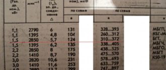
Dimensions
The main dimensions are as follows:
- diameter from 5.5 mm to 80 mm;
- meters per ton from 5362 m to 101.4 m;
- weight per meter from 0.1865 kg to 9.865 kg.
How to convert meters to kilograms?
Let's look at an example. Initial data : the standard project indicates that for the construction of a residential building we will need 1250 linear meters of AIII reinforcement with a diameter of 10 mm . Let's use the data from the table above and apply the following conditional formula:
P = M x L/1000 , where
- P—weight in tons;
- M—weight of 1 linear meter in kg;
- L is the total length of the reinforcing bars in m.
So, P = 0.617 x 1250/1000 = 0.771 tons, this is exactly the amount of class AIII reinforcement with a diameter of 10 mm that we will need for construction; when purchasing material, we must multiply this figure by the trimming factor (1.05 - 1.15).
How to convert kilograms to meters ? Given: 7.5 tons of AIII reinforcement with a diameter of 22 mm - you need to find out how much it will be in linear meters. Let's apply the inverse formula:
L = P/M , we calculate: L = 7500 kg/2.984 kg⁄m = 2513 linear meters.
Where is it used?
Construction reinforcement is widely used as part of monolithic and prefabricated reinforced concrete structures, strengthening concrete and improving its strength and performance characteristics . Technology is indispensable in the construction of private houses, shopping centers, industrial buildings, and power line towers.
As part of one structure, different rods perform different tasks. Based on the method of operation, they distinguish between working, distribution, mounting fittings and clamps.
The working rods take on external loads , the own weight of the structure.
Distribution rods hold the working reinforcement in the designed position and distribute the load .
Mounting rods and clamps are used to assemble frames .
Storage on site
Storing reinforcement on a construction site requires increased requirements ; we list some features:
- a flat, dry area with dimensions suitable for the length and amount of imported material;
- it is necessary to calculate in advance the consumption of reinforcement in accordance with the work schedule and link the volume and frequency of supply of materials to it in order to ensure uninterrupted installation work;
- prepare a covering material such as polyethylene film or tarpaulin to prevent precipitation from coming into contact with the reinforcement (the metal is susceptible to corrosion, which will further slow down the work and affect the quality);
- order or prepare at the site itself spacers from strong boards/bars or small logs; when storing, you need to rearrange the bundles of reinforcing bars as often as possible for more convenient unloading or loading;
- if possible, arrange a canopy , for example, from corrugated sheeting; it will interfere with unloading work, so it is better to make it removable;
- When delivering reinforcement to a site, you should immediately sort it by length, diameter and other parameters, storing it accordingly;
- Stacks with reinforcement must be made stable and low to avoid collapsing and falling on nearby builders;
- As a rule, a site for receiving and storing reinforcement is arranged next to the reinforcement shop for the convenience of reinforcement workers; the storage location can also be used for temporary placement of finished reinforcement cages and clamps.
Kinds
Construction fittings are classified according to the following characteristics:
- by material of manufacture : steel, composite;
- by production technology : hot-rolled rod, cold-drawn wire, reinforcing ropes;
- by profile type : smooth, corrugated.
Based on their location in the structure, longitudinal and transverse reinforcement are distinguished. Transverse rods improve the adhesion of the frame to concrete and protect against cracks in places near the supports. Longitudinal rods bear the main load and weight of the structure.
Composite construction reinforcement
Composite, or fiberglass, reinforcement is gradually replacing steel. Fiberglass wins in the following indicators:
- weight . For comparison, the weight of a linear meter of reinforcing rod with a diameter of 16 mm is 1.5 kg, a meter of composite of the same section will weigh 350 grams. The indicator reduces transportation and loading costs;
- corrosion resistance . Fiberglass is not subject to corrosion typical of metal and does not change properties in salt water;
- tensile strength . The composite material can withstand tensile loads 2.5 times greater than traditional steel;
- thermal conductivity Fiberglass rods increase the energy saving factor of the structure;
- durability _ The service life of the composite material is up to 100 years.
We recommend: Technical characteristics of chipboards and application in construction
The technical parameters of this fittings are regulated by GOST 31938-2012 .
Fiberglass meets modern requirements for radio signal transmission. In buildings whose walls are reinforced with composites, the Internet signal and telephone communications work without interruption.
For more information about the characteristics of fiberglass or composite reinforcement, see the video below; from it you will also learn in detail about the differences from steel:
Steel
Reinforcing elements are calculated at the design stage of the structure.
The cross-section, length of the rods and their number, as well as the mesh pitch and methods of connecting the frame and strengthening individual sections of monolithic elements are calculated by specialists of architectural bureaus in accordance with GOSTs and building standards, and are necessarily prescribed in the design documentation.
When choosing, all factors are taken into account, from the purpose and shape of the structure to the number of floors of the building and the structural design. In low-rise and private construction, A3 class reinforcement with a diameter of 8-16 mm is common.
Composite
The modulus of elasticity of the composite is significantly lower than that of metal. Fiberglass reinforcement is used with caution in floor slabs; if the cross-section is insufficient, it can bend. There are no special requirements for foundations or seismic belts.
The disadvantage of composite rods is the flammability of the material, as well as the complexity of installation.
Watch a video on choosing composite reinforcement and how it is tested for strength:
Reinforcement of reinforced concrete elements improves the quality of construction.
Which reinforcement material is better? Fiberglass or traditional steel? Let's discuss in the comments!
What is construction reinforcement, what is it used for and where is it used? Production, characteristics, types and selection criteria Link to main publication
Source: https://DomaVlad.ru/materialy-tehnologii/armatura-stroitelnaya.html
Use of reinforcement in construction and product characteristics
Rolled metal is used in any construction industry. It is absolutely indispensable in reinforced concrete structures. It is based on metal rods called reinforcement.
Reinforcement classifications
According to the manufacturing method, the fittings are:
- Rod, produced by rolling;
- Wire, obtained by cold drawing of rods;
- Ropeway.
According to the installation method it is divided into:
- Piece;
- Grid;
- Construction;
- Frame.
According to their appearance, the fittings are distinguished:
- Round;
- Smooth;
- Corrugated;
By appointment it happens:
- Working;
- Constructive;
- Assembly room.
Working fittings are considered basic. It is calculated on the perception of tensile and compressive forces of structures. Structural ensures the integrity of the object, that is, it is responsible for the strength of structures, redistributes the load over a large area, and also takes on shrinkage and temperature stresses. The assembly room has no static purpose. It serves for ease of installation and creation of a rigid frame. Its function can be performed by structural and working reinforcement.
Pros and cons of fittings
The fittings are easy to manufacture and therefore have an affordable price for most consumers. This factor is probably decisive when choosing; buyers prefer proven steel to plastic, despite its lightness and anti-corrosion properties.
In construction, especially monolithic construction, structural strength is crucial. Rolled metal is resistant to bending and stretching, and has toughness, which allows structures to withstand high loads without causing destruction of buildings and structures.
It is no secret that metal reinforcement rusts, reducing its original strength. But for severe operating conditions, reinforcing materials are made from alloy steels. The special material will last for several decades in an aggressive environment until its strength decreases by at least 5 percent.
The conclusion suggests itself that high humidity is not so harmful for metal fittings. Hidden in concrete, reinforced steel is completely protected from external influences. Perfect for foundation. Does not require additional protection if individual rods do not extend beyond the concrete monoliths.
During construction, it is necessary to accurately measure the reinforcement. An extra couple or three centimeters peeking out from a concrete structure is guaranteed to ensure contact of the metal frame with air or other aggressive environmental substances. Therefore, accurate calculation when making a frame is not greed, but practicality or foresight of the owner.
Application of reinforcement in construction
Reinforcement has no boundaries. The versatility of reinforcement lies in the fact that it is applicable when laying foundations, erecting walls, and constructing floors with reinforcement grids that provide additional load-bearing capacity.
Flexible reinforcement in the form of frames, welded mesh, and rods is used to increase the strength of concrete in the production of reinforced concrete structures, which are used in road, industrial and civil construction. Rigid reinforcement from angles and channels is used for the production of heavy concrete.
Its use is advisable in monolithic foundations and long-span floors, for the construction of columns of the lower floors of buildings with a large load. In the middle part of such columns, the role of rigid reinforcement is played by a package of welded metal sheets.
Steel used for the manufacture of rolled metal
In the production of fittings, steel of different grades is used, which then determines the main properties of the finished products. alloying additives and carbon are indicated when marking steel. The first two numbers indicate the amount of carbon. Next, a letter is written indicating the alloying additive and the percentage of its content. The most common alloying additives are:
- G – manganese;
- C – silicon;
- C – zirconium;
- X – chromium;
- T – titanium.
A striking example is the 25G2S brand; 20ХГ2Ц; 23Х2Г2Т.
The reinforcement is divided into classes taking into account the mechanical composition of the steel, which makes it possible to set requirements for the steel grades being developed. The class of reinforcement is established based on tensile strength, at the same time ensuring at least 95% of the yield strength. It depends on the manufacturing technology of metal products.
Reinforcement classes
Rod is considered to be reinforcement with a diameter of 6-80 mm, regardless of the type of delivery: in coils, coils or rods. There are:
- A – hot-rolled GOST 5781 and thermomechanically strengthened GOST 10884.
- B – cold-deformed.
Rod reinforcement is divided into classes:
- Hot rolled (A) with smooth and corrugated profile with a diameter of 3-80 mm;
- Thermo-mechanically strengthened with a diameter of 6-40 mm;
- Reinforced by hood.
Wire reinforcement:
- Intermittent profile with a diameter of 3-12 mm;
- Rope with a diameter of 6-15 mm.
Class designations are supplemented with the necessary indices:
- At – thermomechanically strengthened;
- Ac - special purpose - northern;
- C – weldable;
- K – corrosion-resistant.
The corrugated profile implies the presence of two longitudinal ribs and transverse protrusions that wrap around the round rod in a spiral in three passes. Profiles of small diameters of 6 and 8 mm have protrusions that run along one or two spirals, respectively. Reinforcing steel of classes A300(A-II) and Ac300(Ac-II) has protrusions that run in spirals with the same approach on both sides of the profile. Ribbed protrusions on the rod reinforcement, reefs and dents on the wire reinforcement - make the adhesion to concrete stronger.
Operating and work conditions, along with the type of structure and the presence of prestress, influence the choice of reinforcing steel class. Some are suitable to be tensed, others not to be tensed.
Structural reinforcement of classes A400, A400v, A500, At500s, A500s are used in lightweight concrete. In cold climatic zones, the production of structures with reinforcement should be carried out in heated rooms, with amendments made to the values of the corresponding coefficients. When the temperature drops below 30 degrees, in addition to the reinforcement class, the steel grade is indicated. Reinforcing steels of class A240-A300 are considered soft-plastic; mounting loops for prefabricated structures are made from them.
Dimensions and markings of fittings
Reinforcing steel comes in rods 6-12 m long, in special cases the length can be 5-25 m. For small diameters (up to 8, 10, 12 mm for different classes) it comes in coils. Markings are placed on metal products if they are not packaged, and on labels when packaged in rolls, bundles, skeins, as well as bundles of skeins or stacks of rolls. It is applied by impact - manual or machine, electrography, sticking labels from waterproof films, colored varnish, paint.
Source: https://rumpus.ru/dizajn-i-stroitelstvo/ispolzovanie-armatury-v-stroitelstve/
10. Reinforcement for reinforced concrete, its purpose. Working and installation fittings. Reinforcing products
Reinforcement for reinforced concrete structures. Reinforcement in reinforced concrete structures is installed for the purpose of: perceiving tensile stresses, strengthening the compressed zone of bending and compressed elements, to perceive shrinkage and temperature stresses.
Reinforcement installed according to calculation is called working reinforcement; reinforcement installed according to structural, technological or other requirements is called installation or structural.
Mounting reinforcement absorbs forces not taken into account by calculation from shrinkage and creep of concrete, temperature changes, ensures the design position of the reinforcement, as well as the strength of elements during manufacturing, transportation and installation. The fittings are rigid in the form of rolled profiles - I-beams, channels, angles, etc.
and flexible - in the form of rods, wire and products made from them. Flexible fittings are divided into: According to manufacturing technology (hot-rolled 6-90 mm), cold-drawn (3-8 mm). By the method of hardening (thermally strengthened and stretch-strengthened). By the shape of the surface (smooth and periodic profile). According to the method of application (tensioned and non-tensioned).
11. Mechanical properties of reinforcing steels. Tensile diagrams of reinforcing steels. Basic chart parameters
Reinforcing steels must have ductility, weldability, strength, resistance to cold brittleness and red brittleness. For mild steels εlim= 25 - 30%σ02= 300 - 400 MPa; σlim= 500 - 600 MPa; For hard steels εlim= 6-12%; σ02= 500 – 1500 MPa; σlim= 600 – 2000 MPa; Hard reinforcement steels are used only in structures with prestressed reinforcement.
12. Reinforcement products. Reinforcement connections. Anchoring of prestressed and non-prestressed reinforcement. Stresses in reinforcement in the anchorage zone
Rigid: in the form of rolled profiles - I-beams, channels, angles; flexible - in the form of rods, wires and products made from them. Spatial frames are assembled from several flat ones using connecting rods. The ratio of the welded rods should not be more than 3, in order to avoid lack of penetration or burnout of the rods. The lateral protective layer must be more than 10 mm.
at h15mm. At h=>250mm. The distance between the rods should ensure high-quality concreting of the element throughout the entire volume. There are heavy and light meshes. Light mesh has a diameter of longitudinal rods of 3-12 mm, transverse 3-10 mm, width 800-3800 mm, length up to 12 m. Heavy mesh has a diameter of longitudinal rods 14-32 mm, transverse 6-14 mm, width 1050-3050 mm, length up to 9 m.
Anchoring of reinforcement consists of securing the ends of the reinforcement in concrete using special devices or by launching it beyond the design cross-section for the length of the anchorage. Length of anchorage of non-prestressed reinforcement: σs=xRs/lan;lan=wan-σsp/Rbp+ ∆λan;wan= 0.25-0.7; ∆λan= 10-11. For prestressing reinforcement, length of anchorage zone: lan=wan-Rs/Rb+ ∆λan;wan= 0.5-0.8; ∆λan= 16-18.
13. The essence of prestressed reinforced concrete. Methods and methods for creating prestress
Prestressed structures are those in which, before the start of operation, compressive stresses are created in the tensile zone of concrete. Goals: 1.↓steel consumption through the use of high-strength reinforcement; 2. crack resistance; 3.stiffness and ↓deflections; 4. Compression of joints of prefabricated structures; 5. ↓concrete consumption and ↓weight due to the use of high-strength concrete; 6.Endurance design. Methods for creating prestressing reinforcement.
1. Tension of reinforcement on stops (before concreting the product). High-strength material is passed into the appropriate formwork or form with already installed frames, meshes, embedded parts, etc.
reinforcement, which is subsequently tensioned using various devices. The reinforcement is tensioned to the established level σsp and concreting is carried out. When the concrete gains sufficient strength Rbp (transfer strength), tension release is performed. The reinforcement, trying to contract to its original position, compresses the hardened concrete, but itself remains in an extended state. The transfer strength of concrete Rbp is the strength of concrete at which tempering is allowed.
2. Tension of reinforcement on concrete (after concreting the product). Channel formers (removable or non-removable) with reinforcement placed in them are placed in the formwork or mold, with installed frames, nets, embedded parts, etc., and concreting is carried out.
When the concrete gains sufficient strength Rbp (transfer strength), high-strength reinforcement is tensioned, thereby the hardened concrete is compressed, and the reinforcement remains in a stretched state.
Methods of creating prestress: mechanical, electrothermal, combined, physical and chemical.
Source: https://studfile.net/preview/6469800/page:7/
Vulture fittings: types and tasks, selection and application, installation features
Every experienced electrician knows that to connect a consumer to a self-supporting line, a self-supporting insulated wire is required. It is impossible to solve this problem without specialized fittings. It is necessary to provide support for the electrical wire along its entire length. In addition, only with its help can you securely fix the electrical cable to a wall or support.
If the installation of a self-supporting wire is carried out without the use of suitable fittings, then subsequently it will be impossible to perform the following list of frequently encountered tasks:
- Connect the cable to the transformers;
- Protect the network from overloads;
- Create branches;
- Bring the electrical line to the consumer with its secure fastening.
Considering the scope of use of reinforcement for SIP wires, it becomes clear that it should be made only from neutral materials. In other words, its presence next to a person is allowed by current standards, since it is not capable of causing harm to his health.
Moreover, it is with the help of fittings that the highest level of safety can be ensured, because it reduces the number of accidents, and on top of that, it maintains the high service life of the electrical line.
Fittings for SIP wires and cables include many different elements - clamps, caps and lugs. And each of them has its own special purpose.
Application for installation
One of the most common types of reinforcement for SIPs is clamps, which come in several types: anchor, supporting, connecting and branch. In addition, insulated tips and insulating caps are distinguished.
- Anchor clamps. Designed to secure the line at a certain height. This fitting is universal because it can be used for fastening to any surface.
- Support clips. They are used when it is important to prevent the wire from sagging between the supports.
- Connecting clamps. A special type of fittings with which you can significantly speed up the process of installing SIP wires. These clamps allow you to connect two cables in just a couple of seconds. Moreover, the quality of contact is quite high.
- Branch clamps. The need for them arises when it is necessary to remove the wire.
By fittings for SIP wire we should understand the whole variety of devices used for fastening SIP wire on supports and facades of buildings, for connecting a consumer, when connecting to an underground power cable.
The SIP fittings produced today are specially designed for modern cable designs. If installed correctly, SIP fittings can last at least 40 years.
The fittings can be used even at low temperatures, with the exception of those areas where the temperature is below 200 degrees Celsius.
An improved version of SIP is the modification SIP2a. Its main differences are the following:
- Increased short circuit resistance;
- Possibility of mounting on the walls of a building;
- Possibility of creating branches in a connected line;
- Possibility of installation using universal suspension and tension fittings.
Common varieties
There are many types of fittings for securing SIP cables Next, we will consider only the varieties that are the most common and allow electrical input into a private house.
- Anchor bracket. It is used to fasten anchor clamps of SIP trunk lines. The device is made of aluminum alloy and is not subject to corrosion and low temperatures. Stainless steel banding tape is used to secure the anchor brackets.
- Branch clamp. Necessary to create reliable contact, ensured by the design of contact plates made of tinned copper, even with wires of small cross-sections. This type of fittings is used to connect conductors with a cross-section from 6 to 150 mm2 in a main line with conductors with a cross-section from 1.5 to 6 mm2 when supplying street lighting, as well as electrical input into the house.
- Anchor clamp. Using this device, insulated conductors can be fastened on branches to inputs up to 1000 V. The body of this fitting contains internal wedges made of thermoplastic, thanks to which a reliable connection is created with the wire cores without damaging its insulation. The fittings are made of weather-resistant plastic. The clamp loop used in the design is highly durable and is made of hot-dip galvanized steel.
- Intermediate clamp. A type of reinforcement used to attach the self-supporting SIP-4 system, which has two or four load-bearing cores, to intermediate or corner supports. Additional wires are laid along the clamp. The body of the fastening device is made of material that is not exposed to ultraviolet radiation.
- Hook. Type of fittings used to secure the main wire in a suspended state. The hook is made of galvanized steel and is mounted to the support using a pair of steel straps. Using a hook, conductors and cables are attached to wooden, reinforced concrete and metal supports, as well as to the surfaces of walls of buildings and structures.
Rules for entering the house
After the SIP cable has been connected from the overhead line to the wall of the house, the owner is faced with the question of how to properly bring it into the house? Is it permissible to do this using a SIP cable, or should it be a copper cable that must be brought inside the house, having first connected it to the main trunk wire? To give the correct answer to this question, you must first familiarize yourself with a number of regulatory documents. First of all, you need to refer to the PUE , where there is no indication that the SIP cable can be installed inside residential premises.
Another document GOST R 52373−205 states that SIP cable can be used exclusively for laying overhead lines. Although, if you carefully read clause 10.3 of this GOST, then the SIP cable can be laid along the wall of the building, but this must be done while observing the following requirement - laying the wire on combustible bases should only be done in a corrugated or cable channel.
Cable entry
Based on the above, it becomes clear how exactly it is necessary to introduce an electrical cable into the house. The first step is to install a sealable box on the facade of the house.
It must be outdoor rated and have a protection level of at least IP65. We already install a circuit breaker in it - two or four poles - it all depends on the voltage (220 or 380 V).
We connect a SIP cable to the machine , and from the machine we lead a cable that meets the requirements into the building.
For example, this could be a VVGng wire with a cross section of 10 mm2. The place where the cable enters the house must be reinforced with a plastic or steel pipe. For the machine, try to set the rated current to a level higher than the current of the machine, which is installed in your electrical panel.
Incorrect installation option
Another option is also possible - the cable is inserted into the building directly without installing a box with a circuit breaker on the facade of the house. This option is quite acceptable, even though it will be somewhat contrary to the rules.
Many electricians and companies resort to this method. Controlling organizations are also not against it; they accept this installation option without any comments.
Although, if you still want to protect yourself from possible problems, we advise you to choose the first input option.
Allowable distance
To ensure that no problems arise after connecting the house to the main power line, this must be done in compliance with certain rules. A SIP cable that was introduced into a house without taking them into account may one day lead to a fire and even electric shock to a person. If we turn to the requirements of the PUE, they list the following distances that must be observed when introducing a self-supporting insulated cable into a house:
- The branch support should be located no further than 10 m from the facade of the building.
- The overhead line support should be installed no further than 25 m from the facade of the building.
- The overhead line support should be located no further than 15 m before the branch support.
- The laid cables should sag in the overhead line span by no more than 6 m.
- Installation of cables on the facade of a building is permitted at a height of at least 2.7 m.
During the construction of a power line, it is necessary to strictly comply with the requirements of current regulations and standards that can affect the reliability of power supply. That is why it is necessary to be especially careful when choosing linear coupling fittings and calculating the parameters of the overhead line.
Mistakes can have very serious consequences. You can prevent or minimize their occurrence by remembering the following important nuances:
- Before making a final decision during the acceptance of an overhead line, it is necessary to rely not only on the results of a visual inspection of the already erected line, but also on the correctness of the installation, during which personal presence is required.
- To lay the main line, materials must be used that meet the requirements for the overhead line under construction.
- The installation team must have all the necessary equipment, tools and accessories available.
- Only trained personnel should be involved in the construction and maintenance of the highway.
- It is allowed to start laying a line only if you have a well-developed project in hand.
Wrong choice of clamps
In most cases, the need to refine an overhead line design that involves the use of SIP cable arises due to incorrect selection of piercing clamps. For example, when the recommended clamp was selected without taking into account the wire cross-section. As a result, it turns out that the clamp, which is designed to work with a cable of a smaller cross-section, is unable to pierce the insulation, as a result of which good contact with the conductor cannot be ensured.
If contact does occur, then a current greater than the value for which it is designed will pass through the clamp. This can ultimately lead to a breakdown on the line. Another situation is also possible when the clamp recommended for use in the project was selected without taking into account the material of the SIP cable. If this error is not noticed and corrected in a timely manner, it can lead to destruction of the conductor at the point of contact due to electrochemical corrosion.
Conclusion
To correctly connect the electrical main to the house, you must have certain knowledge in the field of electrical engineering.
After all, any mistake made both at the design stage and during installation work can result in serious consequences, including an accident.
It is known that electrical mains are laid using SIP cable, which is the most correct solution today. But it is impossible to perform this work efficiently without using suitable fittings.
The fittings for SIP cables are very diverse and include many different devices. Only a specialist can know about the features and purpose of each of them, who must lay the highway right up to its entry into a residential building or other object.
This work must be performed not only using a special tool, but also taking into account the requirements determined by the PUE. Otherwise, everything can end in serious problems for the owner - not only in terms of damage to health, but also sanctions from regulatory organizations.
Source: https://tokar.guru/metallicheskie-izdeliya/armatura/vidy-armatury-i-osobennosti-montazha-sip.html
Reinforcement for reinforced concrete (classification) ⋆ Build boldly!
Classification of reinforcement used for foundations and railways.
b. blocks. The purpose of the reinforcement is to strengthen the concrete structure, take on significant tensile loads or strengthen the reinforced concrete block during compression.
Definition
Reinforcement for reinforced concrete is rigid or flexible rods, networks or spatial frames made from these rods.
To improve adhesion to concrete, the rods may have periodic thickenings.
Reinforcing meshes and frames
Reinforcing frames and meshes are ready-made structures from reinforcing bars for the production of reinforced concrete elements. They can be either factory-produced or made on a construction site.
There are knitted or welded reinforcement frames and meshes.
Classification of fittings
Let's put in order what we know about the types of reinforcement for foundations and railways. b. blocks. You can focus on the purpose, location in the structure, conditions of use and the material of the reinforcement.
By purpose
- The working reinforcement absorbs tensile loads.
- Distribution (structural) reinforcement is designed to transfer the load evenly between the rods of the working reinforcement.
- Mounting fittings are used to combine working and distribution fittings into a single frame.
- Anchor reinforcement or embedded parts are needed for installation or assembly by welding of precast reinforced concrete structures.
By orientation
In relation to the direction of action of forces, reinforcement is divided into longitudinal or transverse. Longitudinal reinforcement prevents the formation of vertical cracks and tolerates longitudinal tensile loads well.
Transverse reinforcement prevents the formation of inclined cracks from shear stresses in the compressed zone.
According to application conditions
Reinforcing bars can be pre-tensioned (stressed) before concreting. This technology makes it possible to cover large spans, have smaller deflections of the floors and withstand large tensile loads without the formation of cracks.
Prestressed reinforcement in reinforced concrete structures can only be operational.
Typically, prestressed reinforced concrete is not used in private and low-rise construction.
Composite reinforcement
Reinforcing bars based on glass, basalt, carbon or aramid fibers, impregnated with a thermosetting or thermoplastic polymer binder and cured.
The growing popularity of composite reinforcement in private construction is explained by its light weight (ease of transportation) and resistance to corrosion.
Types of fittings
Types of fittings according to GOST 5781-82 differ in mechanical qualities, see table:
What reinforcement to use for the foundation
a – not recommended, b – suitable, c – suitable, but rare
In private and low-rise construction, it is recommended to use reinforcing rods of classes A300 or A400.
Externally, the fittings A240 have no corrugation, A300 has an annular herringbone corrugation, A400 has a crescent herringbone.
It is acceptable to replace steel reinforcement with comparable composite reinforcement.
The use of reinforcing bars of higher or, conversely, lower quality is not rational.
We recommend reading the article about calculating the reinforcement of your type of foundation.
Reinforced concrete reinforcement (classification) Link to main publication
Source: https://SmeloStroi.ru/klassifikaciya-armatury/
Installation of shut-off valves
Considering the responsible role, the complexity of the design and the considerable cost of the products, the installation of shut-off valves on industrial pipelines should be carried out only by high-class specialists. As practice shows, in such a process everything is important - compliance with the rules prescribed by the manufacturer, competent choice of connection location, methods of adjusting products.
Not only the return on investment, but also the safety of operating a new communication system (or a restored one, if the installation of shut-off and control valves is carried out under a repair program) depends on how responsibly the user approaches the work. What should be taken into account here?
Before installing shut-off valves
For many large projects, distributing the construction budget before work begins is the norm. In this scenario, the purchase of reinforcement products is made much earlier than their use. If this is your case, and the shut-off valves will be stored in a warehouse for some time before installation, you need to create appropriate conditions for them. You need to store it:
- in closed packaging;
- with low humidity;
- at temperatures from 5 to 20 degrees Celsius without sudden changes;
- without direct sunlight.
It is advisable to leave the original packaging sealed. This will eliminate the risk of dusty abrasives getting into the device. If the packaging has not been preserved, it is advisable to pack the device in another container. During long-term storage, metal parts should be periodically lubricated to prevent corrosion. The same applies to rubber seals: to prevent them from drying out and cracking, use silicone grease.
Stages of installation of shut-off valves
The process of installing shut-off valves is divided into 3 main stages: preparation, planning and securing the products. As part of the preparatory stage it is necessary:
- clean the pipeline - remove foreign objects and dirt manually or using a cleaning system (water, air);
- check the flanges for integrity and absence of defects;
- prepare the devices (print, inspect, if necessary, clean the housing).
Planning includes choosing a location for installing shut-off valves and mounting a check valve (it will ensure stability of the flow direction and prevent water hammer, which will greatly reduce the service life of the equipment). This type of device is placed strictly on a flat surface without turns or bends. There should be no cracks, pipe deformations or other defects at the installation site of the shut-off valves
Installation of shut-off valves is carried out in two ways - fixing on flanges (or other fastening methods) and welding. In the first case, it is important not to overdo it: excessive force can damage the case and other elements of the device. When welding, the device must be moved to the open position (in some cases, intermediate).
Basic Rules
At each stage there are rules for installing shut-off valves that must be followed for all types.
- Before installation, the shut-off valves must be cleaned with a brush (water, steam).
- When choosing a location, you should focus on the most level area, while:
- in order to avoid depressurization at the joining points, installation of shut-off valves on the pipeline at the bend is unacceptable;
- the area for installation work must be strictly straight and pre-cleaned from dust and dirt;
- the condition of the flanges cannot be in doubt (they need to be checked).
- During the installation of pipeline shut-off valves, you need to pay attention to the direction of the arrows - it must correspond to the current of the working medium. Welding work should be carried out by first moving the devices to open positions. The tightening of fasteners when installing shut-off valves without welding must be strictly controlled: it should not be excessive in order to avoid mechanical damage to the body and other parts of the device.
Accuracy is the main rule when carrying out installation operations. It is in such processes that expensive equipment or mounting flanges are most often damaged. The main risks are falling products from a height (promises a broken case and incorrect operation in the future), excessive pressure on the device during fixation (can lead to cracking and corrosion of the box or damage to the integrity of the seals, which will greatly reduce the service life of the products).
Rules for installing shut-off valves by type
Each type of product in a class has its own restrictions and recommendations. They are indicated in the installation instructions for shut-off and control valves provided by the manufacturer. Let's consider important points when working with the most popular options for reinforcement products.
Valves
When fixing the valves, it is important to ensure the safety of the structures themselves and their correct position. The devices are carried only on slings (hull strapping). It is impossible to carry the valve by the stem/steering wheel; this can lead to its damage and complete failure. During welding, you need to set the steel valve stem to the upper position. For some representatives of the class, it is very important to consider the correspondence of the arrows on the body and the direction of flow of the working medium.
Butterfly valves
Rules for installing shut-off valves of this type:
- careful tightening of connections (there is a high risk of damaging the gasket when tightening threaded fasteners);
- when welding - install the locking element in an intermediate position between “open” and “closed”;
- The diameter of the mounting flange is selected equal to the diameter of the pipeline.
Ball valve
When working with a ball valve, do not use pliers, a vice or other clamping tools. It is very easy to damage such devices. The tap is installed so that it does not bear the pressure of connected devices or the pipeline itself. Fastening force – up to 30 N.
Check valve
Installation of shut-off valves to control liquid flow is always carried out in strict compliance with the directions (marks on the body). In the case of a check valve, it is mandatory to comply with the installation clearances and take into account the pulsation mode.
Expert recommendations
The durability and safety of the pipeline depends on the correct installation of shut-off valves Therefore, there is no room for mistakes and shortcomings. The requirements for welding work must be strictly observed.
An important rule: to avoid breakage of structural elements of dimensional products, displacement of their gaskets or damage to seals, a foundation is built under them - a concrete slab is placed or a pour is made. In other cases, if this is provided for by the design or required by the safe installation of shut-off valves, other supports may be installed.
Excessive stress during operation of shut-off and control devices is the surest way to ensure their early wear. It occurs when the wrong location on the pipeline is chosen (deformations, turns, bends).
The stage of preparing the main components and systems for installation operations should not be underestimated. It is necessary to check the body of structures for the integrity of the anti-corrosion coating, deformations and other defects very carefully. The same applies to flanges and mounting area.
The most reliable way to eliminate the numerous risks of installation work is to entrust them to qualified specialists with sufficient experience and professional tools.
Source: https://snmash.ru/articles/204-ustanovka-zapornoy-armatury.html
Criteria for selecting reinforcement for the foundation
The basis of the house is the foundation, and it must withstand different loads. One of them is for bending. Unfortunately, hardened concrete mortar cannot withstand a large load of this type. The structure immediately becomes covered with cracks, which reduces the quality.
Therefore, a reinforcing frame made of metal reinforcement for the foundation is laid in the body of the concrete mortar. Its manufacturers today offer different brands, types and types, which are based on different production technologies. Therefore, the question of what kind of reinforcement is needed for the foundation is very relevant today.
Distinctive features
All metal fittings produced today are divided according to the following characteristics.
- View.
- Class.
- Brand of fittings.
Class and brands
What class of foundation reinforcement is best to use? Experts believe that it is not lower than class A 400, according to the old marking, not lower than AIII. Rods of the highest class are unprofitable from an economic point of view, while rods of the lower class have low characteristics that are not suitable for foundation structures.
According to production technology, steel reinforcement is made from different steels. Since we are interested in brand A 400, it is manufactured:
- Made from steel 35 GS - this is a structural low-alloy steel for welded joints.
- 25 G 2 S.
- 32 G 2 R ps.
In addition, in the marking you can find different letter designations, which have their own definition of one of the qualities of the material.
- “B” at the beginning of the brand is a designation of wire, at the end it indicates that the product is strengthened by drawing.
- "T" - thermally strengthened.
- “A” at the beginning is the rod view.
- “K” is a rope type, the same letter at the end means that the material is corrosion-resistant.
- “C” - electric welding can be used.
Separation by purpose
Since the reinforcing frame is a cage, the rods are installed in different planes. In some foundation structures, not all types are used, but this division of material is regulated by different SNiPs, for example, “Concrete and reinforced concrete structures.” So, based on these rules and requirements, a classification of steel reinforcement has been made.
- Working reinforcement. These are rods located along the laying of the strip foundation, or elements of the slab foundation grid.
- Transverse . These are horizontally laid clamps that connect longitudinal elements to each other.
- Vertical . Clamps connecting longitudinal rods together in a vertical plane. They are absent in a columnar foundation, as well as in a slab foundation. In the latter they are not present if the reinforced frame is a single-row mesh.
Material parameters
To finally find out which reinforcement to use for the foundation, you need to choose it correctly by diameter. This dimensional indicator is directly related to the purpose of the material in the frame structure.
- Transverse elements are made of rods with a diameter of at least 6 mm (this is the minimum diameter of the reinforcement).
- Vertical also 6 mm if the height of the structure is not higher than 80 cm, and 8 mm if the height of the frame is more than 80 cm.
The diameter of the foundation reinforcement used for the manufacture of clamps can be determined at the rate of 0.25 of the diameter of the working reinforcement. And the choice of material for the latter is determined by the area of the foundation and the type of its construction. Eg:
- When laying a strip foundation, reinforcement is laid at the rate of 0.1 of the base area under the house. It is taken into account that the length of the wall is no more than 3 m. But the diameter in any case should not be less than 10 mm. If the length is more than 3 m, then reinforcement of at least 12 mm is used.
- As for slabs, a coefficient of 0.3 is taken here under the same conditions.
That is, when calculating how much reinforcement needs to be placed in the foundation, these ratios and the diameter of the rods are taken into account.
So, to summarize and answer the question of what kind of reinforcement is best to use for the foundation of a house, we say unequivocally - class A 400, corrugated: with two longitudinal ribs and always with transverse projections. The latter pass along a helical line, it is three-way. And remember, you cannot connect rods of grade A 400 using electric welding. The connection is made with a knitting wire. If welding is required, then choose M 400 C.
about calculating the weight of reinforcement.
Installation rules
If all the selection points have been determined, then you can proceed to the installation of reinforcement in the foundation. First of all, you need to decide how the steel bars will be connected to each other. There are three options: welding, wire and overlap. Everything is clear with the first ones, but the third position requires clarification.
Essentially, this is laying reinforcement into the foundation in the form of a grid without fastening. The rods are stacked on top of each other alternately, which creates a fairly strong cage. This connection method can only be used when constructing a slab foundation, when the reinforcing frame is a single-row mesh. Let's face it, it's not the most reliable frame for a foundation. It is better to use wire or welding for connection.
As for the installation of reinforcement for the foundation itself, it all depends on the type of foundation structure.
- When pouring the slab model, the rods are assembled directly in place. They are laid out on the surface of the prepared pillow, where they are either tied or welded together.
- If the strip foundation is buried, then it is better to make a reinforcing frame outside the trench, and then simply lower the finished structure.
- If it is shallow, then assembly can be carried out at the installation site. Although it will be easier to assemble it on the side.
- The frame is installed ready-made in the well for a columnar foundation. This is a structure of three or four rods tied with horizontal clamps.
Please note that the frame must be laid in the body of the foundation. Therefore, stands are installed under it. For example, solid brick, metal profiles, stones and other durable objects and fixtures. You cannot use rusty fittings or other metal products for this.
There is one operation during the installation process that involves installing reinforcement in the corners of the foundation structure. Here the rods can be connected to each other, as in all other cases, or the rods can be bent at 90°, which will ensure the integrity of the frame. Because the fewer joints, the more reliable the system. Therefore, it is important to know how to bend foundation reinforcement.
How and on what to bend the rods?
For bending reinforcement, special machines are usually used: factory-made or home-made.
If the task is to bend a rod with a diameter of 6 - 8 mm, then this can be done manually. Thicker rods cannot be bent in this way.
Factory machines are expensive, even the smallest ones. Therefore, they are used in workshops.
Their design is based on either an electric motor with a gearbox, or a pneumatic, or hydraulic pump. Before bending the reinforcement on the machine, the diameter of the rod is set on the working part of the bending equipment so that the rod inside the clamp does not dangle.
But if the volume of construction work associated with the manufacture of the reinforcing frame is small, then it is better to make the device yourself. This relates to the question of how to bend the reinforcement? The simplest thing is a pipe dug vertically into the ground. A rod is simply inserted into it at one end, and the other must be pulled to bend the rod. You can get a bend by installing a profile between two trees. True, thick reinforcement cannot be bent using such methods.
Therefore, it is bent by heating, for which either gas welding or a gas burner (blowtorch) is used. But it should immediately be noted that this reduces the strength of the product.
Alternative models
In addition to steel products, the market today offers several varieties: polymer reinforcement, fiberglass.
All of them belong to the category of composite reinforcement. In the process of their production, basalt, glassy, aramid and carbon fibers are used.
They are impregnated with thermoplastic polymer fillers. Glass reinforcement is designated ASP, a material made from basalt fibers APB.
Composite reinforcement for foundations is not so widely used because it has low strength, four times that of steel. For example, steel A 300 can withstand 200 GPa, ASP only 45 GPa. The foundation cannot be reinforced with such material.
The main advantage of composite products is maximum corrosion resistance. They are used in fastening mortars, which are used, for example, for laying walls.
A wall reinforced in this way has increased strength and can withstand tensile loads well.