Wire connection diagram in the junction box
We carry out installation in a junction box
Correctly connecting the wires in the junction box is a significant factor in the reliability of your electrical network.
And if you consider that more than 50% of all connections are concentrated in distribution boxes, then this element of your electrical network of a house or apartment becomes especially important. At the same time, we must not forget about the clarity of the connection, as well as its maintainability.
Based on all this, let's look at distribution boxes in more detail.
Rules for installing distribution boxes
First of all, let's look at the rules for installing junction boxes. After all, the reliability of your electrical network depends on this. Moreover, these rules are quite logical and do not require major investments.
Location of distribution boxes in the apartment
So:
- First of all, remember that the junction box must be made of a material that matches the installation surface. So, on combustible surfaces, for example, wood, distribution boxes made of non-combustible materials should be installed. Usually it is metal.
- If the distribution box is mounted on a fireproof surface, for example, concrete, then boxes made of fire-resistant materials can be used. Usually, for these purposes, standard boxes made of special plastic are used, which are widely available in hardware stores.
- It is also worth remembering that, according to clause 2.1.22 of the Electrical Installation Code, a supply of wire must be provided at all branches and connections of conductors to ensure re-connection. The cost of following this rule will be mere pennies, but if it is necessary to reconnect, this reserve will become “golden”.
- It is also worth specifying the location of the distribution boxes. In general, it is not standardized, but they are usually located at the entrance to the room from the side of the door handle. The height of the distribution box is usually 10-20 cm from the ceiling. This allows you to protect it as much as possible from accidental touch and visually hide it.
Connecting various electrical receivers in the junction box
Now you can directly examine the connection of the wires in the distribution box. After all, it largely depends on the type of device being connected, as well as on the number of these devices. Sometimes it is advisable to create two or even three distribution boxes for one room rather than trying to fit all the connections into one.
Connecting group wires
First of all, we need to determine whether we have an end or pass-through junction box. Ideally, each junction box should be an end box.
A terminal box is a junction box that does not have wires connecting it to other junction boxes. A pass-through is a box that has such a connection.
The photo shows a walk-through junction box with an outlet connection
So:
- The end distribution box contains three cores of the power cable or wire from which the end consumers are powered.
Note! There should be exactly three of these wires for a single-phase network. Of which, one neutral wire, according to clause 1.1.30 of the PUE, must have a blue color, one protective grounding wire, which is designated in yellow-green color, and a phase wire, which can have any other color designation.
- The feed-through junction box has three supply wires, which are usually connected to the terminal block. The next distribution box is powered from the same terminal block. As a result, we get two wires connected to each other.
- Another possible option is if for one group the box is an end box, and for another group it is a pass-through box. Moreover, usually the wire for which the box is a feedthrough does not have any connections in it. It just runs along the box.
Connecting sockets
First of all, let's look at the connection of wires in the junction box at home when connecting an outlet. After all, this is one of the simplest connections.
Connecting a socket in a distribution box
- So, in the junction box we have three strands of the supply wire. As we have already said, this is phase, zero and ground, indicated by the corresponding colors.
- To connect the socket, we need to connect the wire going directly to the socket to the corresponding cores of the power cable. In this case, color coding should be observed.
Note! All connections in the junction box should be made using terminal blocks, soldering, crimping or welding. This is required by clause 2.1.21 of the PUE, which prohibits the use of twisting.
- If the connection is made in a pass-through junction box as in the video, then the connection can be made both with the supply cable and with a cable feeding another junction box. After all, thanks to the connection between themselves, they are one whole.
Switch connection
The wiring diagram in the junction box for connecting the switch is somewhat more complicated, but also quite simple and understandable. And even a two or three-key switch should not cause you problems.
Connecting a two-gang switch
So:
- First of all, we connect the switch. To do this, it is necessary to connect the wire leading to the switch input to the phase of the supply cable. We lead the wire from the switch output into the distribution box.
- Now we connect the lamp. First of all, we connect it to the neutral and protective power cable, the wires going to the lamp. After this, we connect the phase wire of the lamp to the wire coming from the switch terminal.
- As for two-, three- or even four-key switches , the same principle is followed here. The only difference is the connection of the phase wire from the switch terminal.
- If this is a chandelier with two operating modes , then it has two phase wires. We connect our outputs from the switch to them.
- If different lamps will be connected from the switch , then our instructions advise first of all to connect their neutral and phase wires. Then one phase wire from the switch terminals to each lamp.
Connecting the lamp and socket
But to connect an outlet with a switch there will be a more complex circuit. The connection of the wires in the junction box is a little more confusing in this case. But if you analyze the diagram completely, then there is nothing complicated in it.
Connection diagram for switch from socket
- First of all, using the method described above, we connect the outlet.
- Now we connect the neutral and protective wires of the lamp. This is done in the same way as with a normal connection.
- As for the phase wire for the switch, there can be two options. You can purchase a single product, a switch with a socket in which the connection has already been made. Or you can purchase a separate switch and a separate socket. In this case, you will make the connection between them yourself.
- To avoid wastage of wires, in this case it is advisable to connect the switch directly from the phase contact of the socket. We connect this wire to the switch input.
- The wire from the switch output, as with a normal connection, is brought out into the junction box. Here we connect it to the phase wire of the lamp.
Conclusion
As you can see, all types of connections in the junction box can be done with your own hands. The main thing is to be careful and not to confuse the phase, neutral and protective wires. The easiest way to do this is to follow the recommendations of the PUE. After all, the color designation will prevent you from twisting wires of different colors together. And this is almost a 100% guarantee of the correctness of your scheme.
Source: https://Elektrik-a.su/energii/v-zhilyh/shema-podklyucheniya-provodov-v-raspredelitelnoj-korobke-204
How to properly connect wires in a junction box - connection methods and diagrams
Junction boxes perform a very important function. They ensure the distribution of electrical wires between points of consumption, i.e. switches, lighting fixtures and sockets.
Connecting wires in a junction box
Have you decided to install the devices listed above yourself? Then you need to thoroughly understand the features and order of connecting cables, as well as the basic methods of connecting them.
For a better understanding of the process, this event will be considered in several stages: from preparing the necessary materials to connecting electrical appliances using the example of an outlet, a two-key switch and light bulbs. First, you will learn about the basic methods of connecting cables and the features of connecting the box.
Wire connection methods
There are several methods for connecting electrical wires. You can choose the most convenient and suitable option for your case.
Twist
Twist
Currently, connecting cables in junction boxes using the twisting method is prohibited - it is considered extremely unreliable compared to other existing options. By choosing twisting, you consciously accept all possible responsibility upon yourself.
How to properly splice and branch wires using twisting
The connection itself is extremely simple: approximately 10 mm of insulation is removed from the wires, and then they are carefully screwed onto each other. When connecting wires with a diameter of up to 1 mm, we perform at least 5 turns, in the case of twisting more “serious” cables - from 3 turns.
Crimping
Crimping tool
Popular connection option. It is performed using a special sleeve according to the size of the wire bundle. The sleeve material must also match the cable material.
To crimp the product, press pliers are used to crimp the sleeves. Craftsmen often try to perform crimping using pliers, but professionals recommend refraining from this option, because the connection will not be as reliable.
The work is performed in the following order.
First step
We remove the insulation from the wires, focusing on the length of the sleeve used.
Second step
We twist the wires into a bundle and insert them into the connector.
Third step
We crimp the sleeve with the wires using press pliers.
Crimping process
Fourth step
We insulate the finished connection with heat shrink or regular electrical tape.
Crimping process
Welding
Welding
After making such a connection, you get essentially a solid wire, which is not afraid of either oxidation processes or other negative effects characteristic of detachable methods.
To connect wires using the welding method, you need to prepare the following:
- 24V welding machine with power from 1 kW;
- flux;
- carbon electrode;
- protective equipment (gloves, mask/goggles). Wire welding diagram
We work in this order.
Fifth step
Welding
We clean the resulting contact point from flux and cover it with varnish.
Finally, all we have to do is insulate the finished connection.
Soldering
Soldering
The procedure remains the same as when connecting wires by welding. The only difference is that the cables are connected using solder melted with a soldering iron. The molten solder should flow into the twist.
Important note! The connection is very reliable and durable, but professionals recommend refraining from using it in places where the cables can get very hot.
It is also not recommended to use soldering in areas of possible mechanical stress on the connection.
Screw terminals
Screw terminals
A great method for quickly and easily connecting wires in a junction box. Compact, inexpensive clamps allow you to connect both homogeneous and dissimilar conductors.
The job is done in two simple steps. You need to do the following:
- strip off approximately 5 mm of insulation from the ends of the wires;
- insert the wires into the clamp and tighten with a screw.
Important! Control the clamping force so as not to damage the integrity of the cores. Be especially careful when connecting aluminum wires.
Bolted connections
Bolted connections
The connection is reliable, but very bulky. Suitable for the same bulky old-style boxes. In a modern box, a bolted connection may simply not fit.
The work is performed in the following order.
Self-clamping connections
The most modern and popular option today. The clamps are extremely easy to use. In addition, such connections initially contain a paste that eliminates the risk of metal oxidation, which allows dissimilar conductors to be inserted into the clips without any fear.
We work in this order.
Self-clamping connections
First step. We remove approximately 10 mm of insulation from each wire.
Second step. Raise the clip lever up.
Third step. Insert the conductors into the connector.
Fourth step. We lower the lever down.
Clamps without levers simply snap into place.
Self-clamping connections
Studying the box wiring diagram
When connecting wires in a junction box, it is very important to know the specific markings of each cable. This will create a secure, reliable and generally correct connection.
Let's study the wiring diagram of the box. Connecting wires with grounding (PE)
Connecting wires without grounding (PE)
So, the “zero” wires (in the diagram they are blue) and the ground cables (indicated in yellow) are connected accordingly by color, as shown in the image. When arranging two-wire wiring, the circuit remains the same, only the grounding wires are excluded.
The phase desoldering procedure (indicated in black or red) is more complex. If only cables are routed through the box to connect the socket, the phase wires are also connected together.
Scheme in a junction box, two lamps
If cables go from the box to a switch with one button, then the wire that goes to the switch must be twisted with all the wires of the phase. The same cable that comes from the switch is connected to the phase wire going to the lighting fixture. As a result, 4 connections will be made.
Scheme in a junction box, two lamps and a group of sockets
In the case of connection through a junction box of a switch with two keys in conditions of three-wire wiring, a cable with four cores is connected to the chandelier. If the wiring is two-wire, the number of wires is reduced to three, because grounding is excluded from the circuit, as shown in the figure.
Studying the box wiring diagram
Without taking into account the separate twisting of the ground electrode, 4 connections are created in the box. All the “zero” wires (indicated in blue) are connected to each other.
The phases of the sockets and the power cable are twisted together and then connected to the common terminal of the switch with two keys. From the latter there are 2 separate wires going to the lighting fixture.
Thus, there is nothing super complicated about wiring the box. You just need to understand the peculiarities of the wire designation and the order of their connection. After this, you can begin to consolidate the acquired theoretical knowledge in practice.
Proper connection of wires in the junction box
The procedure for installing and connecting the distribution box
You are invited to familiarize yourself with the features of all key stages of connecting a junction box: from wiring to connecting electrical appliances.
The first stage - getting ready for work
Preparation of the workplace
First of all, we prepare everything that is needed to connect electrical appliances to the box. Set includes:
- cables 3x2.5, VVG;
- cables 2x2.5, AVVG;
- switch with 2 keys;
- fastenings;
- lighting;
- socket;
- round nose pliers;
- roulette;
- wire cutters;
- pliers;
- flat screwdriver;
- hammer.
Second stage - make the markings
Marking the working surface
At this stage, we mark the installation locations of electrical appliances and the routes for wires. This way we can calculate the required amount of materials for installing the system.
The third stage - we begin installation
Start of installation
First turn off the electricity supply.
We connect the wires to the junction box. As a rule, cables are laid in grooves. Small nails or special plastic staples are used to secure the cables. If the work is carried out in a wooden house, the wires will be supplied through special mounting boxes.
Important note! You should try to lay the wiring so that the cables do not intersect. If intersections are unavoidable, such places must be isolated especially carefully.
The fourth stage - we connect electrical appliances and connect the wires
Schematic diagram of connecting wires through terminal blocks
We insert approximately 10 cm of wire into a distribution box pre-built into the wall or fixed to the base (depending on the model). We remove the general sheath from the cables. Then we remove approximately 0.5 cm of insulation from each core. At this point, we focus on the situation - we remove enough insulation so that the cores can be connected in the chosen way.
The diagram shows an example of connecting electrical wires using terminal blocks.
In the example under consideration, the connection is made using a two-wire wire, in which one wire is a zero, the second is a phase. We connect the outlet and lighting fixtures to zero. We connect the phase supply wire to the socket and one core of the switch cable.
In our example, the switch is two-key. Each key is responsible for controlling a separate group of lighting fixtures. We connect the second wire of the switch cable to the first button, the third wire is connected to the second button.
The distribution box contains the neutral wires from the socket and light bulb sockets. The power cable is connected: zero is marked in blue, phase is marked in red. Wires are connected to connect each switch button to the light sockets.
Connecting wires
Connecting wires
Connecting wires
Fifth stage - checking the functionality of the system
We turn on the power supply and check the operation of our socket and switch. Everything works fine. We did a great job.
Checking the functionality of electrical equipment
Now you know the order of connecting the wires in the junction box and the connection features of each main electrical appliance. Using the information received, you will be able to independently cope with all planned events.
Good luck!
– Connection of wires in the junction box
Source: https://derevyannie-doma.com/poleznoe/soedinenie-provodov-v-raspredelitel-noy-korobke-video-shemy-foto.html
Connecting wires in a junction box: soldering, twisting, welding, etc.
Electrical wiring in the room must be safe and convenient to use. If you strictly follow this rule, then each energy consumer (chandelier, TV, computer, refrigerator) must have its own protection device against short circuits or overheating of the wiring. You can run a separate cable from the personal circuit breaker for each outlet and switch. Two more criteria oppose this: rationality and economy.
What are distribution boxes for?
Rational wiring looks like this:
That is, the total energy consumption of the facility is evenly distributed among the circuit breakers. In addition, consumers should be divided into groups, for example:
- Living room and bedroom lighting
- Kitchen lighting
- Lighting for bathroom and hallway
- Socket group (in each room)
- Power socket group (for powerful consumers, such as an air conditioner or an electric oven)
But with such a scheme, there may be many connections on one wiring line. It is not safe to make overhead connections and hide them in the wall. At a minimum, this does not make it possible to disable a faulty branch while leaving the rest of the circuit operational.
For normal distribution of lines, there are distribution boxes.
They are an insulated container, inside which switching (permanent) of electrical wiring lines occurs. The connection of wires in a junction box can be done in various ways, the main thing is to ensure reliable insulation between phases and a contact that can withstand the load.
The wiring diagram in the junction box allows you to save money when purchasing electrical cables, as well as avoid uncontrolled interweaving of wires in the walls. The so-called radial wires diverge from the shield with protective circuit breakers. On each of them there are connecting nodes: those same distribution boxes.
Important: The wire cross-section may be the same or different. The main condition: the power of the main cable cannot be lower than the power of the final wiring to the consumer (socket, light fixture).
In addition, there are certain methods and rules for connecting wires in a junction box. Let's talk about this in more detail.
General rules for switching electrical cables in distribution boxes
Of course, all requirements for energy supply are set out in the PUE.
This is an electrician's reference book. Moreover, there are fines for violating the Electrical Installation Rules. However, in practice, all these strictures apply only to institutions and organizations. In private households, responsibility ends with the wire coming out of the meter (electricity meter). The rest is up to the homeowner. To prevent an incorrect connection from leading to a fire or electric shock, you must follow simple rules:
- The connection of wires in the junction box is made during a complete power outage. Even if the electrician is wearing dielectric gloves and is familiar with safety rules, accidental contact of the phase wire with structural elements of the building or grounding is possible.
- The type of connection must be the same for each line within the same box. This will protect your line from loosening under load.
- Physical contact of conductors made of different materials (copper with aluminum) is not allowed. When electric current flows, active electrocorrosion occurs. Metals are coated with an oxide film, which impairs contact. The result is sparking, overheating, and complete burnout of the contact connection. If such a need arises, it is necessary to tin the wires using solder. After twisting, the connection must be soldered for at least 50% of the length. The rest of the strand will not corrode because no current flows through it under load.
- It is necessary to exclude the possibility of exposed conductors leaving the box. Even if the cable is completely laid in the wall.
- When connecting without contact devices, that is, using soldering, twisting or welding, an insulating cap must be placed on the exposed conductor. The insulator must be firmly fixed; non-combustible materials are used in its manufacture.
- The ends of the wires inside the box must have at least a 200% margin along the length of the connecting ends. In the event of a break or burnout, it will be possible to re-install without laying a new wire.
In addition, inexperienced electricians often make mistakes and break off wires when stripping the insulation. If the wire is inserted into the box under tension, reconnection will be impossible.
Methods for connecting conductors in a box
There is no single possible method. When choosing a way to connect wires in a junction box, an electrician weighs all factors: from the cost of materials to the expected load.
- Terminals. There is an opinion that this method is the most reliable, but this is a false statement. Most often, terminals are used on boxes with ready-made contact pads.
This connection of wires in the box allows you to disconnect one of the lines at any time (for example, for repairs) without causing damage to the entire power system. There are two ways to connect, directly to the block (by making a ring from a wire core), or using a terminal. With the ring everything is simple, you just need to ensure that the wire is laid in such a way that when tightening the threaded connection, the contact does not loosen.
But with terminals everything is more complicated. It is irrational to crimp a single-core wire: you can mechanically damage the conductor, and the core will break off at any moment. And when laid in a box, a single-core cable with terminals takes up a lot of space, and it is difficult to separate different phases at a sufficient distance.
An excellent result is obtained when crimping a multi-core soft cable; the contact terminal fits comfortably. But stationary installation of multi-core cable is nonsense.
Bottom line: Terminal blocks in the distribution box are convenient, but it is better to make the connection directly to the conductor under the screw, without using crimp terminals.
There are modern boxes with quick-installation contact blocks. This solution is really convenient, but is designed for light load.
Thus, the use of contact blocks is justified only if it is necessary to periodically disconnect one of the lines. And even then, sooner or later the conductor will break off.
- For standard wiring in an apartment (or household), the classics are still more suitable:
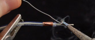
Welding wires in a junction box has been used since time immemorial. Anyone who repaired their Khrushchev or Brezhnev cars probably noticed a drop of solidified melt at the end of the aluminum strands in the boxes.
Today, the use of aluminum wiring is prohibited by the PUE, and the welding connection method is still popular. The point is this: after carefully twisting the stripped wires, the contact of the welding machine is briefly applied to the end point.
Usually this is a compact device of low power. It is used by almost all professional electricians. Works on the principle of a spot welding spotter. It will not be possible to light an arc, but the metal at the point of application melts properly. The figure shows the simplest circuit that can be assembled at home.
The connection quality is more than sufficient. In addition to the total twist length (40–50 mm), the ball at the end forms a point with minimal resistance. An additional plus is that this twist will not unwind even when moving the wires inside the box.
If a welding machine is not available, we limit ourselves to ordinary twisting. Of course, we make the connection not with our fingers, but with the help of pliers. All ends of the conductor must be stripped (but not reduced in cross-section), the length of the bare part before twisting begins is at least 70 mm.
Twisting is done after the wires are finally secured in the box. If the cable moves, the connection may become weak. The result is sparking, overheating, and contact breakage. It will be good if there is no fire.
- As an option, after twisting, the wires are soldered in the junction box.
Important! There is a widespread opinion among amateurs: under load, the twist will heat up and the solder will melt. Firstly: a load capable of heating a conductor to the melting temperature of solder is unrealistic at home. Of course, provided that the circuit breakers are in working order. Secondly: heating during twisting occurs due to loose contact, and this can be solved by soldering.
The reliability is not much worse than with welding. In this case, there is no need to purchase (do it yourself) a welding machine, a fairly powerful soldering iron, or even a hair dryer.
Tip: Use the most powerful soldering tool possible. It is better to expose the contacts to high temperatures for a short time than to heat the contacts slowly and for a long time with a weak heater.
During heating, monitor the condition of the insulation. If it starts to melt, take a break until it cools completely. Immediately after soldering, do not move the wire; allow both the solder and the insulation to cool.
Use refractory solders; these alloys have higher strength characteristics.
- Crimping. From the point of view of electrical conductivity, the quality of contact is no better than that of conventional twisting. But the strength of the connection increases significantly. If it is not possible to weld or solder the twist, crimp it using a special sleeve.
You can get by with pliers, but a special tool is still more reliable. There are bushings for parallel splicing of wires, and there are for fixing twists. There is no fundamental difference. If there are two or three conductors, parallel crimping is suitable. For larger quantities - crimping after twisting.
In fact, the methods discussed above are a modernization of the good old twisting. You should not be skeptical about the issue. Due to poor contact in the junction box, many fires occurred and damage to household appliances was caused. Therefore, when repairing electrical wiring in your home, use technical means to improve contact in the twist to the maximum.
Modern methods of connecting wiring in a box
The so-called quick fix pads. These products are widely offered in online stores and building materials markets.
Indeed, such devices make installation quick and convenient. The appearance of the connection is also pleasant. Therefore, such “electric clips” are loved by electricians who perform custom work.
However, this method has serious drawbacks. Let's make a reservation right away: the manufacturer does not promise high connection power: the characteristics are on the case. For an LED lamp, connecting a computer or TV - just right. But a refrigerator, electric stove, boiler cannot be connected through such a distribution box.
The contact area in such “quick releases” is small; the pad is connected to the conductor tangentially. With a light load, the current does not heat the surface too much. And when a serious consumer is connected, sparking, heating, and burning out of the connection will begin.
Methods for connecting wires in a junction box
There are quite a lot of ways to connect wires in junction boxes, when installing electrical wiring or simply extending electrical lines, but not all of them are allowed, and not all are equally reliable. At the same time, the rules for connecting single-wire and multi-wire wires, due to their design differences, differ.
First of all, when choosing a connection method, you need to refer to the PUE (Electrical Installation Rules), the main document regulating the installation of electrical wiring.
According to paragraph 2.1.21, from the 7th edition of the PUE:
Connection, branching and termination of wire and cable cores must be carried out using crimping, welding, soldering or clamping (screw, bolt, etc.) in accordance with current instructions approved in the prescribed manner.
The only thing I would add to this is the requirements of GOST R 50571.15-97, which does not recommend soldering wires when connecting, therefore, we will not consider this method. Our task is to choose only the most reliable and convenient methods; soldering, however, is not suitable for these parameters.
Squeeze
The clamping method is the most accessible way to connect wires. Its principle is quite simple: the conductive cores of cables or wires are pulled together, compressed, with each other using various types of connectors (screw, spring, etc.). The most striking representative of this method of connecting wires are terminals.
Terminals for connecting wires when installing electrical wiring are most often either screw terminals - where the wires are tightened in a common block with screws, or self-clamping - in which the wire wires are clamped between spring-loaded plates.
Screw terminals are most often used to connect electrical equipment; they are not used when connecting cables in junction boxes. One of the main disadvantages of a screw connection is that over time the contact weakens and the screw must be tightened. If this is not done, the connection point will begin to heat up and as a result, this may cause a fire or unstable operation of the electrical network.
Self-clamping terminals, based on a flat-spring clamp (fasteners under spring plates), are ideal for connecting cable cores or wires when installing electrical wiring. In order to connect the wires, it is enough to place the bare wires into the terminal connectors, where they will automatically lock and be connected to each other through the conductive material of the internal terminal mechanism.
And although such a connection is not as reliable as welding, it is used very often when installing electrical wiring. Primarily due to the simplicity and speed of installation. It is enough just to remove the insulation from the cable cores and place them in the terminals.
The main disadvantage of this connection method is the need to purchase high-quality self-clamping terminals. In addition, such connections manifest themselves rather ambiguously in many extreme situations that, unfortunately, can arise during the operation of the electrical network.
Experienced electricians try to use self-clamping terminals only for lighting groups, and connect cables going, for example, to sockets, by welding.
If you decide to do the wiring in your apartment yourself , then connecting with self-clamping terminals will be the most preferable option for you. The main thing is to use terminals specifically designed for switching power circuits and designed for this. Another advantage is that such connections do not need to be additionally insulated, which also saves a lot of time.
There are also terminals with a lever clamp, in which the core is fixed when the lever is closed, and when it is opened it is released again. Such a terminal can be used many times, but they are quite bulky and expensive, so they are rarely used for connections in junction boxes. Their main advantage over self-clamping terminals is the ability to connect stranded wires without additional preparation of the cores.
What is the best way to connect wires in a junction box?
Above are all the permitted methods by which you can connect electrical wires in a junction box when installing wiring in an apartment or house. Each of them has its own characteristics, strengths and weaknesses. Obviously, the choice should be made between two:
1. Welding of wires should definitely be considered first , because... This method of connecting wires guarantees maximum reliability of all wiring. If you want to be completely confident in your electrical network, and as you know, connections are the bottlenecks of any electrical wiring, I recommend renting, buying or assembling a welding machine yourself in order to be able to weld wires in boxes.
2. Connecting wires with self-clamping terminals is suitable for those who want to do the wiring quickly , while still obtaining a fairly high-quality connection. In this case, it is very important to correctly calculate the electrical wiring and not overload it. Many electricians, not just self-taught ones, have recently chosen terminals because of the simplicity and speed of installation.
I would recommend performing crimping only in cases where you already have specialized equipment (press jaws) and material - sleeves.
And if you know other convenient permitted ways to connect wires during electrical installation, leave a comment. In addition, write about your experience, which connection method and why you prefer. I think this will be useful to everyone! Just as usual, any comments on the topic, questions, discussions are welcome!
Source: https://RozetkaOnline.ru/poleznie-stati-o-rozetkah-i-vikluchateliah/item/160-sposoby-soedineniya-provodov-v-raspredelitelnoj-korobke
How to connect wires in a junction box
Let's assume that you are a bit of an electrician and decide to install or replace the wiring in your own house or apartment yourself. But if you don’t know any other way than to connect the wires in the junction box using simple twisting, we recommend that you familiarize yourself with this material. After all, there are many methods for reliable joining of contacts: welding, soldering, crimping, as well as the use of electrical connectors. Each of the options must be applied correctly and in the right place.
Soldering and welding of wires
Modern requirements set out in regulatory documents (PUE) prohibit splicing electrical wiring by conventional twisting, regardless of the insulation method. But if the twisted wires are soldered or welded, the contact will be reliable and will comply with all the rules.
Let's look at how to connect current-carrying parts of cables in a junction box using desoldering:
- Remove the insulation from the wires at a distance of about 3 cm and sand them with fine sandpaper.
- Twist the strands tightly together using pliers.
- Using rosin and solder (POS 61 brand is suitable), carefully tin the connection so that molten tin flows into the space between the wires.
- Insulate the joint with heat shrink tubing or wrap it with adhesive tape.
Note. Soldering copper is not difficult, but oxidized aluminum sometimes has to be treated with acid.
Connecting wires by welding is performed in the same manner, only instead of a soldering iron, a device with a carbon electrode is used. A special recess is made in it, into which flux is poured, after which the device is plugged into the network, and the electrode is pressed against the twist until an influx is formed in the form of a small ball.
The advantage of this method is the durability of the joint and the ability to connect wires of different sections, including multi-core ones, in the junction box. Due to its reliability, the connection is successfully used in power lines with various loads, but it has some disadvantages:
- Do not solder or weld copper conductors with aluminum ones;
- This connection is permanent and in case of alteration according to a new scheme, the contacting areas have to be bitten off.
Reference. Soldering contacts is often used when installing low-current networks, for example, telephone cables and radio points.
Disconnection by crimping method
In this case, the reliability of the connection of the wires in the junction box is ensured using sleeves made of the same metal as the conductors - aluminum or copper. To complete the job, you will also need special press pliers, shown in the photo.
Note. Some would-be electricians practice crimping sleeves with ordinary pliers, which is unacceptable. Correct fixation of contacts is carried out only with pliers.
Now about how to connect electrical wires in a box in this way:
- Perform termination and twisting of wires as described above.
- Place a sleeve over the twisted ends (it should be matched to the diameter and fit tightly).
- Crimp the sleeve with pliers in two places.
- If the distribution boxes are installed outdoors, the connection is insulated with heat shrink, ensuring tightness. PVC insulating tape can be used indoors.
This joining option has the same pros and cons as welding: you can connect wiring of different sections and numbers of wires, but you cannot connect contacts made of dissimilar metals.
Application of connecting terminal blocks
Terminals for quick connection of wires are of 2 types:
- screw clamps in the form of blocks;
- Wago type self-clamping connectors
The technology for splicing electrical cables using terminal devices is quite simple. The wires need to be exposed only 1 cm and inserted into the clamps. In the first case, the cores are fixed with screws, in the second - with levers or automatic latches. By the way, terminals with latches are disposable, while terminals with levers are used repeatedly.
We list the advantages of screw terminal blocks:
- Fast and reliable docking.
- Ability to connect copper wiring to aluminum.
- Provides a detachable connection.
- Does not require additional insulation.
One of the disadvantages of the pads is their size. It happens that when there is a large accumulation of wires coming from several switches or sockets, the screw connector does not fit inside the junction box. Point two: single-core wires are fixed without problems, but multi-core wires are flattened with screws, which is not good. Therefore, it is better to pre-tin such ends.
Wago clamps, which allow you to connect up to 4 wires of the same cross-section, have the same advantages as screw terminals, but take up less space. In this case, the operation of disconnecting the entire junction box will take about 5 minutes, which is very convenient for installing electrical wiring. Judge for yourself: the bare end needs to be inserted into the clamp with pliers until it stops and that’s all.
Reference. Similar devices are often used for laying Internet cables and other low-current networks.
Since there are cheap products on the market from various Chinese manufacturers, self-clamping terminal blocks have acquired a dubious reputation.
The fact is that in low-quality connectors, the contact weakens over time, causing them to overheat and melt.
If you purchased original Wago products, then there will be no problems; in other cases, it is better not to take risks and connect only lighting wires with clamps (power supply to switches, chandeliers, and so on). Wire the sockets using a different method.
The master will tell you how to use self-clamping terminals correctly in his video:
Plastic PPE caps
The abbreviation SIZ stands for connecting insulating clamp. It is a cone-shaped cap made of plastic, which contains a steel spring with an anodized coating.
The technology for using the product is as follows:
- Remove the insulation from the wires to be connected to a distance of 2-3 cm.
- Gather the wires into one bundle and insert them into the cap until it stops.
- Applying force from the blind part, turn the cap by hand 2-3 turns. A traditional twist is formed inside, secured with a spring.
Such clamps are quick-release and reusable, provided that the spring was not damaged during dismantling. With their help, the connection in the box is made quite quickly, does not require insulation and does not take up much space.
Important point. In order for the PPE cap to provide reliable and durable contact, it must be selected according to the diameter corresponding to the total cross-section of the wires being connected. For the correct selection, use the table:
Details on how to connect wires in a junction box in various ways, including using caps, are described in the video:
Conclusion
Now, knowing the features of all methods of connecting contacts in a junction box, you can choose the best option and successfully apply it. Finally, let us mention another old method of connecting conductors - bolted, when the conductors are bent around the thread to the right side and pressed with a nut. But this option is practically not used due to the inconvenience and cumbersomeness of the connection, although it is considered reliable and complies with the PUE.
Design engineer with more than 8 years of experience in construction.
Author and editor-in-chief of all articles on the website “qustu.com”. Graduated from the East Ukrainian National University. Vladimir Dal with a degree in Electronics Industry Equipment in 2011.
Source: https://qustu.com/kak-soedinit-provoda-v-raspredelitelnoj-korobke/
Junction box and what it is
All wires that supply electricity to a house or apartment come out of the electrical panel. Each room has several sockets and switches. To collect all the wires in one place and assemble a wiring diagram, junction boxes were invented. This is where they are connected for the further operation of all devices. For laying the wiring, established rules are used, described by the PUE, which stipulate the rules for laying wires and cables.
It also contains recommendations regarding the conduct of connections and branches of wires, specifically in the junction box.
According to these recommendations, the wires are laid along the top of the wall, at a distance of 15 cm from the ceiling surface. As soon as the wire reaches the turning point, it is lowered perpendicularly down, and the specialist installs a box at the branch point. According to this principle, all wiring cores are connected according to a given diagram.
Depending on the type of installation, the boxes are:
- internal, used for hidden wiring;
- external, used for external connection.
When installing an internal box, you need to make a hole in the wall, into which the box is then installed. When the cable is supplied and connected, the box is closed and the lid is flush with the wall surface.
In some cases, such a box is masked with wallpaper or a thin layer of plaster. If the thickness of the walls does not allow installing an internal box, then the only option is to install an external type box.
It is mounted on the wall surface, so complex preparatory work is not required.
Depending on the shape, the box can be:
The number of pins varies, in most cases there are 4, but sometimes there are more. Each terminal is equipped with a thread or fitting to which it will be convenient to attach a corrugated hose. The corrugated hose is designed for convenient location of electrical wires, so replacing a damaged cable will not cause difficulties even for a beginner:
- disconnect the corrugated hose from the junction box;
- disconnect from the socket or switch;
- pull a little;
- pull out;
- put another in its place.
If the cable was laid in a groove, then replacing it will be more difficult.
You will need to dig into the wall and remove the damaged cable, and lay a new one in its place. After such work, the wall will have to be repaired. The task of distribution boxes:
- Increase the maintainability of the power supply system. The accessibility of all connections allows you to identify the damaged section of the circuit. If all the wires were laid in corrugated hoses or pipes, then replacing damaged ones will not cause much difficulty.
- Providing free access to connection points. Since the majority of electrical problems arise from poor-quality or incorrect connections, you can easily check their condition by opening the junction box.
- Ensuring fire safety.
- Financial savings. By using a distribution box, you don't have to run a cable to each outlet.
Types of connections
The distribution box is designed to connect electrical wires. It doesn’t matter how this will be done, the main thing is that the end result ensures the reliability, safety and performance of all devices. Several methods are used to connect:
To determine for yourself the optimal method of connecting wires, you need to disassemble each of them and find out the advantages and disadvantages of each method.
Terminal blocks
These are plastic parts, inside of which there is a brass bushing with screws on both sides.
To fasten using this method, you need to insert the stripped ends on both sides of the block and tighten the screws with a little force. This method is not complicated, but you need to keep in mind that the pads come with different outlet holes, suitable for a certain wire cross-section size. Advantages:
- low cost;
- reliable connection;
- possibility of connecting aluminum conductors with copper ones.
Flaws:
- Such products are often found with poor quality, so it is difficult to talk about a high-quality connection.
- They allow you to connect only two wires to each other.
- Such blocks are not recommended for connecting aluminum and stranded wires. This is because aluminum is very brittle and the wires are very thin, so if the screws are over-tightened, the contacts may be damaged.
- Soldering can provide a more reliable connection.
connects wires by a clip
Spring terminals
This is a more modern invention, which has become an indispensable and effective assistant when performing such work. Unlike the previous version, a special mechanism is used instead of a screw, which allows you to carefully fix the wire without damaging it. The connection principle is very simple, the stripped ends are inserted into the holes of the box. You can find several models of these products on the market.
They come in disposable and reusable types. Disposable pads are intended for one-time use; if they are damaged and need to be replaced, the pads must be replaced with new ones, since the previous ones cannot be saved. They are not reused.
Reusable terminals cost a little more, but you can change wires and reconnect them using the same spring terminals.
Advantages:
- possibility of connecting wires made of aluminum and copper;
- the ability to connect several cores at a time;
- connecting a thin stranded wire without damage;
- compact dimensions;
- it will not take much time to work;
- high-quality connection;
- built-in indicator to monitor the operation of the electrical network.
The only drawback of such terminals is their high price.
PPE caps
Connecting insulating clips, this is how PPE stands for. People call them more simply, caps. Externally, they resemble caps made of plastic. There is a spring inside that holds the cores. Such products are most often used to fasten cores in junction boxes.
Advantages:
- affordable price;
- lack of possibility of fire, which is explained by the material of manufacture;
- quick installation;
- large selection of products in sizes and colors.
Flaws:
- insulation and fixation are not of high quality;
- connecting aluminum to copper is impossible.
Crimping with sleeves
This option is considered the most reliable. Its essence is simple: for joining, insert the stripped ends into a special sleeve and crimp. Finally, the sleeve is insulated. The arrangement of the wires can be any, from two stolons of the sleeve, or from one. In the first case, the junction of the wires should be in the middle of the sleeve; in the second case, the total cross-section of the wires should not be larger than the cross-section of the sleeve.
Advantages:
- high quality connection and insulation;
- low cost.
Flaws:
- Once a cartridge has been used, it cannot be restored; it is disposable.
- Availability of special tools: press jaws and pipe cutter.
- the presence of a special sleeve for fastening aluminum and copper cores.
- Installation work this way will require more time.
Soldering or welding
All experienced electricians recommend using welding or soldering. To connect several cores in a junction box, follow these steps:
- expose the ends of the wires;
- twist the prepared ends;
- solder the wires with a soldering iron or gas torch;
- let the solder cool;
- insulate the ends with electrical tape, heat-shrink tubing or cambric.
Please note that cooling ends with solder in water is strictly prohibited, as this may lead to deterioration in the quality of the bond.
Advantages:
- reliable and strong fastening of wires.
Flaws:
- availability of special tools and skills to work with them;
- complexity of the soldering process;
- permanent connection point;
- restrictions on some conditions of use, stated in the PUE;
Stranding and insulation
An old but effective way of fastening two or more wires.
The principle of work is simple: strip the ends and carefully twist them together using pliers. The twisting area must be insulated. Advantages:
- ease of operation;
- minimal material costs or their complete absence if you already have purchased electrical tape.
Flaws:
- not the best quality bonding;
- Aluminum and copper conductors cannot be connected.
- increase in twist resistance over time.
In most cases, this method is used when carrying out temporary electrical wiring, and cambrics are used for insulation.
At the moment, the PUE prohibits this method of connection because over time the twisting resistance increases and the contacts begin to heat up.
Walnut clamp
Fastening with a “Nut” clamp is used quite often.
This is a clamp with two plates and 4 screws at the corners. To fasten, you need to strip the ends of the wires, insert them into the plate and secure them with bolts. Place a carbolite shell on top. Advantages:
- low cost;
- no difficulties during fastening;
- connection of copper and aluminum conductors;
- high class insulation.
Flaws:
- such fastening requires periodic checking, and if loosened, the screws must be tightened;
- The dimensions of such a clamp will not allow it to fit into the junction box.
Using a bolt
Fastening with bolts is not only the simplest method, but also quite effective. All you need for the job is a bolt, 3 washers and a nut. The essence of the fastening is very simple, you need to put a washer on the bolt thread, screw on the protected core, again a washer on top, again a core, and another washer completes it. At the end of everything, the bolt is firmly tightened with a nut and insulated.
Advantages:
- minimal costs and easy execution of work;
- connection of aluminum and copper conductors.
Flaws:
- poor quality of fastening;
- high consumption of electrical tape;
- the bolt with electrical tape may not fit into the junction box.
What to do if there are several wires?
In a normal situation, you only had to connect two wires.
But what if there are several such wires? There are several solutions for this:
We have already told you how to connect the wires in the junction box, and which one you use is up to you. But experts advise giving preference to the first method, as it is the most effective.
What to do if the wires are of different sections?
For high-quality joining of wires with different cross-sections, experts recommend using spring or regular terminal blocks. Your goal is to firmly fix the wires with a screw. If the wires used are made of different materials, then to prevent oxidation you need to use pads with paste.
An alternative method of fastening would be to solder them.
How to connect stranded and solid wires
There are no special conditions for fastening such wires separately, so you can use any of the above methods. For convenience, we have given the advantages and disadvantages of each of them, so after studying them carefully, you can easily decide on the fastening method.
Source: http://electry.ru/elektromontazhnye-raboty/kak-soedinit-provoda-v-raspredelitelnoj-korobke.html
Why use a junction box
Wiring connection in the junction box
There are cases when, when installing electrical wiring, they neglect the installation of such distributors, considering that this is just a waste of time, since the box must first be installed, then the connections to it must be made, which will lead to additional difficulties. It’s easier to simply twist, insulate and simply plaster the wall. But here you need to think a little ahead, since in this case important points are missed:
- No free access to wires. For example, if the socket in your room does not work or the light has gone out, and after checking it turns out that the problem is a lack of voltage. How to check? Completely remove the trim? Tearing off wallpaper and plaster to get to the twist? This will ruin your renovation.
- If you want to install an additional outlet. It is not always convenient to connect it by laying wires from a previously installed outlet. Thanks to the distribution box, you can easily make new connections.
- The regulatory document PUE states that “places of connections and branches must be accessible for inspection and repair,” therefore the installation of such a distributor cannot be neglected.
- The absence of such distributors is contrary to fire safety standards.
As you can see, the distribution box plays an important role. But installing it is just the beginning. All that remains is to connect all the wires in it. What's the best way to do this? Let's look at some ways.
Crimping with a connecting sleeve
Cross-sectional crimping of copper wires
A fairly reliable method that will require the purchase of a connecting sleeve. You need to select it based on the diameter of the bundle being connected. Depending on the wires you connect, the material of the sleeve itself is selected.
For copper wires the sleeve must be copper, for aluminum wires - aluminum. To ensure a reliable connection, the sleeve is crimped with a special tool called press pliers.
This technology is quite effective and is included, along with other methods, in regulatory documents.
Crimping connection of aluminum wires
To connect this way you need:
- Remove the insulation, taking into account the length of your sleeve.
- Twist the wires into a bundle and insert them into the sleeve.
- Compress the sleeve using press pliers.
- Insulate the twisting area with heat shrink or insulating tape.
It is not recommended to use pliers in such work, since the connection will not be reliable enough. It is much better to buy press pliers or borrow them from good neighbors.
Soldering with a soldering iron
Soldering twists with a soldering iron
The method is very similar to welding, only in this case the wires are connected using solder. For these works you will need a soldering iron. To work you will need:
- soldering iron;
- fine sandpaper;
- rosin (flux);
- brush for applying rosin;
- tin-lead solder.
The operating procedure is the same as for welding:
- Removing insulation and cleaning with sandpaper.
- Twisting.
- Application of flux.
- Direct soldering. The soldering iron melts the solder, which should flow into the twist itself, reliably connecting the wires to each other.
Soldered wiring in the junction box with a soldering iron
Often copper wires are soldered using this method, but if you purchase special solder for soldering aluminum, you can also solder copper from aluminum.
Soldering is quite reliable, but is not recommended in areas where there may be strong heat. Moreover, under mechanical stress, the connection may weaken.
Using screw terminals
Connection of copper and aluminum wires
This method is fast, simple and effective. And most importantly, such clamps can combine dissimilar metals. For example, if you need to connect aluminum and copper conductors, which in itself, as you know, is contraindicated. These clamps are very simple and compact, and their cost may pleasantly surprise you.
Terminal blocks
To connect wires with clamps you only need to complete 2 steps:
- Remove 5 mm of insulation.
- Insert into the clamps and tighten the screw.
Melted terminal block contacts
That's all, as you can see, everything is very simple and fast. It is only important to control the force with which you clamp. If you tighten the screw too tightly, you may damage the wires. You need to be especially careful when working with aluminum wires.
Crimp lugs
The only disadvantage of a screw connection is that when working with a multi-core cable, it must be crimped with a special nozzle to ensure normal contact and integrity of the wire.
Self-clamping terminals
This method can be called the most modern, popular and easy to use. All you need is to buy special terminals at the store. Inside these terminals there is a special paste that prevents metals from oxidizing. Thanks to this, various metals can be inserted into such joints.
The work is as follows:
- 10 mm of insulation is removed from each wire.
- The lever, which is located on the clip, rises up.
- The conductors are inserted into the connector.
- The lever lowers to its original position.
If your clamps do not have levers, they must be inserted until the terminal snaps into place.
Connecting wires with a terminal block without levers
We have looked at the most reliable methods by which you can combine wires in a junction box. This is a very important stage of electrical installation work, since 70% of errors during the work consist precisely in incorrect connection of conductors.
But if you, even without experience in such work, use the methods given in this article, you can easily do everything in accordance with the requirements of the regulations. But which of these methods to choose depends on your capabilities and desires.
This video shows how to connect wires in a junction box:
You will learn everything about sleeving wires or crimping lugs from the material provided in this video:
Scheme
Box diagram
Switch and socket block diagram
Connection
Junction box connection diagram
Connecting sockets
Switch connection diagram
Junction box
Connecting wires
Wire connection diagram in the box
Source: https://kakpravilnosdelat.ru/kak-soedinit-provoda-v-raspredelitelnoy-korobke/
How can you connect the wires in a junction box?
The connection of wires affects the safety and reliability of electrical wiring. It is performed in different ways, using connecting devices and devices, depending on the characteristics of the wires.
Why use a junction box?
A distribution (otherwise a junction box, a branching box) is a type of installation box in which wire switching and electrical connections are made. It can be round, rectangular, square in shape, plastic, steel, fiberglass, aluminum in material.
The device is a container, the purpose of which, in any method of connecting wires in a distribution box, is to hide the branch of the electrical network. In addition, it allows you to effectively redistribute the load on networks and prevent short circuits in them.
There are many ways to connect wires in a junction box. The simplest one - twisting - was previously a priority. Today it is considered dangerous and unreliable. It was replaced by special connecting devices, devices designed for the various characteristics of the cables being connected.
Methods for connecting conductors
Correctly connecting the wires to each other means ensuring the reliability and safety of the electrical network. There are numerous types of wire connections. You can use long-used ones - twisting, soldering, bolting. It’s easier and faster to get the job done by using a cable connector - a special device that allows you to reliably connect cables of different diameters, single- and multi-core, from various materials,
Using Terminal Blocks
Blocks for connecting wires are a type of electrical installation products. They are called terminal blocks, terminals, terminal blocks, terminal blocks, KB, terminal clamps, terminal connectors. Contains 2 metal contacts or more. The latter have nodes in which cables are secured and are placed inside a dielectric housing, often sealed (filled with gel).
There are many types of terminal connectors. They are distinguished:
- by installation method: screw, detachable, push, barrier, pass-through;
- single-, double- and multi-row;
- for one-, two-, three-row and multi-tier cables;
- angular and straight;
- for single- and multi-core, flexible conductors;
- according to the method of wire clamping: screw, spring, knife, end.
Source: https://odinelectric.ru/wiring/wires/kak-soedinit-provoda-v-raspredelitelnoj-korobke