Surface mounting, use of chip (SMD) components
What are the advantages of using such chip elements? Let's figure it out.
The advantages of this type of installation
Firstly, the use of chip components significantly reduces the size of finished printed circuit boards and their weight, as a result of which this device will require a small compact case. This way you can assemble very compact and miniature devices.
The use of chip elements makes it possible to save a printed circuit board (fiberglass), as well as ferric chloride for etching them, in addition, you do not have to waste time on drilling holes, in any case, this does not take much time and money.
Boards made in this way are easier to repair and easier to replace radio elements on the board.
You can make double-sided boards and place elements on both sides of the board. Well, it saves money, because chip components are cheap, and buying them in bulk is very profitable.
First, let's define the term surface mounting, what does it mean? Surface mounting is a technology for the production of printed circuit boards, when radio components are placed on the side of the printed tracks; in order to place them on the board it is not necessary to drill holes; in short, this means “surface mounting”. This technology is the most common today.
In addition to the advantages, there are of course also disadvantages. Boards assembled on chip components are afraid of bends and impacts, because... after this, radio components, especially resistors and capacitors, simply crack. Chip components do not tolerate overheating when soldering. From overheating, they often crack and microcracks appear. The defect does not manifest itself immediately, but only during operation.
Resistors and capacitors
Chip components (resistors and capacitors) are primarily divided by size, there are 0402 - these are the smallest radio components, very small, such as are used, for example, in cell phones, 0603 - also miniature, but slightly larger than the previous ones, 0805 - used, for example, in motherboards boards, the most popular ones, then come 1008, 1206 and so on.
Resistors:
Capacitors:
Below is a table indicating the dimensions of some elements: [0402] - 1.0 × 0.5 mm [0603] - 1.6 × 0.8 mm [0805] - 2.0 × 1.25 mm [1206] - 3.2 × 1.6 mm
[1812] - 4.5 × 3.2 mm
All chip resistors are designated by code markings, although a method for deciphering these codes is given, many still do not know how to decipher the values of these resistors, in connection with this I have described the codes of some resistors, take a look at the table.
Note: There is an error in the table: 221 "Ohms" should be read as "220 Ohms".
As for capacitors, they are not designated or marked in any way, so when you buy them, ask the seller to sign the tapes, otherwise you will need an accurate multimeter with a function for determining capacitances.
Transistors
Mostly radio amateurs use transistors of the SOT-23 type, I won’t talk about the rest. The dimensions of these transistors are as follows: 3 × 1.75 × 1.3 mm.
As you can see, they are very small, you need to solder them very carefully and quickly. Below is the pinout of the terminals of such transistors:
The pinout of most transistors in such a package is exactly this, but there are exceptions, so before soldering the transistor, check the pinout of the terminals by downloading the datasheet for it. Such transistors are in most cases designated with one letter and one number.
Diodes and Zener diodes
Diodes, like resistors and capacitors, come in different sizes; larger diodes are indicated by a strip on one side - this is the cathode, but miniature diodes may differ in labels and pinouts. Such diodes are usually designated by 1-2 letters and 1 or 2 numbers.
Diodes:
Zener diodes BZV55C:
Zener diodes, like diodes, are indicated by a strip on the edge of the case. By the way, because of their shape, they like to run away from the workplace, they are very nimble, and if they fall, you won’t be able to find them, so put them, for example, in the lid of a jar of rosin.
Microcircuits and microcontrollers
Microcircuits come in different packages; the main and frequently used types of packages are shown in the photo below. The worst type of case is SSOP - the legs of these microcircuits are located so close that soldering without snot is almost impossible, the nearest pins stick together all the time. Such microcircuits need to be soldered with a soldering iron with a very thin tip, or better yet, with a soldering hair dryer, if you have one; I described the method of working with a hair dryer and solder paste in this article.
The next type of case is TQFP, the photo shows a case with 32 legs (ATmega32 microcontroller), as you can see, the case is square, and the legs are located on each side. The main disadvantage of such cases is that they are difficult to solder with a regular soldering iron, but it is possible. As for other types of cases, they are much easier.
How and what to solder chip components with?
It is best to solder a radio component chip using a soldering station with a stabilized temperature, but if there is none, then you can only use a soldering iron, which must be turned on through the regulator! (without a regulator, most conventional soldering irons have temperatures at the tip that reach 350-400*C). The soldering temperature should be about 240-280*C.
For example, when working with lead-free solders that have a melting point of 217-227*C, the temperature of the soldering iron tip should be 280-300°C. During the soldering process, it is necessary to avoid excessively high temperature of the tip and excessive soldering time. The soldering iron tip must be sharpened, in the form of a cone or a flat screwdriver.
Recommendations for soldering chip components
The printed tracks on the board must be tinned and coated with alcohol-rosin flux. When soldering, it is convenient to support the chip component with tweezers or a fingernail; you need to solder quickly, no more than 0.5-1.5 seconds. First, one lead of the component is soldered, then the tweezers are removed and the second lead is soldered. The microcircuits need to be very accurately aligned, then the outer pins are soldered and checked again to see if all the pins fit exactly on the tracks, after which the remaining pins of the chip are soldered.
If, when soldering microcircuits, adjacent pins stick together, use a toothpick, place it between the pins of the microcircuit and then touch one of the pins with a soldering iron, it is recommended to use more flux. You can go the other way, remove the screen from the shielded wire and collect the solder from the pins of the microcircuit.
Several photographs from my personal archive
Conclusion
Surface mounting allows you to save money and make very compact, miniature devices. With all its disadvantages that exist, the resulting effect undoubtedly speaks of the promise and demand of this technology.
Source: https://cxem.net/beginner/beginner95.php
How to solder SMD elements manually
Every day, radio amateurs are increasingly using SMD parts and components in their work. Despite their size, they are easier to work with: you don’t need to drill holes in the board, bite off long pins, etc. It is imperative to master the soldering of SMD parts, as it will definitely come in handy.
This master class is not intended for beginners in soldering, but rather for amateurs who are good at soldering but have a little difficulty soldering multi-legged microcircuits or controllers.
Will need
This is a minimal set, without expensive soldering stations, hair dryers and desoldering pumps.
We solder SMD parts with our own hands
So, let's start with the most difficult thing - soldering the controller in the QFP100 case. With chip resistors and capacitors, I think everything is clear. The main rule here: there is no such thing as too much flux, or you won’t ruin the soldering with flux. Excessive application of flux prevents tin from spreading abundantly over the contacts and shorting them. There is also a second minor rule: even a little solder can be a lot. In general, you need to dose and apply it to the sting very carefully so as not to overdo it, otherwise it will flood everything at once.
Tinning the site
Experienced electronics technicians don't always perform this step, but I recommend doing it in the first couple of days.
You need to tin the board, namely the place where the controller will be soldered. Of course, the site is most likely tinned, especially if the board was made in production. But over time, an oxide film appears on the contacts, which can hinder you.
Heat the soldering iron to operating temperature. Lubricate the area generously with flux. We apply a little solder to the tip and tin the tracks.
We remove excess solder using the PSH wire. It absorbs solder perfectly due to the capillarity effect.
Installing and aligning the controller
Once the site is prepared, it's time to install the controller. There is a trick here; most solders install the microcircuit and use tweezers to align its contacts along the tracks. But this is very difficult to do, since even a slight twitch of the hand throws the controller a considerable distance.
It will be much easier to do this if you grease the corners diagonally with flux paste.
Now we install the controller and adjust it with tweezers.
As soon as the microcircuit is installed, we solder the contacts diagonally.
We check that all contacts are in the right place.
Soldering microcircuit contacts
Here you can already use both liquid and viscous flux. We apply it very liberally to the contacts.
We wet the tip with a drop of solder. We clean off excess with a sponge.
And, carefully move along the lubricated contacts.
There's no need to rush.
Removing excess flux and solder
After soldering all the contacts, it's time to remove excess solder. Probably several contacts stuck together.
We wet the contacts very generously with liquid flux. We completely clean the soldering iron tip from solder with a sponge and go over the sticky contacts. Excess solder should be drawn onto the tip.
To remove excess flux, use SBS - an alcohol-gasoline mixture mixed 1:1.
We wet it generously.
And we wipe it.
Watch the video
Be sure to watch the video, where you can clearly see the movement of the soldering iron and all the manipulations.
Source: https://labuda.blog/125715
DIY thermal tweezers for SMD components
DIY thermal tweezers
Thermal tweezers are exotic until you start working with SMD. This is where the need arises. As a rule, when replacing (the desire to make money by removing “swag” from broken boards is hardly justified). Although. Although, to be honest, it is quite possible to clean off the left component with a “fork”.
But if you still can’t, then you need a subject.
And it is good, or at least acceptable, because “bad” in this case means “nothing” - very expensive.
“Pace,” for example, is somewhere around 40K for a soldering iron + the same amount for a station.
Although, to be honest, the motivation for this project was a little different. Working with network electricity. First experience.
Because the tweezers were designed to be adjustable.
So, take a regular soldering iron. Two. As it turned out later, cheap domestic ones are not the best choice for such a thing.
And almost immediately after meeting, part of the “guard” is bitten off from the soldering iron:
Next, to the best of the skill of the tentacles, handles are turned from scrap wood using available tools. The soldering irons are placed in these cradles (I would like to believe that they are perfect) and thoroughly wrapped with electrical tape.
Already something.
At the back they are fastened with a precision box loop, and at the front they are held back by a fairly soft spring:
And here you end up with Mozhaisky’s quadcopter, but it’s quite floating:
However, we still need to make stings. Why not? To the best of your imagination. For every taste.
You just need to note that they burn quickly. This is not Japanese fashion. (
Fixation in the pincer plane is desirable, but not required. If both tips have something to rest against on the board. This does not always happen. But quite often. The ease of soldering parts depends on the structure of the boards. Amateur - instantly. But with powerful polygons, multi-layered ones - depending on your luck.
But it's still possible.
As a result, the happy owner of the tweezers happily has a cleaned board.
Or maybe even parts.
Next. Naturally, there is a desire to control the temperature of the stings. This means that a circuit is needed. And it arose. My first circuit for a 220V network.
As a consequence of uncertainty (220!) - reinsurance with or without reason.
For example, a safety transformer for the period of assembly and debugging. A real harsh radio amateur, I am sure, does not know what this is. Reading this text, he just grins condescendingly.
Or - calculation of a resistor to control a triac. It is taken almost at the LOWER limit of the current. And the current there is not constant, but only at the moment of switching on (although it switches on at every period). And resistors for LEDs (although I use very sensitive ones). And radiators for triacs - they are not needed with such a light load. In short - 1001 reinsurance.
I thought that I had poorly described the diagram itself and added this piece; If I’m chewing on trivial stuff, just skip it. The MK (Arduino) controls the MOC3041 optocoupler (by the way, from the datasheet it also came with a 39 Ohm resistor with a 0.01 mF capacitor - to dampen the inertia of the triac “The 39 ohm resistor and 0.01 mF capacitor are for snubbing of the triac and may or may not be necessary depending upon the particular triac and load used". No safety net required. By the way, in the circuit from there the limiting resistor is generally supposed to be 360 Ohms, but I already regretted that). The program for Arduino is the simplest alternation of voltage and pauses, cyclically selected by pressing a button, displayed by colored LEDs on the demo layout - there are three temperature modes, where pauses are longer and heating is shorter. I don’t think anyone is interested in the code, everything is elementary there. For viability, of course, we also need to calibrate each of the soldering irons and introduce a correction factor. But I didn’t do this. The figure shows a diagram for one tip. For the other, it’s the same, but taking into account that the safety transformer is common to both halves. I don’t show the signet itself. Sorry, I'm just ashamed of the implementation
Source: https://morflot.su/termopincet-dlja-smd-komponentov-svoimi-rukami/
Top 10 useful devices and consumables for radio amateurs on aliexpress, part three / selections, listings, top 10, and so on / ixbt live
TOP 10 useful devices and consumables for radio amateurs on Aliexpress, part three. The topic contains useful devices and consumables (solder, fluxes), as well as proven radio components. Prices for most items are several times lower than offline stores.
The best solder Kaina:
Product link - HERE
One of the best solders with flux inside! There are several options to choose from, including reel diameter and weight. The soldering is of high quality and this is confirmed by almost everyone who has used it. It is not that expensive, but there is a tendency for prices to rise, so buy a spare. Personally, I only solder with it. Take it, you won't regret it!
High-quality inactive flux RMA-218:
Product link - HERE
One of the best inactive fluxes among inexpensive ones. Supplied in syringes with a needle for more convenient application to the surface to be soldered. It practically does not smoke, at least much less than the same “folk” rosin. You don’t have to wash it off, because... it is inactive, unlike the moderately active RMA-223. I’ll add on my own behalf that the flux is good, I bought it here.
Set of prototype printed circuit boards:
Product link - HERE
A set of cheap development boards for “quickly” building a project or testing its functionality. The set includes 20 different scarves. especially useful for Arduino lovers (programmers). The boards are double-sided; radio elements can be mounted on both sides. This solution is much more convenient and reliable than wall-mounted installation. The price is really low.
Printed circuit boards:
Link to product (getinax) - HERE
Link to product (textolite) - HERE
For more serious projects or ready-made (tested) solutions, it is better to purchase printed circuit boards. There are two types: from getinax (obsolete) and textolite. Getinax is smellier, less durable, but still widely used. Judge for yourself: getinax is paper impregnated with varnish, and textolite is fabric impregnated with epoxy. Getinax does not withstand high temperatures and changes, it can swell and bend.
Set of SMD resistors:
Product link - HERE
A convenient set of SMD resistors in the form of a book. All denominations are sorted and signed. This is much more convenient than a box with a bunch of bags or, even worse, matchboxes. The seller has several standard sizes, as well as other SMD elements (capacitors, chokes). The sets also differ in the number of elements in them.
NICHICON Low ESR Electrolytic Capacitors:
Product link - HERE
I recently bought several different types of capacitors, seemingly original ones. The internal resistance is normal, the capacitance is adequate. The seller has a large selection of models, you can choose any. A lot usually includes 10 or 20 pieces. Check with the LCR-T4 component tester or analogues for $5, I gave a verified link in previous collections.
Another trusted Conder seller - HERE
Most denominations are presented on one page.
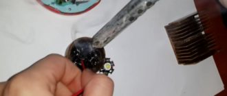
Thermal pad:
Product link - HERE
An equally necessary thing when assembling or repairing equipment. The thermal pad has heat-conducting properties, but does not conduct current. This allows you to mount several elements, such as transistors, on one heatsink. Suitable for repairing laptops and tablets. Allows you to easily remove heat from memory chips. I've been using this thermal pad for a long time, no complaints.
Hot melt adhesive (3 tubes):
Product link - HERE
An alternative to thermal pads with its pros and cons. Pros: better heat transfer, ease of use and greater efficiency. The only downside is that it sticks tightly. To disconnect the radiator from the chip you will have to use several “folk” methods, otherwise there is no other way. And it’s so simple: degrease, spread and glue. Lot of three tubes.
Source: https://www.ixbt.com/live/topcompile/top-10-poleznyh-prisposobleniy-i-rashodnikov-dlya-radiolyubiteley-na-aliexpress-chast-tretya.html
Soldering SMD components at home
Read all news ➔
Over the past few years, surface mount radio technology has become very popular and is used in the production of most modern electronic devices.
The abbreviation SMD stands for surface mounted device, which in turn can be translated as “surface mounted device”.
Actually, the very name of this technology fully reveals its essence - radio components are mounted directly on the surface of the board, but unlike wall-mounted components, SMD components do not require special holes for mounting.
The absence of special holes for installing radio components made it possible to make printed circuit boards more compact. The use of surface mount technology can significantly save space on the board, which in turn allows you to increase the density of radio components and make more complex devices.
In addition, most SMD components are miniature in size, due to the fact that they do not require large pins like lead components. But many people mistakenly believe that all SMD components, without exception, are very small. Among them, quite often there are large radio components that differ from their “lead” counterparts only in the type of conclusions (which is logical).
But let's move on to the essence of the article, namely the question of how soldering of SMD components is carried out and whether it can be done at home.
SMD and regular electric soldering iron
Quite often, in small-scale production or the production of device prototypes, specialists use conventional electric soldering irons. How to solder SMD components using a contact soldering iron?
1. First, flux is applied to the place where the component is to be installed.
2. Next, the component itself is installed, which needs to be soldered.
3. Apply a little solder to the soldering iron tip. The main thing is not to overdo it and not to apply too much.
4. A drop of solder is applied to the contacts of the component. Thanks to the flux, the solder spreads well and securely bonds the component to the contact on the board.
If there is too much solder, the soldering area will be sloppy. Excess solder can be easily lulled with a special tape, or simply with the tip of a soldering iron.
To solder SMD components with a regular soldering iron, it is better to replace the standard tip with a thin one. If this is not the case, you can use the standard one, but before starting serious work you will need a little training.
The advantages of this method are its simplicity. If you have a regular soldering iron, then nothing else is needed besides it. The disadvantages are also obvious - the operating speed will be quite low (especially if you do not have SMD soldering skills).
Soldering using a hot air soldering station (hair dryer)
This method is also often used in small-scale production and repair. At the same time, the quality of soldering will be much higher than when using a conventional soldering iron. Soldering with a hot air soldering station or hair dryer occurs as follows:
1. Special solder paste is applied to the board.
2. An SMD component is installed that needs to be soldered.
3. The component and soldering area are heated with a hairdryer. At the same time, the flux evaporates from the solder paste, and the smallest grains of solder melt and spread, soldering the component to the board contacts.
The advantages of this method are a neat place for soldering the component to the board and the simplicity of the entire process. The main thing is not to apply too much paste. In this case, it is not always necessary to apply an additional portion of flux, since it is already contained in the paste.
There is only one disadvantage of this method - a hot-air soldering station can be quite expensive. Also, the air flow does not act pointwise, but on a specific area. If you do not install a nozzle for working with miniature SMD components, there is a high probability of heating and melting the solder on already soldered components.
Soldering with an infrared soldering station
Implementing this type of soldering at home can be difficult since the entire process is carried out using an infrared soldering station. As the name implies, the flux is heated using infrared radiation. In this case, it is important to control the heating temperature, and you cannot do without heating the board itself. This is necessary to prevent it from deforming when heated with an infrared soldering iron.
There are many types of infrared soldering stations, among which you can find both amateur and professional ones, designed for work in small-scale production and in service centers. The only drawback of such soldering stations is their high cost, compared to even good hot-air stations.
How does the soldering process take place using such equipment?
1. First, solder paste is applied to the board.
2. Next, install the components that need to be soldered.
3. The component, together with the soldering site, is heated by infrared radiation, as a result of which the component is reliably soldered to the soldering site.
There are complex, programmable soldering stations that are capable of independently soldering elements onto the board. You just need to apply paste and components to the soldering areas, and the soldering station will do the rest. At the same time, you can monitor the process from the monitor screen, tracking the progress of work and temperature indicators.
The advantages of this method are obvious - with a good soldering station, the board production process can be made semi-automatic. At the same time, the quality of the work performed will always be at its best. But there are also some disadvantages - a soldering station is quite expensive, and using semi-automatic stations requires certain skills and knowledge.
Some craftsmen assemble their own soldering stations. Their cost is much lower than factory ones, but the assembly and programming process itself is quite complex.
Soldering in an induction furnace
This process is used in industrial production of printed circuit boards. It allows you to produce tens or even hundreds of printed circuit boards per hour, while the entire process can be fully automated. How does the induction soldering process and preparation for it occur?
1. A special stencil is applied to the board.
2. Through a stencil, a layer of solder paste is applied to the board.
3. Next, components are installed on the board.
4. The board is sent to an induction furnace, where the entire soldering process takes place.
The advantages of induction soldering are high production speed and the ability to fully automate the process. Disadvantages - such mini-production is difficult to implement at home. And for the most part it is not profitable either.
So what's the bottom line?
Despite the complexity of some soldering methods, all of them can be implemented at home:
- Soldering with a regular electric soldering iron is the most affordable way to install SMD components. With a little practice you will be able to solder even complex components with a large number of pins.
- Soldering with a hot air soldering station provides optimal soldering quality and will not cause any particular difficulties even for beginners, but such a station is much more expensive than a regular soldering iron. But if you are a true radio amateur and often work with SMD components, such costs will be justified.
- The infrared soldering station provides excellent soldering quality. If a branded station is beyond your means, you can try to assemble your own, on your own. There are many hobbyist projects that even have lists of all the required components, and you can also download open source firmware. But remember that assembling your own soldering station requires certain skills and knowledge.
- Induction soldering is the most difficult, as it requires knowledge, skills and rare components. Nevertheless, all this can be implemented at home, but think about whether it’s worth it and whether you need to produce device boards on an industrial scale.
You might be interested in this:
Source: https://respect-kovka.com/payka-smd-komponentov-v-domashnih-usloviyah/
SMD installation: basics of soldering, soldering of printed circuit boards and technology. SMD installation at home
Good soldering, although not as important as the correct placement of radio elements, still plays a significant role. Therefore, we will look at SMD installation - what is needed for it and how it should be carried out at home.
We stock up on essentials and prepare
For quality work we need to have:
- Solder.
- Tweezers or pliers.
- Soldering iron.
- A small sponge.
- Side cutters.
First you need to plug the soldering iron into a power outlet. Then wet the sponge with water. When the soldering iron heats up to such an extent that it can melt the solder, it is necessary to cover the tip with it (the solder). Then wipe it with a damp sponge. In this case, too long contact should be avoided, as it can lead to hypothermia.
To remove remnants of old solder, you can wipe the tip with a sponge (and also to keep it clean). Preparations are also carried out in relation to the radio component. Everything is done with tweezers or pliers. To do this, you need to bend the leads of the radio component so that they can fit into the holes of the board without any problems.
Now let's talk about how SMD components are installed.
Getting started with parts
Initially, you need to insert the components into the holes on the board that are intended for them. At the same time, be careful to ensure that the polarity is observed. This is especially important for elements such as electrolytic capacitors and diodes.
Then you should spread the leads a little so that the part does not fall out of the installed place (but do not overdo it). Just before you start soldering, do not forget to wipe the tip with a sponge again.
Now let's look at how SMD installation occurs at home at the soldering stage.
It is necessary to place the soldering iron tip between the board and the terminal to heat the place where soldering will be carried out. In order not to damage the part, this time should not exceed 1-2 seconds. Then you can bring the solder to the soldering area. Keep in mind that flux may splash on a person at this stage, so be careful.
After the moment when the required amount of solder has time to melt, it is necessary to remove the wire from the place where the part is soldered. To distribute it evenly, you need to hold the soldering iron tip for a second. Then, without moving the part, you need to remove the device. A few moments will pass and the soldering area will cool down. All this time it is necessary to ensure that the part does not change its location.
Excess can be cut off using side cutters. But make sure that the soldering area is not damaged.
Checking the quality of work
Look at the resulting surface mount SMD:
- Ideally, the contact area and the lead of the part should be connected. In this case, the soldering itself must have a smooth and shiny surface.
- If a spherical shape is obtained or there is a connection with adjacent pads, it is necessary to heat the solder and remove its excess. Keep in mind that after working with it, there is always a certain amount of it on the soldering iron tip.
- If there is a matte surface and scratches, melt the solder again and, without moving the parts, let it cool. If necessary, you can add it in a small amount.
You can use a suitable solvent to remove flux residue from the board. But this operation is not mandatory, because its presence does not interfere or affect the functioning of the circuit. Now let's pay attention to the theory of soldering. Then we'll go through the features of each individual option.
Theory
Soldering refers to the joining of certain metals using other, more fusible ones. In electronics, solder is used for this, which contains 40% lead and 60% tin. This alloy becomes liquid already at 180 degrees. Modern solders are produced as thin tubes, which are already filled with a special resin that acts as a flux. Heated solder can create an internal connection if the following conditions are met:
- It is necessary that the surfaces of the parts that will be soldered be cleaned. To do this, it is important to remove all oxide films that form over time.
- The part must be heated at the soldering site to a temperature sufficient to melt the solder. Certain difficulties arise here when there is a large area with good thermal conductivity. After all, the power of the soldering iron may simply not be enough to heat the place.
- Care must be taken to protect against oxygen. This task can be performed by colophonium, which forms a protective film.
Most common mistakes
Now let's look at the three most common errors, as well as how to fix them:
- The soldering areas are touched with the tip of the soldering iron tip. In this case, too little heat is supplied. It is necessary to apply the tip in such a way that the largest contact area is created between the tip and the soldering point. Then the SMD installation will be of high quality.
- Too little solder is used and significant time gaps are maintained. When the process itself begins, part of the flux has already evaporated. The solder does not receive a protective layer, resulting in an oxide film. How to properly install SMDs at home? To do this, professionals at the soldering point pump both the soldering iron and the solder at the same time.
- Removal of the tip from the soldering area too early. Heat should be intense and fast.
You can take a capacitor for SMD mounting and get your hands on it.
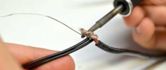
Soldering loose wires
Now we will do practice. Let's say we have an LED and a resistor. You need to solder a cable to them. In this case, mounting plates, pins and other auxiliary elements are not used. To achieve this goal, you need to perform the following operations:
- Remove the insulation from the ends of the wire. They must be clean as they have been protected from moisture and oxygen.
- We twist the individual wires of the core. This prevents their subsequent fraying.
- We tin the ends of the wires. During this process, it is necessary to bring the heated tip to the wire along with solder (which should be evenly distributed over the surface).
- We shorten the leads of the resistor and LED. Then you need to tin them (regardless of whether the parts are old or new).
- Hold the leads parallel and apply a small amount of solder. As soon as the gaps are evenly filled, you need to quickly remove the soldering iron. Until the solder hardens completely, there is no need to touch the part. If this does happen, then microcracks appear, which negatively affect the mechanical and electrical properties of the connection.
Soldering printed circuit boards
In this case, it is necessary to apply less effort than in the previous one, since here the board holes play a good role as a retainer for parts. But experience is important here too. Often the result of the work of beginners is that the circuit begins to look like one large and continuous conductor. But this is not a difficult task, so after a little training the result will be at a decent level.
Now let's figure out how SMD installation occurs in this case. Initially, the soldering iron tip and solder are simultaneously brought to the soldering site. Moreover, both the processed pins and the board must heat up. It is necessary to hold the tip until the solder evenly covers the entire contact area. Then it can be drawn in a semicircle around the treated area. In this case, the solder must move in the opposite direction.
We ensure that it is evenly distributed over the entire contact area. After this, remove the solder. And the last step is to quickly remove the tip from the soldering site. We wait until the solder takes its final shape and hardens. This is how SMD installation is carried out in this case.
The printed circuit board at the first attempts will not look so great, but over time you can learn to make it at such a level that you cannot distinguish it from the factory version.
Source: https://FB.ru/article/251041/smd-montaj-osnovyi-payki-payka-pechatnyih-plat-i-tehnologiya-montaj-smd-domashnih-usloviyah
Soldering temperature of SMD components
This article will cover a short guide on soldering SMD components .
You will learn how to solder multi-legged microcircuits, as well as get acquainted with the main points and possible difficulties that may arise during the soldering process and learn how to avoid them.
The article clearly shows how to solder SMD components with your own hands , and also talks about the necessary equipment and solders, I hope it will be useful!
Every day, radio amateurs are increasingly using SMD parts and components in their work. Despite their size, they are easier to work with: you don’t need to drill holes in the board, bite off long pins, etc. It is imperative to master soldering of SMD components, as it will definitely come in handy.
This master class is not intended for beginners in soldering, but rather for amateurs who are good at soldering but have a little difficulty soldering multi-legged microcircuits or controllers.
What you need to solder SMD components
It’s best to buy a ready-made kit for soldering SMD components , which contains all the necessary tools and accessories.
Buy SMD soldering kit
This is a minimal set, without expensive soldering stations, hair dryers and desoldering pumps.
We solder SMD components with our own hands
So, let's start with the most difficult thing - soldering the controller in the QFP100 case. With chip resistors and capacitors, I think everything is clear. The main rule here: there is no such thing as too much flux, or you won’t ruin the soldering with flux.
Excessive application of flux prevents tin from spreading abundantly over the contacts and shorting them. There is also a second minor rule: even a little solder can be a lot.
In general, you need to dose and apply it to the sting very carefully so as not to overdo it, otherwise it will flood everything at once.
Soldering SMD contacts of the microcircuit
Here you can already use both liquid and viscous flux. We apply it very liberally to the contacts.
We wet the tip with a drop of solder and clean off the excess with a sponge.
And, carefully move along the lubricated contacts.
There is no need to rush in this matter.
Watch the video with the master class:
Be sure to watch the video, where you can clearly see the movement of the soldering iron and all the manipulations.
Source: https://steelfactoryrus.com/temperatura-payki-smd-komponentov/
How to properly harden and swim: instructions for beginners
In order not to get sick in winter, to become physically resilient and to have a cheerful spirit, you need to harden yourself. This process is gradual and requires compliance with basic rules. And after hardening, you can take up winter swimming and dive into an ice hole in the coldest weather.
Hardening brings great benefits. Its mechanism of action is based on irritation of receptors, located in large numbers on the skin, and affecting the entire body. The procedure increases the tone of the dermis and cardiovascular system, reduces arrhythmia. Strengthens the nervous system and gives a boost of energy for the whole day.
Accelerates metabolic processes in the body and promotes weight loss. Hardening activities lead to strengthening of the immune system and improve resistance to viral diseases. The thermoregulation system, whose work is based on maintaining a constant body temperature relative to external environmental conditions, copes faster and better.
But hardening must be done correctly.
Contraindications for hardening and winter swimming
Hardening is a stressful situation for the body. And this procedure is not suitable for everyone. Instead of a positive effect, when the body is strengthened and rejuvenated, irreparable harm is caused. There is an exacerbation of chronic diseases, a cold appears, which can turn into inflammation of the respiratory system.
Subscribe to our INSTAGRAM account!
There are a number of contraindications for those who should not engage in hardening:
- autoimmune diseases such as vasculitis, lupus erythematosus and others;
- diseases of the genitourinary system and respiratory organs;
- diseases of the cardiovascular system - coronary heart disease, obliterating diseases of the peripheral arteries and heart failure.
Elderly people should approach the procedures with caution. A sharp temperature contrast leads to heart attacks, strokes, and the development of diseases of the nervous or cardiovascular systems.
There is always an alternative to hardening - sports with moderate loads. After all, the main goal is to strengthen the body, and not to harm yourself.
If the body does not tolerate cold well
Hardening with cold water gradually develops the habit of not reacting sharply to cold. However, there are people who have a very difficult and slow time adapting to low temperatures.
This depends on several factors:
- A small layer of fat. The natural protective barrier does not stop the cold. It affects the internal organs and causes severe chills. If there is anemia and hypothyroidism, when the thyroid gland is not active enough.
- Raynaud's phenomenon. It leads to vasospasm in the extremities.
Many diseases are treatable. It is necessary to eliminate the cause so that it does not feel bad after dousing with cold water. Only a healthy body will benefit from hardening and give a good mood.
How to temper yourself correctly
It is important to follow the basic recommendations for dousing with cold water so as not to harm your health and strengthen the body.
Rule No. 1: Start hardening only when the body is healthy
If you have chronic diseases in remission or the body has not fully recovered from a cold or viral disease, you should first wait for a complete recovery and only then begin hardening procedures.
Follow Econet on Pinterest!
Examine the body.
A contraindication to cold dousing is the presence of serious damage to the skin. These include purulent inflammation. Exposure to ice water will cause an even larger abscess. People who suffer from high eye pressure experience vasospasm after exposure to cold. This leads to serious complications, including retinal detachment.
For those suffering from high or low blood pressure, you should be careful not to provoke a crisis.
It is advisable to undergo an examination by a doctor before starting hardening and get his recommendations.
Rule #2: Temper up gradually to avoid stress
Not everyone is accustomed to endure being doused with cold water steadfastly and with pleasure. It is important to have a positive attitude towards getting healthy from the very beginning. To maintain a positive mood, start small - with your morning wash.
If you are in the habit of using water at room temperature, then lower it by one degree every day. This will not lead to stress, will give you vigor and motivate you for further more extensive hardening.
Rule No. 3: Maintain regularity and do not take breaks
Hardening is a system. It starts with something small: washing, wiping with a cold towel or dousing your feet. Everyone decides for themselves which method to choose. Gradually the body gets used to the cold. This process must not be disrupted. Once we started, we need to continue.
Subscribe to our Yandex Zen channel!
Long trips, outdoor recreation or other changes in location should not become an obstacle to the hardening process. If there is a break, you will have to start again.
Winter swimming rules
Winter swimming is a quick dive into icy water or a short swim over a short distance. The body instantly loses heat and not everyone can withstand such an event. They prepare for it thoroughly.
After long-term and daily procedures of small exposure to cold water on the body, it is prepared for even greater cold loads.
To switch to winter swimming:
Start taking a shower. First, cool water - 36°C. Lower the temperature by 1°C every day. After dousing, move actively to increase blood circulation. Rub your body with a dry and warm towel to warm up.
Stay warm. Drink hot tea and warm your feet. Avoid alcoholic drinks.
Go out into the frosty air every day, lightly dressed. Walk for 2-3 minutes at first. Gradually increase the duration to accustom your body to the cold.
The best publications in the Econet.ru Telegram channel. Subscribe!
When you feel ready to dive into the hole, follow the rules:
- Warm up well with physical exercises before swimming. Wear shoes when going to the dive site so as not to get hypothermic and not get injured on the ice. Don't dive in head first. It contains cold-sensitive vessels. Spasm and serious health consequences are possible. Only experienced walruses allow themselves to dive headlong.
- After swimming, be sure to dry yourself with a warm towel and do active exercises.
- Then rub your body. The direction of movement is from the limbs to the body. Massage your lower back, stomach and chest clockwise.
- Active actions after diving make the blood circulate faster and the blood vessels dilate.
Good health, vigor and high spirits indicate that the preparation for winter swimming went well. Continue diving into the ice hole, but no more than 3 times a week. Exposure to low temperatures causes stress in the body and requires 1 to 3 days to restore resources.
If the chill from the cold does not go away after diving, then the body needs additional time to get used to the ice water.
It is worth resuming dousing with cold water and holding off on swimming in the ice hole. During the coldest months of winter, take a break to avoid hypothermia and illness. An alternative to diving is running for several kilometers and active sports. Published by econet.ru
*Ekonet.ru articles are intended for informational and educational purposes only and do not replace professional medical advice, diagnosis or treatment. Always consult your physician with any questions you may have about a medical condition.
Subscribe to our channel!
Source: https://econet.ru/articles/kak-pravilno-zakalyatsya-i-morzhevat-instruktsiya-dlya-novichkov
Soldering technologies for SMD components and their implementation at home
Over the past few years, surface mount radio technology has become very popular and is used in the production of most modern electronic devices.
The abbreviation SMD stands for surface mounted device, which in turn can be translated as “surface mounted device”.
Actually, the very name of this technology fully reveals its essence - radio components are mounted directly on the surface of the board, but unlike wall-mounted components, SMD components do not require special holes for mounting.
The absence of special holes for installing radio components made it possible to make printed circuit boards more compact. The use of surface mount technology can significantly save space on the board, which in turn allows you to increase the density of radio components and make more complex devices.
In addition, most SMD components are miniature in size, due to the fact that they do not require large pins like lead components. But many people mistakenly believe that all SMD components, without exception, are very small. Among them, quite often there are large radio components that differ from their “lead” counterparts only in the type of conclusions (which is logical).
But let's move on to the essence of the article, namely the question of how soldering of SMD components is carried out and whether it can be done at home.
You might be interested in this:
Source: http://meandr.org/archives/26111
Hand soldering of miniature SMD elements | Homemade catalog
Surface-mount components, as their name suggests, involve mounting onto the surface of the board rather than into holes like older components. SMDs (surface mount elements) are lighter, cheaper, smaller, and can be placed closer together. These factors, as well as others, have contributed to the widespread use of leadless components today.
There are many relatively inexpensive tools and simple methods for soldering and desoldering SMDs.
SMD Soldering Tools
- Temperature-adjustable soldering iron. A 10 bucks tool with no temperature control is not really the best tool to learn how to solder SMT. You don't need an expensive soldering station, but you do need to be able to control the temperature.
A relatively inexpensive $50 adjustable soldering iron has a temperature control knob from 0 to 5.
It comes with the familiar ST3 wedge-shaped tip, which may be too wide for chip components, but it is still quite commonly used for soldering. Many people will feel more comfortable working with ST7 or ST8 tapered blades. Miniwave nozzle ST5 is convenient for soldering parts in QFP, QFN, PLCC, SOIC packages.
A small depression in its cut surface allows you to hold solder in an amount sufficient for distribution over the entire row of pins of the microcircuit.
- Solder. For hand soldering of surface mount components, we need 60/40 tin-lead alloy in the form of a wire with a diameter of 0.015 inches (0.4 mm). There may be more lead in the alloy and thicker wire may be needed if you need to secure the connector to the board.
- Soldering tape. This is one of the things that is simply indispensable for hand soldering. Also known as a solder scraper - helps remove solder. It is woven from thin copper wires into a long braid, and sometimes has flux inside.
- Tweezers. Flat-tip grippers are essential for moving and holding miniature chip components. These ones with curved ends are very convenient. You can get these for about $5.
Some people use vacuum tweezers to pick up and replace small components.
- Flux. It's not always used when manually soldering SMD boards, but some people can't do without it. Flux can be used even with ready-made solder wires, since the thinner the wire, the less solvent it contains. During soldering, the element legs heat up more than once, so it is important to add a little external flux.
- Magnifying glass with flashlight. In any case, you will need a lot of light and a magnifying glass when soldering miniature elements. There are good head lenses like OptiVisors, which magnify 2.5 times, and have built-in lighting lamps.
To check your work you will need a magnifying glass with 10x magnification. These magnifiers are also available with a built-in flashlight.
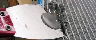
Tape desoldering technique
To make the desoldering, place a copper pigtail on the legs of the element and run a hot soldering iron over it. The heat and flux will draw the tin onto it. Use the other end of the braid if nothing seems to be working (a small piece of it is cut off from the spool).
Depending on the circumstances, the pigtail needs to be raised higher, and the heat will be removed along it upward from the area where the soldering iron touches.
To clean the braid, you need to add more flux.
Soldering two-pin elements
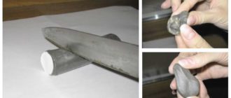
Components such as resistors and capacitors often crack due to uneven heating. Solder their two opposite ends at the same time. Use tweezers to hold the part on the board. Apply a little solder to one side to create a neat fillet between the end of the element and the pad. Ideally, you should end up with a smooth bridge, and not a huge ball of tin at the end.
If not, use copper braid to remove excess solder.
Soldering SOIC and other multi-pin ICs
Use tweezers or a suction cup to hold the SOIC (Small Output Integrated Circuit) on the board. Solder one of the pins of the microcircuit, preferably it is the power pin. Then grab the other power terminal on the opposite side. Make sure all the other legs line up above their pads.
Connect the remaining legs - starting with the outermost, unsoldered contacts, apply a wave of solder, feeding tin wire to the soldering iron tip if necessary. Do this operation as quickly as possible without allowing the chip to overheat.
Removing sagging
When you are finished soldering, inspect the legs of the chip elements. Small bridges between them can be easily removed by quickly heating them with a soldering iron dipped in flux. Thick jumpers are removed in a familiar way - using soldering tape.
Source: https://volt-index.ru/electronika-dlya-nachinayushih/ruchnaya-payka-miniatyurnyih-elementov-smd.html