Soldering SMD components at home
Many people wonder how to properly solder SMD components. But before we deal with this problem, it is necessary to clarify what these elements are. Surface Mounted Devices - translated from English, this expression means surface-mounted components.
Their main advantage is their greater mounting density than conventional parts. This aspect affects the use of SMD elements in the mass production of printed circuit boards, as well as their cost-effectiveness and manufacturability of installation.
Conventional parts with wire-type leads have lost their widespread use along with the rapidly growing popularity of SMD components.
Errors and basic principles of soldering
Some craftsmen claim that soldering such elements with your own hands is very difficult and quite inconvenient. In fact, similar work with VT components is much more difficult. In general, these two types of parts are used in various fields of electronics. However, many people make certain mistakes when soldering SMD components at home.
SMD components
The main problem that hobbyists face is choosing a thin tip for a soldering iron. This is due to the existence of an opinion that when soldering with a regular soldering iron, you can stain the legs of SMD contacts with tin.
As a result, the soldering process is long and painful. Such a judgment cannot be considered correct, since in these processes the capillary effect, surface tension, and wetting force play a significant role.
Ignoring these extra tricks makes it difficult to do the DIY job.
Soldering SMD components
To properly solder SMD components, you must follow certain steps. To begin, apply the soldering iron tip to the legs of the taken element.
As a result, the temperature begins to rise and the tin begins to melt, which eventually completely flows around the leg of this component. This process is called wetting force. At the same instant, tin flows under the leg, which is explained by the capillary effect.
Along with wetting the leg, a similar action occurs on the board itself. The result is a uniformly filled bundle of boards with legs.
Contact of the solder with adjacent legs does not occur due to the fact that the tension force begins to act, forming individual drops of tin. It is obvious that the described processes occur on their own, with only a small participation of the soldering iron, who only heats the legs of the part with a soldering iron. When working with very small elements, they may stick to the soldering iron tip. To prevent this from happening, both sides are soldered separately.
Factory soldering
This process occurs on the basis of a group method. Soldering of SMD components is carried out using a special solder paste, which is evenly distributed in a thin layer onto the prepared printed circuit board, where there are already contact pads.
This application method is called silk-screen printing. The material used is similar in appearance and consistency to toothpaste. This powder consists of solder to which flux has been added and mixed.
The deposition process is performed automatically as the printed circuit board passes through the conveyor.
Factory soldering of SMD parts
Next, robots installed along the motion belt arrange all the necessary elements in the required order. As the board moves, the parts are firmly held in place due to the sufficient stickiness of the solder paste.
The next step is to heat the structure in a special furnace to a temperature slightly higher than the one at which the solder melts. As a result of such heating, the solder melts and flows around the legs of the components, and the flux evaporates.
This process makes the parts soldered into their seats. After the oven, the board is allowed to cool, and everything is ready.
Required materials and tools
In order to do the work of soldering SMD components with your own hands, you will need to have certain tools and consumables, which include the following:
- soldering iron for soldering SMD contacts;
- tweezers and side cutters;
- an awl or needle with a sharp end;
- solder;
- a magnifying glass or magnifying glass, which is necessary when working with very small parts;
- neutral liquid no-clean flux;
- a syringe with which you can apply flux;
- in the absence of the latter material, you can get by with an alcohol solution of rosin;
- To make soldering easier, craftsmen use a special soldering hair dryer.
Tweezers for installing and removing SMD components
The use of flux is absolutely necessary, and it must be liquid. In this state, this material degreases the working surface and also removes the formed oxides on the metal being soldered.
As a result, an optimal wetting force appears on the solder, and the soldering drop better retains its shape, which facilitates the entire work process and eliminates the formation of “snot.”
Using an alcohol solution of rosin will not allow you to achieve a significant result, and the resulting white coating is unlikely to be removed.
Solder for soldering
The choice of soldering iron is very important. The best tool is one that allows you to adjust the temperature.
This allows you not to worry about the possibility of damage to parts due to overheating, but this nuance does not apply to moments when you need to desolder SMD components.
Any soldered part can withstand temperatures of about 250–300 ° C, which is ensured by an adjustable soldering iron. If such a device is not available, you can use a similar tool with a power of 20 to 30 W, designed for a voltage of 12–36 V.
Using a 220 V soldering iron will not lead to the best consequences. This is due to the high heating temperature of its tip, under the influence of which the liquid flux quickly evaporates and does not allow the parts to be effectively wetted with solder.
Experts do not recommend using a soldering iron with a conical tip, since it is difficult to apply solder to parts and a lot of time is wasted. The most effective is the sting called “Microwave”. Its obvious advantage is a small hole on the cut for more convenient capture of solder in the right amount. With such a tip on the soldering iron it is convenient to collect excess solder.
Soldering iron tip “Microwave”
You can use any solder, but it is better to use a thin wire, with which you can conveniently dose the amount of material used. The part to be soldered using such a wire will be better processed due to more convenient access to it.
Work order
The soldering process, with a careful approach to theory and gaining some experience, is not difficult. So, the whole procedure can be divided into several points:
- It is necessary to place SMD components on special pads located on the board.
- Liquid flux is applied to the legs of the part and the component is heated using a soldering iron tip.
- Under the influence of temperature, the contact pads and the legs of the part themselves flood.
- After pouring, remove the soldering iron and allow time for the component to cool. When the solder has cooled, the job is done.
Soldering process for SMD components
When performing similar actions with a microcircuit, the soldering process is slightly different from the above. The technology will look like this:
- The legs of the SMD components are installed exactly at their contact points.
- In areas of contact pads, wetting is performed with flux.
- To accurately place the part in the seat, you must first solder one of its outer legs, after which the component can be easily aligned.
- Further soldering is carried out with the utmost care, and solder is applied to all legs. Excess solder is removed with a soldering iron tip.
Soldering iron with a sharp tip 24 V.
How to solder with a hair dryer?
With this soldering method, it is necessary to lubricate the seats with a special paste. Then the required part is placed on the contact pad - in addition to components, these can be resistors, transistors, capacitors, etc. For convenience, you can use tweezers.
After this, the part is heated with hot air supplied from a hair dryer, at a temperature of about 250º C. As in previous examples of soldering, the flux evaporates under the influence of temperature and the solder melts, thereby flooding the contact tracks and legs of the parts. Then the hair dryer is removed and the board begins to cool.
When it has cooled completely, soldering can be considered complete.
Hair dryer for soldering small parts
Source: https://LampaGid.ru/elektrika/komponenty/pajka-smd
How to solder (change) surface mount BGA chips?
page » How to solder (change) surface mount BGA chips?
Almost all modern electronics, including tablets, laptops, smartphones, etc., contain surface-mount chips on their motherboards. The design of such microcircuits differs in that instead of the classic wire leads, it contains a ball array.
That is, a certain number of metal contact points, which in fact represent pieces of solder in the form of small balls. Such balls, accordingly, cannot be inserted into traditional holes on the board, but BGA chips can be soldered to mounting pads. This is surface mounting.
Let's look at how to solder BGA chips, as well as the necessary equipment for the job.
Replacing surface mount chips
It would seem that surface mount integrated circuit technology requires a unique mechanical approach. Looking at such a chip installed on the motherboard of a laptop or other equipment, it is difficult to imagine how, for example, you can replace a chip at home if it fails. However, as practice shows, home repairs with BGA (Ball Grid Array) replacement are quite possible.
EVERYTHING FOR BGA
How to solder a microcircuit constructed using BGA technology - a chip that is simply applied to the surface of a printed circuit board? It turns out it's not difficult at all
Of course, you need to have some skills in repairing electronic equipment and soldering skills in microcircuits, in particular. You will also need a certain instrumental and material base:
- electric soldering gun,
- auxiliary infrared heater,
- miniature vacuum pump with suction cup,
- special flux,
- electric soldering iron,
- other auxiliary tool.
In addition to the entire designated material base, an important component in the soldering of surface-mount BGA microcircuits is a special flux - a paste-like substance.
What is flux for soldering BGA chips?
In fact, soldering flux for surface-mount microcircuits is a chemical (acidic) compound, thanks to which high-quality “cleaning” of soldering areas is achieved. There are two types of paste-like (gel-like) fluxes:
- Fluxes requiring subsequent cleaning.
- Fluxes that do not require cleaning.
Meanwhile, in any case, you should still resort to cleaning the board from flux residues after completing all work, thereby preventing possible destruction of the PCB structure in the future. It should be noted: almost all fluxes intended for soldering surface-mount microcircuits (BGA) can be washed quite easily.
BGA PASTE
Flux, a substance used when soldering surface-mount chips, looks like this consistency.
Typically packaged in plastic syringes for ease of use
The commercial market offers a wide selection of materials of this kind for working with surface-mount microcircuits.
In particular, a rich assortment is presented on the well-known Chinese portal Aliexpress. Moreover, the prices of Chinese goods are significantly lower than branded European ones, and the quality is quite consistent.
If desired, it is possible to make flux yourself using a certain set of substances:
- glycerin (a mixture of glycerin and aspirin),
- acetic acid (ammonia),
- alcohol solution of rosin,
- wax.
However, it is preferable to use a ready-made commercial product.
Infrared motherboard heater
Additional heaters, for example, an infrared desktop device with automatic temperature setting, are used to warm up the motherboard from the bottom side relative to the installation of the BGA chip.
In this way, uniform heating is achieved during the process of soldering (replacing) a surface-mounted BGA microcircuit, and deformation of the motherboard PCB structure is eliminated.
HEATER
The Chinese portal Aliexpress is full of such ceramic panels of infrared radiation, which are proposed to be used under the tool for lower heating of electronic boards
However, digital infrared heaters are quite expensive (from 5,000 rubles), so for home use (individual, not large-scale repairs) it is more logical to use simple ceramic infrared plates for soldering BGA microcircuits.
An upper heating tool is used together with bottom heating. In particular, the traditional tool here is a soldering iron - a modern-style electric soldering iron, “sharpened” for soldering (desoldering) miniature elements of electronic boards.
Electric soldering gun for surface mount chips
This type of soldering tool differs from a traditional soldering iron with a metal tip in that in this case a working tip is not used. Instead of a working tip, the required temperature background in the soldering areas is provided by a flow of heated air. Accordingly, the design of a soldering gun should be considered a kind of air pump, equipped with a heating and control system.
BGA SOLDERING IRON
One of the many design options for a soldering station that supports the use of a conventional soldering iron with a tip and the operation of a soldering gun
There are soldering guns of various designs and operating capacities.
Factory-made structures usually have functions for controlling the strength of the air flow, the temperature of the outgoing air, and allow visual monitoring of parameters.
At the same time, it is possible to make a completely tolerable soldering iron from an ordinary electric soldering iron by performing some modernization of the design.
Vacuum pump with suction cup for BGA chips
This rather original tool is desirable for use when it comes to soldering (desoldering) surface mount BGA type microcircuits. In fact, to work with other electronic components of modern technology, a vacuum suction cup may also be required quite often.
Typically, soldering stations of industrial (commercial) production are already equipped with this functionality. The good thing about this tool is that it allows you to carefully dismantle a BGA chip that has been heated to the point of dismantling, without affecting nearby components. However, let's get down to business - how to unsolder and replace a faulty BGA chip on the motherboard.
Do-it-yourself BGA chip replacement at home
So, the home technician has at his disposal a laptop motherboard, where during the diagnostic process a faulty surface-mount BGA chip was discovered, in particular, a chip from one of the bridges of the computer board. It is necessary to dismantle the BGA surface-mount chip, and instead of the dismantled chip, it is necessary to install another - serviceable component.
STENCIL
The process of replacing a faulty surface mount chip on a laptop motherboard. You will need information on removing the board from the device body.
First, the motherboard is removed from the laptop case, for which you should refer to the service instructions of the specific tablet computer manufacturer. In each individual case, the procedure for dismantling the motherboard may differ radically.
Preparing the motherboard for repair
The removed laptop circuit board is installed above the infrared quartz heater in such a way that the maximum heat flow falls on the area where the chip is being soldered.
The next step is to treat the surface-mount chip with a special flux. The dismantled chip, usually rectangular (square) in shape, is processed by uniformly applying a small amount of gel-like flux around the perimeter.
FLUXES
Treatment of the dismantled BGA chip with a special flux - coating the four sides of the chip body with a gel-like substance using a plastic syringe
Further according to the technological procedure:
- turn on the infrared bottom heater,
- wait for the applied flux to melt,
- at a temperature of 250-300ºC, remove the corner plastic clamps of the chip,
- After reaching a temperature of 300-325ºC, use a soldering iron.
Top heating of the microcircuit with a soldering hair dryer
A soldering gun is used to heat a surface-mounted BGA chip along the top side of the chip. If a soldering station with a temperature controller is used, the parameters are usually set to the range of 350-400ºC. Evenly directing the air flow of the hair dryer to the area of the microcircuit, wait for the tin to completely melt.
The moment of complete melting can be determined by periodically checking the condition of the chip. Once the chip begins to “wiggle” in place, it’s time to use the suction cup tool.
Using a suction cup tool, they cling to the center of the microcircuit body and simply remove the chip from its installation site. When the tin is completely melted, this operation does not cause any difficulties.
Preparing the landing area of the microcircuit on the board
After removing the faulty surface mount IC (BGA), you should prepare the installation site. Preparation consists of “cleaning” the contact pads for the tin “balls” of the new microcircuit. For this procedure, it is enough to use a regular soldering iron with a tip that is well sharpened and has smooth working edges.
BALLOONS
The procedure for stripping a surface mount chip (BGA) using a conventional soldering iron. The process takes no more than one or two minutes
The “stripping” area is first treated with a small amount of flux for BGA soldering and then the remaining tin is carefully removed with a soldering iron tip.
Radio amateurs use different methods for cleaning, including the option when using a cable braid. But the practice of an established radio amateur shows that one soldering iron, patience and accuracy are quite enough.
Installing and soldering a new serviceable component
At the next stage, the BGA chip prepared for replacement should be placed in place of the dismantled chip. In this case, it is necessary to correspond to the markers (lines) on the electronic board, including the “key” marker, which indicates the correct position of the chip according to the working contacts.
Next, the infrared quartz bottom heating heater is turned on, and the board is heated until the flux melts. Turn on the soldering gun and heat the upper area of the surface-mount microcircuit to a temperature of 350-400ºC.
That's all. A new BGA type microcircuit is installed to replace the faulty one. The laptop motherboard is ready for use. More details in the video below.
Master class on desoldering (soldering) BGA chips
A video demonstration of the process of removing a faulty chip and then installing a working BGA chip as a replacement. Repairing a laptop motherboard at home with all the details:
The final touch on soldering BGA chips
As the text above shows, the procedure for replacing (resoldering) surface-mount microcircuits on various electronic boards is a completely solvable task. Moreover, this work can be done at home, provided you have the appropriate tools. Having the skills to replace BGA chips opens up wide opportunities for organizing your own business repairing household electronic appliances.
Source: https://zetsila.ru/%D0%BA%D0%B0%D0%BA-%D0%BF%D0%B0%D1%8F%D1%82%D1%8C-%D0%BC%D0 %B8%D0%BA%D1%80%D0%BE%D1%81%D1%85%D0%B5%D0%BC%D1%8B-bga/
Rules for using a soldering gun
Instrument electronics is developing simultaneously with general electronics, which results in the continuous improvement of the tools used during repairs.
One of these tools was a soldering gun. Many modern household appliances, such as TVs, tablets, laptops, can only be repaired with its help.
What is needed for work
A soldering gun, also called a hot-air soldering station, is a multi-component tool with a large number of functions for repairing modern devices. It allows you to solder SMD components, capacitors, LEDs and other parts. The same applies to BGA-type chips, which make installation more dense. Today, almost every electronic component in modern devices is made in this way.
To solder SMD components, you need the following materials and devices:
- actually, the hair dryer itself;
- attachments for it;
- flux with solder paste;
- copper braid;
- some kind of device for prying up parts (tweezers, for example);
- medium-soft brush;
- lens;
- a soldering iron with a thinner tip compared to a standard one;
- stencil for “rolling”.
To work competently with a soldering gun means to be careful, have angelic patience, and be extremely careful.
Sequence of actions using the example of an SMD component
Let’s say that on the working printing surface of the electronic unit being repaired there is a burnt-out SMD box that needs to be dismantled. To remove it and install a new one, you need to select a compact nozzle for the hair dryer and prepare flux.
The temperature regime on the soldering hair dryer is set within 345-350 degrees using a regulator. Then they apply flux to the part to be replaced, and begin to slowly “warm up”.
The air pressure during the process should not be too strong, otherwise there is a risk of blowing away nearby elements. The culprit of the breakdown continues to be heated until the solder begins to melt, which will be immediately noticeable.
It may take about three minutes to warm up, and this is normal, there is no need to rush. If the solder persists for a long time, you need to add 5 degrees.
After the solder has liquefied, carefully dismantle the SMD part. During the process, it is important not to knock down the neighboring components, since they have probably lost stability due to the melting of the solder holding them in place.
Upon completion of the operation, the copper braid must be used to clean the “spots” (contact pads), then provide small bumps in the same places with solder paste or solder.
A serviceable smd is placed in the old place with a minimum amount of flux. Heat the part with a soldering hair dryer until the solder shines brightly, spreading over each of the contacts.
Features of working with BGA chips
When soldering BGA type microcircuits, the same temperature range is selected from 345 to 350 degrees, ensuring moderate air pressure to prevent blowing off the “neighbors”. During operation, the soldering gun should be held at an angle of 90 degrees with respect to the board. To avoid failure of the chip, you should not heat it only in the center; it is better to go around the mounting element around the perimeter.
After 1-3 minutes have elapsed, you can try to slightly lift the chip above the board using tweezers. If the chip does not budge, the solder is still hard. To avoid damage to the conductive paths of the board, you need to use the regulator on the hair dryer to “throw on top” 5 degrees of temperature and continue heating.
Heating from below
This technique is not only useful when working with a soldering gun, but also increases the convenience of soldering.
The board is secured with a clamp, the temperature is set to 200 degrees and warmed up for five minutes, after which they begin to work as usual.
Using thermal tape, you can shield nearby elements.
After removing the chip, the contacts are cleaned with the above braid. Do the same with the board.
All procedures must be carried out carefully to prevent damage to the circuit. If you don't have copper braid on hand, you can remove the solder using a soldering iron with a thin tip.
Reballing procedure
To carry out reballing, the chip is placed in a stencil and secured with specialized electrical tape. Apply solder paste on the back side with a finger or spatula, then set the hair dryer to a temperature of about 300 degrees and begin to warm it up. After the characteristic shine from the molten solder paste appears, allow the solder to cool completely.
To free the stencil from the chip, remove the electrical tape and heat the stencil to approximately 150 degrees; at the end of the procedure, the part should be free. It happens that it is impossible to immediately remove a part from a Chinese stencil, so it may be necessary to carefully hook it.
During reverse soldering of the microcircuits, the risks are assessed and the chip is laid out the required number of times to ensure an exact match of the heels and balls. Then they set the temperature on a soldering hair dryer to 330 to 350 degrees and heat until the melted solder allows the chip to fall into place on its own.
Source: https://svaring.com/soldering/praktika/pajka-s-fenom
How to solder LEDs correctly: what is important to know, common mistakes
› Workshop
30.08.2019
Today, LEDs are recognized by ordinary users, radio amateurs and industrial enterprises as the most environmentally friendly, compact and energy-efficient light sources.
Low-power diodes are used to backlight monitors, mobile phones and in various toys, and high-power LEDs are used in workshop spotlights and festive luminescence of buildings, in the advertising business.
But the unusual light source has a number of maintenance features, in contrast to energy-saving analogues (ESL) and incandescent lamps. It is not so easy, for example, to solder LEDs. This article is devoted to this issue.
Structure of diode elements
The main difference from other lamps is that LEDs have a positive and negative contact (anode and cathode). When soldering a diode in a circuit, it is important to take this into account.
You also need to understand that there are DIP and SMD LEDs.
The positive contact in DIP is determined quite simply. It is worth taking a close look inside the flask. The positive terminal - the anode - is smaller than the negative one. In the picture, the plus is on the left.
There is a second way - look at the length of the leg. It is longer at the positive terminal.
The third way is with a multimeter. The black terminal of the device is negative, the red terminal is positive. Let's call:
The last method is suitable for both types.
This is perhaps the most important thing to know about the structure of an LED. If you are interested in the theory, we recommend watching the video:
Soldering Features
There are usually no difficulties in soldering DIP type LEDs. Knowing the simple rules of soldering, it’s difficult to make a mistake:
Soldering LEDs is, in principle, not difficult. Small problems regarding how to properly solder a diode appear when working with the SMD type. The fact is that these diodes do not have current-carrying legs; instead, they have contact pads. And, as a rule, SMDs are soldered into boards or tapes.
How to desolder a microcircuit from a board with a soldering iron?
Hi all! The author of the blog popayaem.ru, Vladimir Vasiliev, is in touch with you. Today we will talk about various methods of dismantling microcircuits. It is with them that difficulties arise when soldering into parts of various equipment.
“Why is it needed, you can buy it anyway, it costs a penny!” the average person will exclaim, not understanding and not attaching importance to the wealth hidden in old electronic equipment. I once wrote an article about how I got hold of radio parts when I had nowhere to buy them or nothing to buy them with.
Usually, there are no problems when soldering various small things. This is not a tricky thing, I heated it from the mounting side and pulled the leads out of the mounting holes one by one. The situation is much more complicated with microcircuits; there is more than one output; while one output has warmed up, the other has already cooled down. Moreover, bending the legs one at a time is not the case; that’s the only way they will fall off.
There are several methods for dismantling microcircuits:
Dismantling the microcircuit with a soldering iron
This is the most homeless and hemorrhagic trick when you have nothing but a soldering iron but need to desolder the microcircuit.
In order for this matter to go more or less smoothly, we clean the soldering iron from adhering solder. You can clean it with a special cellulose sponge or just with a damp cloth. Then, using a brush, coat all soldering joints with liquid flux; for this I use alcohol rosin.
Now we first stick the cleaned soldering iron tip into the rosin and then poke it into the soldering points of the microcircuit pins. As a result, slowly, bit by bit, the solder begins to transfer from the mounting pad to the soldering iron tip.
We, as it were, tin the soldering iron tip, but only take the solder from the terminals of the desired microcircuit.
So you need to do a large number of iterations, not forgetting to clean the soldering iron tip each time, until the microcircuit is released from the mounting captivity. It is very important here not to get carried away and not overheat the microcircuit. Also, mounting nickels and tracks can fly off due to overheating, but this is important in the sense that you don’t really need the microcircuit itself, but you do need the board itself.
Removing the chip using a razor blade
The main problem with desoldering microcircuits is, as I already said, that while you are heating one terminal, the other has already cooled down, and in order to remove the microcircuit, all terminals must remain heated at the same time. It’s difficult to do this with a soldering iron, but it’s possible.
You can, of course, barbarically bend the tip of some EPSN soldering iron and use a kind of L-shaped hook to heat up the soldering. Or you can go simpler.
Only in this case you need to use some kind of metal plate or bracket that is not tinned.
A razor blade can be used as such a plate. The blade is needed so that the heat from the soldering iron is concentrated not on one terminal, but is transferred to several at once. The only thing is that a more powerful soldering iron may be required, since at low power the heat that was enough for one pin may not be enough for a whole bunch of leads.
Therefore, we press the blade against a whole row of legs of the microcircuit and begin to warm up all the solders at the same time. We warm up and at the same time rock the microcircuit, you can slip a knife blade under the belly of the microcircuit, trying to lift the microcircuit from one edge. Thus, having freed one row of legs from the mounting captivity, in the same way, we free the second row.
Using dismantling braid
When dismantling microcircuits with a bare soldering iron, the ability of the soldering iron to attract solder is used. A soldering iron tip that is tinned and coated with flux has good wettability and absorbs solder very well. But how can we make this process more efficient?
You can, of course, choose a soldering iron with a wider tip, then it will be possible to remove a larger amount of solder. But you can go the other way, you can use the braid from a coaxial cable. The antenna wire from the TV will do. We tear off this braid from the cable and generously cover it with flux.
Now, if you press such a pigtail to the solders of the microcircuit and walk over it a little with a soldering iron, you can be convinced of the wonderful dismantling properties of the braid. Due to its porosity and hygroscopicity, it absorbs solder much better than any soldering iron tip, thereby freeing the microcircuit terminals.
Nowadays there are special dismantling braids on sale, so you can leave the TV wire alone.
Dismantling microcircuits using a desoldering pump
What do you think will happen if you combine an enema and soldering? You will get something shown in the figure. This is a tin pump and this construct was described in an old magazine, either “Modeler-Constructor” or “Radio Magazine”, I don’t remember.
Now they can look completely different, they can be like in the picture, they can be a modified syringe. But this does not change their essence: the soldering iron heats up the junction and the enema bulb or syringe draws out all the solder.
In principle, a very effective dismantling method.
Using medical needles
In general, the point is as follows. At the pharmacy we buy a needle thin enough to fit into the mounting hole and thick enough to be placed on the terminal of the soldered microcircuit.
Using a file, we file the tip of the needle to make a simple hollow tube; it will be even better if the hole is flared a little. It turned out to be a good dismantling needle
And it’s very easy to work with her. We put our tube on the output of the microcircuit, and use a soldering iron to heat the junction. Now, while the solder is still in liquid form, we insert a needle into the mounting hole and begin to frantically rotate the needle until the solder hardens. By placing a needle on the pin, we thereby isolated the leg of the microcircuit from the solder. The needle has a special coating that impairs the wettability of the solder, so the solder does not stick to the needle.
Now, by the way, there are special dismantling tubes of various diameters on sale, so honey. You don’t have to buy needles anymore.
Use of alloy rose
To dismantle microcircuits, you can use rose alloy or wood alloy. A distinctive feature is that these alloys have a low melting point, less than 100 degrees.
To dismantle, pour a few granules into the joint. Now our task is to organize a puddle of alloy by distributing it over all the legs of the microcircuit. This allowed the low temperature alloy to mix with the solder alloy, resulting in a lower overall melting point. The thermal conductivity of the alloy is sufficient and a puddle of alloy covers all the legs of the microcircuit and melts everything. As a result, the chip is simply removed from the mounting holes.
Well, somehow that’s all I have for today.
I think that the article will be useful especially for beginners and will save several nerve cells when dismantling the next microcircuit.
Well, friends, don’t forget to subscribe to blog updates, and I wish you a sunny spring mood, good luck and success!
From n/a Vladimir Vasiliev
Source: http://popayaem.ru/kak-vypayat-mikrosxemu-iz-platy-payalnikom.html
How to solder correctly with a soldering iron, how to desolder a microcircuit
For professionals, the title of the article may cause a condescending smile. It would seem, what’s so complicated here? I cleaned the contacts, scooped up some solder with the nose of the soldering iron, and applied it to the connection point. For an experienced radio amateur, this process really does not cause problems. But if everyone (including professionals) knows how to solder correctly with a soldering iron, where do unsoldered boards, short circuits between adjacent contacts, and parts that fail due to overheating come from?
Our material will tell novice craftsmen how to learn to solder using traditional and non-standard methods, and for those who consider themselves professionals, it will help improve their skills.
What is soldering
Without referring to Wikipedia, we will explain in our own words. Soldering is the joining of metal contacts using a conductive melt, followed by its solidification. In this case, unlike welding, none of the parts being connected should melt during the process. Of course, after the conductive melt (solder) has solidified, reliable electrical conductivity of the connection must be ensured. Contact resistance cannot affect the characteristics of the electrical circuit.
General rules for working with a soldering iron (we will consider all these points in detail in the review)
- The connection point must be mechanically cleaned of dirt, protective coating and oxides (if the dimensions and design of the parts and conductors allow). What you can focus on: some metals, in principle, cannot be cleaned of the oxide film, at least in air. Only under a continuous layer of special fluxes (we are talking about aluminum and alloys based on it). The fact is that the “winged metal” oxidizes instantly.
- To degrease the connection point, special cleaners are used: fluxes. They should not have a destructive effect on the metal you are working with. Even if the joint seems perfectly clean, soldering without flux is almost impossible. When the heated soldering iron tip touches, thermal oxidation occurs. Important: metals used in electrical engineering (aluminum, copper, silver, gold) in their pure form have good adhesion. Standard solders seem to stick to the surface, securely fixing after hardening. The layer of oxide film not only prevents “sticking”, it is also a dielectric. And fluxes, when heated, activate their cleaning properties, and not only remove invisible contaminants, but also prevent oxidation. Special fluxes have been developed for various materials. Even acids are used.
- The shape and dimensions of the working tip of the soldering iron tip must correspond to the contacts and soldering conditions. The material does not matter: it can be copper, ceramics, or hard alloys, silver-plated.
- Choice of power - the range of 25–60 W is suitable for soldering printed circuit boards. Too high a temperature can not only overheat the soldering area, some radio components fail when exposed to heat. The other side of the coin: low temperature will be removed from the soldering zone by massive contacts or a thick heat-conducting conductor. You will have to keep the tip in the working area for a long time - hence the overheating of the parts again. For example, when the question arises of how to solder a capacitor, it is important to know exactly the degree. The golden rule of soldering: high temperature and short-term heating. This skill comes only with experience.
- Solder selection. From the point of view of adhesion, all types work well. That is, selecting contacts for a specific metal is not task No. 1. But the melting point should be treated carefully. On the one hand, low-melting compounds make it possible to minimize the thermal effect on parts. On the other hand, this creates two additional problems: Firstly, low-melting solder “unsolders off” just as quickly. If the temperature conditions of the contact connection are not very favorable, there is a possibility of loss of contact during operation. Secondly, you will definitely encounter the fact that the solder is already in a liquid state, and the contacts have not yet warmed up for normal adhesion. As a result, the soldering point again overheats.
Let us repeat, these are only theoretical principles, from which it is not yet clear how to solder with a soldering iron. You will see detailed instructions below.
Selecting a soldering iron
If you are not involved in radio work professionally (most likely this is the case, otherwise you would not have studied this material), you have in your arsenal an ordinary soldering iron in one copy. We are not talking about a soldering station at all, since it is quite expensive (albeit a very convenient kit). But for a novice master this is overkill.
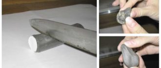
Let's return to soldering irons. The classic is a nichrome heater and a copper tip. In fact, this is the best combination, but for manual control. No temperature control, smooth slow heating. At the same time, the copper tip holds the temperature perfectly, and often compensates for the heat dissipation at the soldering site. Another advantage is that the soft material allows you to mold any tip configuration. You can literally rivet and cut out a tip for a specific type of soldering.
The only drawback is that copper burns out quickly, and this type of tip is actually a consumable item. It constantly has to be sharpened with a file.
Tip: Be sure to use a hammer before shaping the tip with a file. Once the copper rod is sealed, it will last longer. A little lost time is more than compensated for by ease of use.
The illustration shows the classic “screwdriver” shape. A universal tip for most amateur jobs.
If your “heating device” is equipped with a temperature controller, you must take into account the inertness of copper. It dials the set number slowly and also slowly cools down.
The ceramic tip with silver plating is a modern accessory. If the question is how to work with SMD format parts, or how to desolder a chip from a double-sided board, this is your option. However, they are not so convenient for soldering powerful heat-intensive wires and contacts.
Such a soldering iron heats up instantly, and you can precisely control the degrees on it (if there is a regulator).
The heating method can be any. The same ceramic heater as the tip, or nichrome. Induction heaters are also used on copper soldering irons, but these are rather exotic.
How to desolder a microcircuit with a soldering iron
By picking up the microcircuit with a screwdriver and applying slight pressure on it, while simultaneously warming up the legs of the microcircuit located on one side with a soldering iron, you can gradually desolder it. How to do this is shown in more detail in the video at the bottom of the article (watch starting at 15 minutes 15 seconds).
How to solder or desolder a microcircuit without a soldering iron
You already understand that successful soldering requires heating the part to the melting temperature of the solder. It can be melted using a heat gun or soldering hair dryer. This is an analogue of a construction hair dryer, only it is compact and often equipped with special molded nozzles.
With its help, the working area is heated, while the solder melts not at a certain point, but over a relatively large area. This is an effective method, especially if it is necessary to desolder the microcircuit (all legs heat up at the same time). But with this method there is a risk of damaging the part itself from overheating.
If you remove the faulty element, no problem.
In general, a soldering gun should only be used in cases where the traditional soldering method is not possible. For example, when mounting SMD parts (who doesn’t know, they don’t have legs) on a radiator plate.
Flux selection
We will talk about soldering copper parts. There are special acid compositions for iron and aluminum; this is a topic for a separate material.
In fact, it's everyone's personal preference. You just need to try different formulations and determine the best one for yourself. Some people like soldering fat (the consistency is like grease), some like liquid flux. We will talk about traditional rosin.
More precisely, how to solder correctly with it.
This flux is based on pine resins and has excellent cleaning properties. It provides mechanical and chemical cleaning, in addition, it protects the surface well from oxidation when heated. There is only one drawback: in its pure form, rosin is solid. This means that it cannot be applied to the parts to be joined in advance. However, the technology is there:
- Having touched the rosin with the tip of the soldering iron, we collect solder on it;
- we immerse the legs of the part or the wire in the flux using a soldering iron (it melts), while the surface is covered with a thin layer of solder;
- similarly apply solder to the soldering area;
- connect the tinned part (wire) to the soldering point;
- touch the flux with a soldering iron, then pick up solder, dip it in rosin again;
- Immediately transfer the tip to the soldering zone.
Parts have been soldered this way for many decades. With a certain skill, there are no restrictions on the choice of materials for joining. This technique is ideal for training. If you master it, the other methods will seem even easier.
Tip: To clean solder surfaces that have a layer of oxide on them, regular pharmacy aspirin is suitable. It contains acetyl salicylic acid. It must be ground into powder and applied to the contacts.
Soldering with liquid or paste fluxes
The advantage of such compounds is that they can be pre-applied to the connection point. That is, the flux begins to work even before heating. When touched with a soldering iron, the second stage of the reaction occurs, and the liquid flux serves as a lubricant for the spreading of solder.
Another plus is that a paste or liquid cleaner increases the contact patch. The main problem with soldering non-flat objects is that the heat transfer area from the soldering iron is minimal. If the point of contact is moistened with flux, the temperature is transmitted more efficiently.
The only drawback: there is no mechanical impact on the surface.
Information: some old-school professionals dissolve pine rosin with alcohol or a more liquid flux, and an effective composition is obtained with virtually no drawbacks.
What kind of solder to solder
These alloys are made from tin, lead, copper, nickel, or silver. Tin-lead solder (PLS) is used to work with circuit boards and household wiring. Despite the great variety, they can be divided into two types:
- soft (melting point up to 300°C);
- solid (melting point over 300°C).
Any form of release: lump, wire, powder, paste. A universal option is wire up to 2 mm in diameter. It is convenient to put it on the soldering iron tip or insert it directly into the soldering zone.
An interesting offer from manufacturers is solder paste or powder. This is finely dispersed solder, to which liquid flux is added for viscosity. The result is a consistent composition with high adhesion, which can be used for soldering without prior fluxing. We simply apply the paste to the contacts and heat it up.
You can work without a traditional soldering iron, using a soldering iron. Thanks to the fine grinding, the solder melts quickly and instantly spreads over the work area (with the help of flux).
This is a good option for a beginner master. The work is simple, but you won’t be able to learn how to solder efficiently in difficult conditions: when you don’t have good flux and solder at hand.
How to solder with copper
Copper, nickel or silver are used as the base for specialized solders that are not used in consumer electronics. Copper solders have a melting point of 800–900°C, so it is impossible to work with them in relatively delicate printed circuit boards. With their help, contact pads are soldered in electrical engineering; the main application is the assembly of copper pipes. The composition is produced in the form of wire.
Practical advice in unusual situations
- Installation and dismantling of elements with two legs is easy. How to desolder a microcircuit from a board with a soldering iron, since you need to heat several legs at the same time? Use a heat-conducting object with a large area. For example, copper braid.
- If, after removing parts from the board, the hole is closed with solder, use a toothpick.
- A third-hand clamp can be used to secure elements before soldering.
Bottom line
Despite the abundance of theoretical advice, only practice will help you learn how to solder correctly. Take a faulty circuit board from any electronics, remove and solder the components several times. The same applies to splicing wires. A couple of meters of used wiring is enough to get practical experience. Then start the real work.
Source: https://ProFazu.ru/elektrooborudovanie/samodelki-oborud/kak-pravilno-payat.html
Soldering SMD parts without a hair dryer
Everyone understands how you can, using a regular 40-watt EPSN soldering iron and a multimeter, independently repair various electronic equipment with lead-out parts. But such parts are now found, mainly only in power supplies of various equipment, and similar power boards, where significant currents flow and high voltage is present, and all control boards are now based on SMD element base.
Radio components on the SMD board
So what if we don’t know how to dismantle and solder back SMD radio components, because then we won’t be able to carry out at least 70% of possible equipment repairs on our own. Someone who is not very familiar with the topic of installation and disassembly may say that for this you need a soldering station and a soldering hair dryer, various nozzles and tips for them, no-clean flux, such as RMA-223, and the like, which is usually not available in a home craftsman’s workshop.
Soldering Station
I have at home a soldering station and a hair dryer, nozzles and tips, fluxes, and solder with flux of various diameters. But what if you suddenly need to have your equipment repaired, on the road to order, or while visiting friends? Is it inconvenient to disassemble and bring the defective board home, or to a workshop where the appropriate soldering equipment is available, for one reason or another? It turns out there is a way out, and it’s quite simple. What do we need for this?
What you need for good soldering
- 1. Soldering iron EPSN 25 watt, with a tip sharpened into a needle, for mounting a new microcircuit.
- 2. Soldering iron EPSN 40-65 watts with a tip sharpened to a sharp cone, for dismantling a microcircuit, using Rose or Wood alloy. A soldering iron with a power of 40-65 watts must be turned on via a Dimmer, a device for regulating the power of the soldering iron. You can have one like the one in the photo below, very convenient.
- 3. Rose or Wood alloy. We bite off a piece of solder from the droplet with side cutters, and place it directly on the contacts of the microcircuit on both sides, if we have it, for example, in a Soic-8 package.
- 4. Dismantling braid. It is required to remove solder residues from the contacts on the board, as well as on the chip itself, after dismantling.
- 5. SKF flux (alcohol rosin flux, crushed into powder, dissolved in 97% alcohol, rosin), or RMA-223, or similar fluxes, preferably based on rosin.
- 6. Flux Off flux residue remover, or 646 solvent, and a small brush with medium-hard bristles, which is usually used in school, for painting in art lessons.
- 7. Tubular solder with flux, 0.5 mm in diameter (preferably, but not necessarily this diameter).
- 8. Tweezers, preferably curved, L-shaped.
Wiring of planar parts
So, how does the process itself work? Read something here. We bite off small pieces of Rose or Wood solder (alloy). We apply our flux liberally to all contacts of the microcircuit.
We put a drop of solder on Rose, on both sides of the microcircuit, where the contacts are located. We turn on the soldering iron and set it using a dimmer, the power is approximately 30-35 watts, I don’t recommend it anymore, there is a risk of overheating the microcircuit during dismantling.
We pass the tip of a heated soldering iron along all the legs of the microcircuit, on both sides.
Dismantling using Rose alloy
In this case, the contacts of the microcircuit will close, but this is not scary, after we dismantle the microcircuit, we can easily remove excess solder from the contacts on the board and from the contacts on the microcircuit using the dismantling braid.
So, we took hold of our microcircuit with tweezers, along the edges, where the legs are missing.
Typically, the length of the microcircuit, where we hold it with tweezers, allows us to simultaneously move the soldering iron tip between the tips of the tweezers, alternately on both sides of the microcircuit, where the contacts are located, and slightly pull it up with tweezers.
Due to the fact that when melting Rose or Wood alloy, which have a very low melting point (about 100 degrees), relative to lead-free solder, and even ordinary POS-61, and moving with the solder on the contacts, it thereby reduces the overall melting temperature of the solder .
Dismantling microcircuits using braid
And thus the microcircuit is dismantled without dangerous overheating. On the board we have the remains of solder, Rose alloy and lead-free, in the form of sticky contacts. To bring the board back to normal, we take the dismantling braid; if the flux is liquid, you can even dip its tip into it, and place it on the solder “snot” that has formed on the board. Then we heat it from above, pressing it with the tip of a soldering iron, and run the braid along the contacts.
Soldering braided radio components
Thus, all the solder from the contacts is absorbed into the braiding, transferred to it, and the contacts on the board are completely cleared of solder.
Then the same procedure must be done with all the contacts of the microcircuit, if we are going to solder the microcircuit into another board, or into the same one, for example, after flashing it using a programmer, if it is a Flash memory chip containing the BIOS firmware of a motherboard, or monitor, or what or other technology.
This procedure must be performed to clean the microcircuit contacts from excess solder. After this, we apply the flux again, place the microcircuit on the board, position it so that the contacts on the board strictly correspond to the contacts of the microcircuit, and there is still some space left on the contacts on the board, along the edges of the legs.
For what purpose are we leaving this place? So that you can lightly touch the contacts with a soldering iron tip and solder them to the board. Then we take a 25-watt EPSN soldering iron, or a similar low-power one, and touch the two legs of the microcircuit located diagonally.
Soldering SMD radio components with a soldering iron
As a result, the microcircuit turns out to be “stuck” and will not budge, since the melted solder on the contact pads will hold the microcircuit. Then we take solder with a diameter of 0.5 mm, with flux inside, bring it to each contact of the microcircuit, and simultaneously touch the tip of the soldering iron tip, the solder, and each contact of the microcircuit.
I do not recommend using solder of a larger diameter; there is a risk of adding “snot”. Thus, we have solder “deposited” on each contact. We repeat this procedure with all contacts, and the microcircuit is soldered into place. If you have experience, all these procedures can actually be completed in 15-20 minutes, or even in less time.
All we have to do is wash off the remaining flux from the board with solvent 646, or Flux Off cleaning agent, and the board is ready for tests after drying, and this happens very quickly, since the substances used for rinsing are very volatile. 646 solvent, in particular, is based on acetone.
Inscriptions, silk-screen printing on the board, and solder mask are not washed off or dissolved.
The only thing is that dismantling a microcircuit in a Soic-16 or more multi-pin package in this way will be problematic due to difficulties with simultaneous heating and a large number of legs. Happy soldering everyone, and fewer overheated microcircuits! Especially for Radio circuits - AKV .
Forum
Discuss the article Soldering SMD parts without a hair dryer
Source: https://radioskot.ru/publ/konstruktiv/pajka_smd_detalej_bez_fena/13-1-0-1155
How to solder correctly with a soldering iron - how to learn how to solder aluminum and copper wires with a soldering iron yourself?
How to solder with a soldering iron?
This article will help you learn how to solder correctly with a soldering iron if you have not held one in your hands before. A soldering iron is a really necessary thing if you are a radio amateur, a system administrator, want to repair home electronics yourself, or if you want to learn something new and useful.
It is important to understand that if today you need to resolder wires in household appliances or solder the motherboard in a computer, reading one article will clearly not be enough. Despite its apparent simplicity, working with a soldering iron is almost an art that requires care, experience and a steady hand. Before you solder anything for a wire that has value, you should practice a fair amount on the consumable material.
Soldering iron operating principle
Understanding how a soldering iron works is not difficult. The heating element heats up to a high temperature ( 300 degrees and above ). Soldering is the process of absorbing a special substance (solder). It has a melting point lower than that of soldering wire.
The soldering iron melts the solder, which fills all the micropores of the metal, interacting with them at the molecular level. When cooled, it “sticks” and forms a stable connection between the two parts of the wire.
Soldering iron and tools needed for work
Answering the question “how to solder with a soldering iron”, it is necessary to touch upon the topic of the tools and consumables necessary for soldering. So, in order to solder correctly and efficiently, you will need:
- The soldering iron itself
- Special stand
- Solder
- Flux
- Additional tools
Soldering iron
There are many different models needed to solve a wide range of technical problems. But the main criterion is power. Based on power, they are divided into several types:
- 3-10 W. These are the lowest power models. They are designed for soldering the smallest and most sensitive microcircuits
- 20-40 W. They belong to the category of “household” or amateur radio. With their help you can solder a wire, a transistor or other part
- 60-100 W. If the wires requiring soldering are very thick, this type will do. It is often used by car enthusiasts or professional mechanics
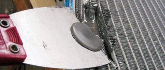
- 100 W or more. With this soldering iron you can solder a thick wire, a pan or even a car radiator. They are used only by professionals, and for obvious reasons are not applicable in everyday life.
If you plan to solder radio components, a 25-watt tool will be sufficient. To solder a regular wire, the power should be enough, but for everyday use you should choose a model with 35 W or higher.
Stands are often sold as a set. They not only keep your workbench free of solder stains, but also allow you to always control the position of the tool. When working, it should be on the edge of the table. It is important to monitor the power cord.
Solder
This special low-melting alloy typically uses the following substances:
Or any other metal with a suitable melting point. The most fusible ones have a melting point of up to 80 degrees, and the most stable ones have a melting point of over 900.
POS 61 brand solder. The most convenient type is a thin wire.
Flux
This is the name of a special substance that acts as a connecting link between the solder and the metal of the wire. It helps solder adhesion, and successfully protects it from oxidation and helps degrease. The most popular brand is LTI 120.
If necessary, it can be done independently. To do this, just dissolve rosin in alcohol (about 60 to 40% ) and shake thoroughly.
Additional tool
To solder conveniently and safely with a soldering iron, you should acquire the following items:
- Wire cutters. They bite off the wire, remove the insulation, and support the part during operation.
- File – for cleaning the heating part of the soldering iron
- Scalpel with tweezers. They will help you avoid burning your fingers when working with small parts.
Getting Started
The new soldering iron must be cleaned and tinned. You should plug it into the network for 15-20 minutes. In this case, the factory lubricant often begins to burn out, and the tool itself may smoke a little, this is not a big deal.
After warming up, you should carefully clean the work surface with a file, and then immediately dip it in solder. It is important not to let it oxidize. The tool is now ready for use.
It is important if the tip of your tool is made of metal ceramics. It cannot be processed with a file. There is a special damp cloth for this, and you need to gently wipe the surface with it.
How to solder a wire: process
It is very important to prepare the surface. There should be no foreign substances on it, such as grease, paint, varnish, or insulation residues. The success of all work depends on cleanliness. If there is anything, you should carefully clean it with a scalpel and wipe it so that no dust remains.
Next, you take a little solder with the tip and carefully solder it in the right place. This is not a very complicated process, but it requires a “tough” hand, and the very first time you are unlikely to get a beautiful and neat solder.
While working, it is worth remembering a number of rules:
- Soldering must be fast
- If you can't solder the wires right away, you should let them cool before the second attempt. This applies doubly to radio components or microcircuits
- The end of the tool should be applied with the entire surface, the process will be most effective
How to solder wires more securely? You should twist them before starting the procedure. After cooling, they are insulated with electrical tape to avoid short circuits during operation.
A good solder is shiny, even, and free of any cracks. Then it will last as long as possible, and you will not have problems with the device.
Safety precautions
How to solder with a soldering iron without getting burned? Safety precautions must be observed. Working with a soldering iron is not the best time to try your luck with violating safety rules. There are some simple tips:
- Clear the work surface of foreign objects
- Remove overly curious children and animals from the room
- Watch the cord - if you touch it with your foot or hand, there is a risk of burns
- If there are strangers in the room, warn them that you are working with a soldering iron on.
- Flux - just a little. If you use too much, it can splatter on your hand, or in the worst case, directly into your eyes.
- Each time you should take no more solder than 2 solderings . If you overdo it, it can drip onto the table, hand, or even worse, onto the soldered chip.
By following these simple rules, you will protect yourself from extremely unpleasant consequences. If you take your work seriously and don't leave your soldering machine unattended, there shouldn't be any problems.
Solder the wires properly
The further operation of the entire device depends on how the wire is soldered. Experienced craftsmen give a number of tips for high-quality and reliable soldering:
- If there is not enough solder, it will not be able to properly hold the parts together and fill all the gaps
- If there is insufficient amount of flux on the tip, the soldering site turns out to be heterogeneous and uneven, which negatively affects the result. This can happen when the instrument is heated, then the rosin evaporates before soldering is completed.
- When there is too much rosin, it can splash out and touch adjacent contacts or wires, and in the worst case, get on your hand
With experience comes the ability to heat the soldering iron to the desired temperature and use exactly as much solder as needed. Maintaining perfect balance, the solder independently takes the desired shape and flows correctly around the contacts. This is exactly what we need to strive for.
It is best to use soldering irons that have a thermostat. Then it is easy to maintain the desired temperature, which has a positive effect on the process and result of the work. A soldering iron without a regulator can quickly overheat, and its tip can turn black from oxidation. Then you have to turn it off periodically. Maintaining the required temperature is very difficult, and the soldering is not of sufficient quality.
How to solder efficiently with a soldering iron?
The best way to learn how to do something is to practice. Soldering is no exception. There are a number of exercises to help you master this undoubtedly complex but useful instrument.
You should take a bare or insulated wire (to practice stripping) and cut it into 12 equal pieces. To ensure that they are not too small, the optimal length is 30-40 centimeters (before cutting).
After cutting, you should take a soldering iron and form a cube from these blanks, using only a soldering iron and pliers. This will allow you to feel the instrument and get used to using it. Then the finished cooled cube should be taken in the palm of your hand and squeezed into a fist. The work is satisfactory if the adhesions remain intact. This can be practiced to keep your skills at a high level, even if you are an experienced professional and confident in yourself.
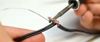
The second method of training to work with a soldering iron requires thin wire and a stripped cable. It needs to be wrapped around a wire, and then carefully soldered using a soldering iron and pliers. You should practice until you can solder the wires well the first time. After this, you should begin normal responsible work.
Regular practice will allow you to achieve significant progress in soldering very quickly. In no time, you will be able to repair your radio, wiring (with caution), or other home appliances yourself. But before that, you should entrust this matter to specialists so as not to risk expensive items.
Source: https://remont.youdo.com/articles/repair/paykapayalnikom/
Diagnostics and malfunctions of the multicontroller in a laptop
This article will talk about the microcircuit that controls the operation of the entire laptop, including turning it on. Its malfunctions lead to significant consequences for the user and most often require repair of the motherboard at a service center.
Multicontroller tasks
A multicontroller, or in English Super I/O (SIO) or Multi I/O (MIO) , in the slang “cartoon” (an EC controller is also found in the documentation), is a microcircuit that provides monitoring of voltages and temperatures, working with peripheral devices.
Such devices can be a keyboard, mouse, power button, lid closure sensor, etc.
Its main purpose is to control the keyboard (even in the diagrams it is designated as a KBC controller ), but over time, manufacturers began to load it with many additional functions, such as indicating the operation of the hard drive (LED on the front panel of the laptop) or controlling the frequency of the cooler .
It is to this microcircuit that all the contact paths of the laptop keyboard cable “come”. In fact, the multicontroller legs receive signals from almost all devices and chips in the laptop. The signal level can be constant 3.3V (high logic level), or changing in case of data exchange (measured by an oscilloscope).
In starting a laptop, it generally plays a primary role, since it is the signal from the power button that comes to it, and it is it that starts all the voltage sources and then sends a signal to the south bridge to begin initialization.
The multicontroller controls the switching on of PWM controllers that generate the voltages necessary for the laptop components to operate, and the switches that switch these voltages. A Flash chip with software (which sometimes has to be flashed) is connected via the multicontroller via the Firmware HUB or SPI protocol. The multicontroller may include real-time clock controllers, hard drives, USB, integrated audio interface, and LPC interface.
Types of multicontrollers
Multicontrollers are produced by the following companies: ENE; Winbond; Nuvoton; SMCS; ITE; Ricoh .
Only the latter differ greatly, at least in the soldering method; they are BGA.
Modern multicontrollers have 128 legs, but their purpose will vary greatly depending on the model of the multicontroller and even its revision. For example, KB926QF-D2 and KB926QF-C0. - two completely different multicontrollers.
Multicontroller malfunctions and their symptoms
The multicontroller often fails when the laptop is flooded with liquid or due to burnout of the keys that generate 3.3V. The second happens during power surges in the network.
The main symptoms of a malfunction of the multicontroller include incorrect operation of the keyboard and touchpad and the lack of startup as such. Also, a consequence of the incorrect operation of the “cartoon” are glitches in the periphery - incorrect operation of the sensors and cooler. Also, due to the fault of SIO, the hard drive and other drives may not be detected (USB operation is tied to the south bridge).
In diagnostics
Source: https://itprospb.ru/2018/09/diagnostika-i-neispravnosti-multikontrollera-v-noutbuke/
How to desolder a microcircuit from a board with a soldering iron
There are a wide variety of soldering tools, but not all of them are universal. For some purposes, specialized devices are required that have a special tip shape, operating principle, temperature conditions and other characteristics. When considering how to solder microcircuits with a soldering iron, it is worth paying attention to the tool used to perform this operation.
How to choose a soldering iron
Before learning how to properly solder a microcircuit, it is worth understanding the device model. A tool whose power will be in the range of 15-30 watts is suitable here.
This is quite enough to solder parts of circuits and boards without harming them. An acoustic soldering iron, characterized by its compactness and low heat capacity, is suitable for this task. It is also optimal for assembling circuits.
In addition, there are also industrial models designed for a wider range of operations.
When choosing which soldering iron to solder microcircuits with, you need to choose a model with a 3-way grounding plug. A technique with such a device avoids dissipation while current flows through the device. Heat is generated by closing the current in the tip. Nowadays there are enough models that can provide the required level of quality of work and have the required parameters, as the number of low-power analogues is increasing.
Soldering Station
This device turns out to be complex and requires a lot of experience to master it. There are several ways to desolder a microcircuit from a board with a soldering iron of this kind, but due to the higher power there is a possibility of causing harm. In the station, as a rule, the machine is connected to an alternating current source. Average power is about 80 watts. Once you master the soldering technique, it becomes much easier. Benefits include:
- long service life;
- the ability to accurately adjust the temperature with a relatively small error;
- possibility of unsoldering cables;
- soldering of aluminum, stainless steel, steel and other difficult-to-join metals;
- Soldering plastic pipes is easy, which makes the device more versatile than the soldering iron itself.
The station has a wide range of applications, so, for example, the task of “how to unsolder a microcircuit from a board” and similar ones do not cause much difficulty. Difficulty to learn and high cost limit the device's distribution to others. Compared to a regular soldering iron, the power consumption is much higher.
Source: https://svarkaipayka.ru/oborudovanie/payalniki/kak-vyipayat-mikroshemu-iz-platyi-payalnikom.html