DIY electrical wiring in a private house
The statistics are inexorable - about two thirds of all fires in cottages occur due to problems in the intra-house electrical network. Increased attention should be paid to electrical wiring in a private home. It must always be in good working order and initially correctly designed. You can easily install it yourself. The main thing is to correctly plan the wiring at the design stage of the house and install them before the interior decoration of the rooms begins.
It is customary to begin laying electrical wires immediately after the walls and roof are erected. To do this, you can call an electrician or do everything yourself. If the concept of “electricity” is not something scary and incomprehensible, then the second option will allow you to save a little on building your house. You just need to have basic skills in handling a hammer drill, pliers and a screwdriver, and also not forget about proper safety measures.
Typical wiring diagram for a private home
However, if you have doubts about your own competence in this matter, then it is better to entrust the installation of home electrical wiring to a professional. The cost of a mistake here is too high; a fire caused by a short circuit can destroy the entire cottage. You should install electrical wiring yourself only if you have clear confidence in your own abilities and knowledge. In this case, all wiring diagrams and selected wires must comply with electrical installation standards and regulations.
Step-by-step instruction
The general procedure for installing electrical wiring in a house involves:
- creating a plan for laying wires and placing electrical installation products in rooms;
- laying electrical wires in or on walls and ceilings;
- installation of a switchboard, distribution boxes and sockets with switches;
- switching all this into a single in-house electrical network;
- checking the functionality of the created system and putting it into operation.
There is nothing critically complicated here. The main thing is to choose the right wires so that they can withstand the load without problems, do not forget to install protection devices and carefully connect everything into a single whole.
Circuit markup
Before you start laying electrical wires, you need to mark their wiring on the walls. This is necessary to accurately understand the scope of installation work. Plus, “bottleneck” intersections of electrical wiring and other engineering systems will be immediately visible. For example, if there is a water pipe next to the cable, then something needs to be moved to the side. It is impossible to allow contact, even potential in the future, between water and electricity.
When making markings for electrical wiring, you need to take into account the presence of heating devices, ceiling height, location of windows or doors
According to unspoken rules, when marking electrical wiring, all lines are made strictly vertical or horizontal. This reduces the risk of damage to electrical wires during further finishing and makes them easier to find later during repairs.
Wall work
After marking has been completed, you can begin drilling and slotting work. But first you need to decide whether the electrical wiring will be laid in an open or closed way. In the first case, there is no need to trench the walls, but the wires will have to be covered somehow with decor. And in the second, they will be completely recessed into the thickness of the ceilings and partitions, but a lot of drilling and hammering will have to be done with a hammer drill.
Open wiring
When laid open, electrical wires are laid in tubes, special baseboards and cable ducts. They are made from fireproof and self-extinguishing plastics. If a private house is made of timber or logs, then you will have to choose this option. Wires cannot be installed inside wood.
Options for laying open electrical wiring
Closed wiring
Closed wiring involves laying cables in a hidden way in cavities inside walls and ceilings. To create such recesses in brick or concrete, you will have to work with a hammer drill and a grinder. There will be a lot of dirt. But then all the wires will be under a layer of plaster, which will make the interior more aesthetically pleasing.
A closed wiring diagram must be designed in the early stages of repairs.
Preparing the wires
Electrical wires are selected based on the power consumption of electrical appliances on a specific line from the switchboard. Typically, all electricity consumers in a cottage are divided into groups with approximately the same load, so that the cross-section of all cables in a private house is the same.
Kinds
According to the material used to make the wire cores, there are:
The first ones are cheaper, but tough. It is much easier to bend copper and place it in grooves, pipes and channels. According to their design, they can be single-core or multi-core. It is recommended to take two- and three-wire wires for your private cottage (the first for lighting, the second for sockets with grounding).
Types of wires for different circuits
Which ones to choose
You can now buy a wide variety of wires on the market. But for independent installation of electrical wiring, you should choose the option with double insulation VVG or PVG with the additional marking “ng” (does not support combustion). These are the most affordable power cables that are optimally suited for installation in buildings. They are available in stores in all sections. Required cables for the cottage with cores of 2.5, 4 and 6 sq. mm easy to find.
Input cable
The thickest wire in the electrical wiring of a private house will be the input wire, which bears the total load. Electricians from the power supply company now usually install self-supporting insulated wires (SIP) from the pole to the electrical panel. They install this cable themselves, and then they will have to install the introductory line themselves along the adjacent area and cottage.
If the shield is located on the street, then you will have to run a wire of 10–16 square meters into the house from it. mm. However, if you plan to install an electric boiler or powerful supply and exhaust ventilation or several air conditioners, the cross-section will need to be increased to 16–25 square meters. mm depending on the total power of all this electrical equipment.
Grounding
To increase safety, the electrical wiring in the cottage must be made with protective grounding. Its task is to protect people in their homes from electric shock. Connecting all household appliances in the home to grounded outlets is now the norm.
How to make a grounding loop in a private house
In addition to the wires, the grounding loop includes an RCD (residual current device) and a ground outlet. The first is installed directly in the electrical panel, and the second is usually made in the form of corners driven into the ground.
The grounding device and its wiring as a whole must comply with the requirements of the PUE. This is checked by employees of the supplying organization when putting the home electrical system into operation. If the grounding is carried out incorrectly, then they will simply refuse to connect the cottage to the network.
How to make grounding in a private house
Residual current system and circuit breaker
Another protective element in the house wiring diagram is a circuit breaker (difavtomat, AVDT). It should not be confused with an RCD (differential switch). They have different purposes and operating principles. But in appearance they are very similar.
The RCD disconnects the line only when a leakage current occurs. The difavtomat is more expensive and more complex to make inside. It also triggers in case of power overloads and short circuits. That is, the second device initially includes the first.
In most cases, for low-rise housing, a simple RCD is sufficient.
Distribution boxes
To simplify the installation of wiring in the house, distribution boxes are used. They connect wires connected from different sides. These mounting junction boxes reliably insulate the junction points of electrical conductors and, in case of overheating, prevent the spread of fire.
Installation and switching of cables and structures
Switching of wires among themselves and with sockets and switches is carried out by means of:
- twist;
- rations;
- terminal blocks with screw and spring clamps.
The most reliable is soldering. However, this is also the most difficult method. Twisting of cores is allowed only if they are made of the same metals. Aluminum and copper cannot be twisted. Such a connection will overheat and melt when current is applied. Most often, electrical wiring in the house is now assembled using various terminals. They are reliable and greatly simplify electrical installation.
Wire connection methods
Connecting sockets and lighting fixtures
When connecting lighting fixtures and sockets, the most important thing is not to confuse the wires. Phase to phase, zero to zero, and ground to ground. Other options are excluded here. And before connecting the house to the network and supplying electricity to consumers inside, it doesn’t hurt to check the insulation resistance on each line separately with a megohmmeter.
Connection diagram for sockets and lighting fixtures
Switchboard
The most complex and important element in a cottage's power supply system is the distribution board. Its installation is best left to a professional. All currents and voltages from the building converge in it. The slightest mistake in its assembly will inevitably lead to problems.
Connection diagram of devices to the distribution board
Testing and commissioning
Checking the entire electrical power supply system at home should also be delegated to a specialist. All the same, then you will have to invite experts from the electrical laboratory. Without their certificate, the house electrical wiring will not be put into operation anyway. And if they identify problems, they will then have to be called again.
Conclusion
It is not difficult to carry out the wiring of household electrical wiring, as well as the same ventilation in a private house, yourself according to the instructions above. The main point here is the preparation of the project with all power calculations and core sections, as well as the assembly of the distribution panel. And even a novice electrician-installer can lay wires around the cottage and connect them to sockets.
Read about our other materials:
Source: https://sdelat-dom.ru/remont/elektroprovodka/provodka-v-chastnom-dome/
How to connect wires in a junction box
No electrical wiring diagram can do without some kind of connections, branching wires or cables. There is a special box for this purpose. It is located under the ceiling and is a round or square box made of polymer material.
In this material we will tell you how to make connections correctly, demonstrate diagrams, photos and video instructions.
Why use a junction box
Wiring connection in the junction box
There are cases when, when installing electrical wiring, they neglect the installation of such distributors, considering that this is just a waste of time, since the box must first be installed, then the connections to it must be made, which will lead to additional difficulties. It’s easier to simply twist, insulate and simply plaster the wall. But here you need to think a little ahead, since in this case important points are missed:
- No free access to wires. For example, if the socket in your room does not work or the light has gone out, and after checking it turns out that the problem is a lack of voltage. How to check? Completely remove the trim? Tearing off wallpaper and plaster to get to the twist? This will ruin your renovation.
- If you want to install an additional outlet. It is not always convenient to connect it by laying wires from a previously installed outlet. Thanks to the distribution box, you can easily make new connections.
- The regulatory document PUE states that “places of connections and branches must be accessible for inspection and repair,” therefore the installation of such a distributor cannot be neglected.
- The absence of such distributors is contrary to fire safety standards.
As you can see, the distribution box plays an important role. But installing it is just the beginning. All that remains is to connect all the wires in it. What's the best way to do this? Let's look at some ways.
Types of connections
Types of wire connections
What is the task when connecting wires? Ensure good contact between the cores so that the chain does not break and there is no risk of a short circuit. In order to ensure this, you can act in several ways:
- Twisting.
- Crimping.
- Welding.
- Soldering with a soldering iron.
- Use of screw terminals.
- Bolted connections.
- Self-clamping terminals.
These are time-tested methods that you can use to ensure reliable contact. Let's take a closer look at each of them. You will learn how to properly connect wires using any of these options.
Twist
Twisting wires
Such twists in the distribution box are officially prohibited. The seventh edition of the regulatory document PUE, chapter 2, paragraph 2.1/21 lists all types of permissible connections, but there is no twisting in them.
And this is not surprising, since such a contact is sensitive to pulse current and has a high transition resistance. Over time, the contact will deteriorate and simply burn out.
Due to the fact that the contact area is small, heating occurs under heavy loads and the contact is weakened even more.
It is not recommended to use this type of connection, although some craftsmen still use it. If you choose twisting, all responsibility falls on you.
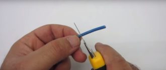
This option is chosen because of its simplicity. It is enough just to strip 10–20 mm of insulation and twist the wires together using pliers. This is what our fathers and great-grandfathers did. But such a connection is often unreliable, especially if an aluminum core is used.
Crimping with a connecting sleeve
Cross-sectional crimping of copper wires
A fairly reliable method that will require the purchase of a connecting sleeve. You need to select it based on the diameter of the bundle being connected. Depending on the wires you connect, the material of the sleeve itself is selected.
For copper wires the sleeve must be copper, for aluminum wires - aluminum. To ensure a reliable connection, the sleeve is crimped with a special tool called press pliers.
This technology is quite effective and is included, along with other methods, in regulatory documents.
Crimping connection of aluminum wires
To connect this way you need:
- Remove the insulation, taking into account the length of your sleeve.
- Twist the wires into a bundle and insert them into the sleeve.
- Compress the sleeve using press pliers.
- Insulate the twisting area with heat shrink or insulating tape.
It is not recommended to use pliers in such work, since the connection will not be reliable enough. It is much better to buy press pliers or borrow them from good neighbors.
Welding
Welding wires
This method can be called the most reliable and safe, because the wires are connected using fusion and become one. Due to the fact that the welding will not oxidize, such contact will not weaken over time. But to carry out such work you will need skills in working with welding equipment.
In addition to skills, you must prepare:
- 24 volt welding machine with a power of more than 1 kW;
- welding gloves for skin protection;
- welding glasses or mask;
- sandpaper for stripping wires;
- stationery knife for removing insulation;
- carbon electrode;
- flux, thanks to which the melt will be protected from exposure to air.
Welding copper to aluminum
After all the tools and materials are ready, all that remains is to do the welding, which will not be difficult. The work can be divided into several steps:
- Remove 60–80 mm of insulation and clean them using sandpaper. The veins should shine.
- Connect the wires using the twisting method, twisting one onto the other so that the ends are level with each other. It is recommended to make the length at least 50 mm.
- Pour flux into the recess of your electrode.
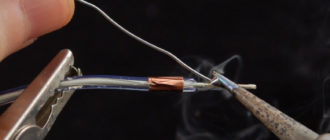
- Place the ground of the device on the bare wire, turn on the welding machine and press the electrode to the top of the twist.
- Hold the electrode until a ball called a contact point forms. This usually takes 1–3 seconds.
- All that remains is to clear the point of flux and insulate the welding site with heat-shrinkable tubing or electrical tape.
This type of connection will last a long time. In some old Khrushchev buildings, such welding lasted 50 years and consistently performed its function.
Soldering with a soldering iron
Soldering twists with a soldering iron
The method is very similar to welding, only in this case the wires are connected using solder. For these works you will need a soldering iron. To work you will need:
- soldering iron;
- fine sandpaper;
- rosin (flux);
- brush for applying rosin;
- tin-lead solder.
The operating procedure is the same as for welding:
- Removing insulation and cleaning with sandpaper.
- Twisting.
- Application of flux.
- Direct soldering. The soldering iron melts the solder, which should flow into the twist itself, reliably connecting the wires to each other.
Soldered wiring in the junction box with a soldering iron
Often copper wires are soldered using this method, but if you purchase special solder for soldering aluminum, you can also solder copper from aluminum.
Soldering is quite reliable, but is not recommended in areas where there may be strong heat. Moreover, under mechanical stress, the connection may weaken.
Using screw terminals
Connection of copper and aluminum wires
This method is fast, simple and effective. And most importantly, such clamps can combine dissimilar metals. For example, if you need to connect aluminum and copper conductors, which in itself, as you know, is contraindicated. These clamps are very simple and compact, and their cost may pleasantly surprise you.
Terminal blocks
To connect wires with clamps you only need to complete 2 steps:
- Remove 5 mm of insulation.
- Insert into the clamps and tighten the screw.
Melted terminal block contacts
That's all, as you can see, everything is very simple and fast. It is only important to control the force with which you clamp. If you tighten the screw too tightly, you may damage the wires. You need to be especially careful when working with aluminum wires.
Crimp lugs
The only disadvantage of a screw connection is that when working with a multi-core cable, it must be crimped with a special nozzle to ensure normal contact and integrity of the wire.
Bolted connections
Bolted connection
This connection is quite reliable, but cumbersome. It is not suitable for modern distribution boxes due to its dimensions, but for large old-style boxes it is just right. This method can be used to connect both homogeneous and dissimilar metals. The work is carried out as follows:
- A steel washer is placed on the bolt.
- The insulation is removed from the conductors and they are formed into a ring.
- The first ring is put on the bolt.
- Then comes another steel washer, which is placed on the bolt after the first.
- The second connecting wire is put on top.
- This entire “sandwich” is clamped with a nut.
- In the end, everything needs to be insulated.
It is this design that makes the contact bulky. If you need to connect several pairs of wires, then this option will not be the best.
Self-clamping terminals
This method can be called the most modern, popular and easy to use. All you need is to buy special terminals at the store. Inside these terminals there is a special paste that prevents metals from oxidizing. Thanks to this, various metals can be inserted into such joints.
The work is as follows:
- 10 mm of insulation is removed from each wire.
- The lever, which is located on the clip, rises up.
- The conductors are inserted into the connector.
- The lever lowers to its original position.
If your clamps do not have levers, they must be inserted until the terminal snaps into place.
Connecting wires with a terminal block without levers
We have looked at the most reliable methods by which you can combine wires in a junction box. This is a very important stage of electrical installation work, since 70% of errors during the work consist precisely in incorrect connection of conductors.
But if you, even without experience in such work, use the methods given in this article, you can easily do everything in accordance with the requirements of the regulations. But which of these methods to choose depends on your capabilities and desires.
This video shows how to connect wires in a junction box:
You will learn everything about sleeving wires or crimping lugs from the material provided in this video:
Scheme
Box diagram
Switch and socket block diagram
Connection
Junction box connection diagram
Connecting sockets
Switch connection diagram
Junction box
Connecting wires
Wire connection diagram in the box
Source: https://kakpravilnosdelat.ru/kak-soedinit-provoda-v-raspredelitelnoy-korobke/
Types and types of electrical wiring connections
Types of electrical wiring connections
Any electrical wiring diagram has a large number of connections. They are considered to be the “Achilles heel” of any electrical circuit.
Therefore, the closest attention should be paid to the correct installation of connections. And compliance with the rules of PUE (Electrical Installation Rules) when installing connections will allow you to eliminate fires and other unpleasant situations associated with your electrical wiring.
Types of electrical connections
First of all, let's understand the possible types of electrical connections. There are two of them: serial and parallel. Each of them has its own purpose and is used to implement various tasks.
Serial connection
Serial connection of electrical receivers
- First of all, let's look at the serial connection. It is used quite rarely, but also has its advantages. A connection is called serial in which the neutral wire of the first electrical receiver is phase to the second electrical receiver in the circuit. This can be seen better in the photo below.
- With this type of connection, the supply voltage is divided equally between each electrical receiver. That is, if the network is 220V, we connect two lamps with a serial connection - each of them will receive 110V. If you connect three lamps, then 73V, and so on. This feature of series connection is often used in garlands.
- The disadvantages of a serial connection include the fact that if a wire breaks in any section, the entire circuit stops working. That is, if one of the three bulbs connected in series burns out, none will light up.
Please note that when connecting in series, for example 220V lamps, the lamp with lower resistance will burn brighter.
If you screw in two lamps: one 60W, and the other 200W, then the lamp with a power of 60W will shine brighter.
Parallel connection
Parallel connection of electrical receivers
So:
- In most cases, electrical wiring diagrams provide for a parallel connection. With this type of connection, one phase and one neutral wire from the supply network is supplied to each electrical receiver. Again, this can be seen better in the picture below.
- This type of connection is used to connect 99% of electrical appliances. In this case, a break in the wire connecting to an electrical appliance de-energizes only this electrical appliance. The supply voltage corresponds to the specified one and can only change due to the connection of high-power devices.
- The disadvantages of a parallel connection include only a larger number of wires, as well as an increased likelihood of getting confused with a large number of connections. But this factor can be easily eliminated if you read these instructions to the end.
Wire connection methods
In accordance with clause 2.1.21. PUE, the connection of wires can only be done by welding, soldering, crimping and squeezing. As you can see, the favorite method of home-grown electricians, twisting, is not included in the list of permitted connection methods.
And of all the permitted methods presented, the most optimal for use at home is compression. This can be a screw, bolt or spring connection.
So:
- For the installation of bolted and screw connections, the industry now produces a large number of a wide variety of terminal connections. Their price is not high, and the ease of installation is at a high level.
- Separately, I would like to say about spring terminals. I myself am not a supporter of springs, spacers and similar connections, but I once had the opportunity to witness the testing of one of these terminal blocks.
- These were WAGO terminals. In the test setup, we gradually increased the current flowing through the terminal until our 4mm2 copper wire burned out. In this case, the current value was 100A. After that, we took out the terminal block and did not find any defects on it. This made me change my opinion about such spring terminal blocks, and therefore I advise you to take a closer look at them.
- It is also worth noting that a separate advantage of such terminal blocks is the ability to connect aluminum and copper wires. Under normal conditions, this can only be done through a brass insert.
Electrical wiring options
Now let's figure out what the electrical wiring should be and how to connect the wires. To disconnect a single-phase network, it is necessary to use a three-wire wire.
In this case, the standards from clause 1.1.29 of the PUE should be applied to facilitate installation and reduce the likelihood of wires being tangled.
Wire color code
Three-core wire should be used with the following wires:
- Phase wire - the color designation for a single-phase network is not standardized. For a three-phase network, yellow, green, red are phases A, B and C, respectively.
Note! For a three-phase circuit, PUE standards standardize not only the color scheme of the designation of each phase, but also their location in distribution panels of different designs.
- Neutral wire - for any network a blue wire should be used. When designating busbars or terminal blocks, the symbol “N” is used.
- Grounding wire - in any network a wire with longitudinal yellow-green stripes should be used. When designating busbars and terminal blocks, the grounding symbol is used.
Connection in the distribution panel
Now let's look at the types of electrical wiring connections in different parts of our electrical network.
Let's start with the distribution panel:
- First, let's deal with the phase wire. It must be connected via a protective device. These can be fuses, plugs, but most often circuit breakers are used. The power wire to circuit breakers is usually supplied from above, but you connect from below.
- The neutral wire, according to the PUE standards, should not have switching devices. Therefore, usually a separate terminal block is organized for it in the side of the panel. We connect the blue wire of our wire to it.
- The same rule applies to the ground wire. Only for it you should create a separate terminal block. We connect our yellow-green wire to it.
Connection of RCD for all consumer groups
Let us separately focus on connecting the RCD. To do this, we need to use not only the phase, but also the neutral wire. And the circuit largely depends on the location of the RCD installation.
If you install RCDs on all groups of your electrical network:
- In this case, the phase and neutral wires from the meter are connected to the RCD inputs. It is important here not to confuse and connect the neutral wire to the terminal marked “N”. Otherwise the RCD will not work.
- We connect the phase wire at the output of the RCD to all circuit breakers that supply individual groups.
- We connect the neutral wire at the output of the RCD to a bus or terminal block, from which the neutral wires of all groups are connected.
If you install an RCD on a separate group:
- In this case, the phase wire for the RCD input is taken from the group circuit breaker.
- The neutral wire for the RCD input is taken from the neutral bus of your distribution panel.
- From the RCD terminals, the neutral and phase wires go directly to consumers.
Connection in junction box
Connecting the electrical wiring to the blocks, subject to the above standards, will also prevent you from getting confused. The only difference here is the connection of lamps and sockets, but they are insignificant.
When connecting sockets, we just need to use terminals to make a branch of the phase, neutral and ground wires:
- To do this, the incoming wire is cut and each core is connected to a separate terminal block. To connect one socket you need three terminals, two sockets - four, three - five, and so on.
- Now we connect the phase wire of the incoming wire to one terminal. The group wire going to other connections is connected to the second terminal. We attach the phase wire going to our socket to the third terminal.
- We perform identical operations with the neutral and ground wires.
Connecting lamps is somewhat complicated due to the presence of a switch.
- If you volunteered to connect the lamps with your own hands, then at the first stage we do the same operations as when connecting sockets. That is, we cut the cable and connect each core to different terminal blocks. You can also immediately connect the wire going to other electrical receivers of this group.
- According to the PUE standards, the lighting circuit breaker must disconnect the phase wire. Therefore, from the terminal block of the phase wires we make a connection to the switch.
- If you have a one-button switch, then the output from the switch will be one wire. If there are two or more buttons, then two or more, respectively. We'll look at a one-button switch to make it easier to provide information. For two, three or more push-button switches, the connection diagram is identical.
- The wire connected to the switch terminal is sent back to the junction box. Here we install another phase terminal block, to which our wire is connected.
- Now take a three-core wire, which is connected directly to the lamp. The phase core of this wire is connected to the phase terminal block of the wire coming from the switch. The neutral conductor is connected to the terminal block of the neutral conductors, and the grounding conductor is connected to the terminal block of the grounding conductors. That's it, the connection of our lamp is completed. If you watch the corresponding videos, this process will become even more clear to you.
conclusions
We hope our instructions will allow you to easily connect an electrical network of any complexity. After all, basic compliance with the rules of the PUE can significantly simplify this process and eliminate the possibility of error.
Source: https://Elektrik-a.su/energii/v-zhilyh/vidy-soedinenij-elektroprovodki-24
Correct twisting: features and types of connection of electrical wires
Perhaps the most cherished dream of any electrician is electrical wiring without intermediate breaks. So that a separate wire passes from the panel to each switch or socket without connections. But this is a pipe dream - not many people will like the fact that dozens of wires will be connected to the electrical panel. And it gets expensive - you need a lot of wire. That's why the wires branch and connect.
Typical wiring in an apartment can have over a hundred connections. And electrical wiring faults, as a rule, appear precisely in these connections. Therefore, great attention must be paid to the correct connection of wires.
Wire connection methods
methods are used to connect wires :
- pressing (crimping);
- twist;
- PPE clips;
- screw terminals;
- welding;
- soldering;
- bolted connections;
- WAGO terminals.
What is better to choose for twisting wires?
To begin with, let's turn to the PUE. Paragraph 2.121 says that correct termination, branching and connection of cable cores and wires must be carried out using soldering, welding, pressing or clamping (bolt, screw, etc.). That is, of all the above options, only twisting is illegal. But twists will exist until the day there is electricity. Therefore, we will tell you about all connection options.
Soldering
This is the most labor-intensive option for connecting wires, which requires some experience. Better quality twisting than poor soldering. Therefore, we will provide general information to those who have sufficient skills.
Before soldering, the cable is cleaned of oxides; if necessary, it is tinned, screwed (maybe not as tightly as when twisted), treated with flux and soldered. You can solder both aluminum and copper wires if you choose the right solder and flux.
There is no need to choose an acidic active flux - it will certainly remain on the wires and will destroy the connection over time. Soldering takes quite a lot of time, but the fastening is one of the most reliable.
PPE connection
This is a plastic cap with a square metal wire inside, installed in a spiral cone. Often its cavity is filled with a special lubricant that protects the wires from moisture and prevents oxidation. When connecting wires using PPE, it is important to choose the size of the clamp correctly, taking into account the number and diameter of the wires being connected. As a rule, this information is located on the packaging.
For fastening, the insulation is removed from the wires to a size slightly smaller than the length of the cap, laid together and the PPE is screwed on top. Moreover, the edges of the square spring remove the layer of oxides from the surface of the core, its cone moves apart and, thanks to its elasticity, reliably clamps the wires together. For reliability, some electricians prefer to first do the usual twisting and then install the PPE.
The advantage of PPE is the simultaneous fastening of wires and insulation of their connection area. Disadvantages include weakening of the spring over time, which leads to increased contact resistance. It is not advisable to install PPE in high-current circuits.
Screw terminals
This fastening is very widely used when connecting switches, electrical sockets, lighting devices and other electrical fittings to wires. Screw clamps are often used when assembling electrical panels , as they make it possible to carry out neat and quick installation.
The obvious advantages of clamps include the absence of the need to isolate the fastening. Using these clamps, you can fasten wires made of various metals (copper and aluminum).
Of course, there are also disadvantages. It is not possible to install a multi-core cable into the clamps - it must first be crimped or soldered. In addition, screw terminals require maintenance - they need to be tightened from time to time to prevent the connection from loosening. In general, if there is a free approach to the connection areas, then screw terminals are an inexpensive and reliable solution.
WAGO terminals
This fairly new type of fastening is based on the installation of insulated spring clamps manufactured by the German company WAGO. These WAGO connectors are manufactured in a large assortment and include connectors of various designs, for various purposes, for a wide variety of cross-sections, types and numbers of wires. Therefore, it is advisable to buy WAGO connectors in a specialized store and always check the certificates.
The main advantages of these connectors include quick and easy installation without any special devices, as well as simultaneous insulation of the connection and fastening of the wires.
WAGO fasteners have all the necessary tests, are certified and are widely used both in our country and around the world. Therefore, there are no serious reasons not to trust them. All cases of any problems are due to the wrong choice of WAGO fastening for a certain load or the installation of fakes. It is these points that you need to pay great attention to when using for connection.
Crimping
This option means connecting the wires using crimping with a lug or tubular sleeve. Tips and sleeves are made for cables and wires with a core diameter of 2.6-250 square meters. mm.
Crimping is quite convenient for “set and forget” fastenings, but requires special equipment and the correct selection of sleeves for the specific diameter and number of wires being fastened.
The tools used are crimping presses, as well as manual hydraulic, electric and mechanical pliers.
For crimping, select the required sleeve; if necessary, adjust or select the working end of the tool. The insulation is removed from the wires, the conductors are cleaned and lubricated with a special paste, the sleeve is put on and clamped. A high-quality tool clamps the entire length of the sleeve in one pass; cheaper ones require several clamps at a certain distance from each other. After this, the sleeves are insulated with heat-shrinkable tubing or insulating tape.
Bolt fastenings
Used in circuits with high voltage . A washer of the required diameter is placed on the bolt, then the wires are wrapped around the bolt, another washer is put on and the whole thing is carefully clamped with a nut. If you install an additional metal washer between the cores, you can connect copper and aluminum wires together. In residential electrical wiring, this option is almost never used due to its bulkiness.
All completed installation connections of any type must be accessible for further maintenance and inspection. Correctly selected connection of wires is the main guarantee of the reliability of electrical wiring in an apartment or private house.
Source: https://stanok.guru/oborudovanie/raznoe/pravilnaya-skrutka-i-vidy-soedineniya-elektricheskih-provodov.html
Is it possible to connect wires of different sections - advice from an electrician - Electro Genius
It may seem to some that there is absolutely nothing complicated about this, but later, if you do not pay due attention, this can lead to the wiring failing, and even the impossibility of restoring it without major repairs.
That is why it is necessary to know in what cases and what joining technique should be used in order to achieve the best result.
How to connect two wires
Connecting a pair of wires is the most common case when a consumer needs to create a circuit, but cannot do without a break.
Depending on the operating conditions, the following types of connections are distinguished:
- · soldering – a reliable connection, used in low-voltage circuits, electronics and household networks with low load;
- · mechanical clamp – used in household and industrial networks; depending on the load power, the corresponding types of clamps are used;
- · mechanical twisting is the simplest and most accessible method, can be used in household networks.
Most often, in domestic conditions, especially when it is necessary to quickly make a connection, and there is nothing else at hand, twisting is performed, and for mechanical strength it is also combined with soldering, but on the condition that powerful heating devices are not connected to the line, which may cause the solder to melt.
If this is still expected, it is recommended to leave the twist in its original position, or use a clamp.
How to connect 3 wires
Quite often a situation arises when it is necessary to connect not two, but three wires, for example, when supplying energy from one phase to two consumers at once, and in such cases, the most convenient method of connection is a mechanical clamp.
Depending on how large the load will be, it is necessary to select the appropriate model of the clamp used. The simplest option is a metal sleeve into which wires are inserted on both sides, on the one hand supplying, and on the other, pre-twisted together, feeding.
If one of the wires has a larger cross-section, then it is this wire that is inserted into the sleeve without twisting. After the wires are inserted, the connection is secured with clamping screws.
If the wires are of small cross-section, then the usual twisting of all three is used; pliers are used to ensure a tight connection. The twisting area can be covered with a plastic threaded cap.
How to connect wires of different sections
Quite often it is necessary to connect wires of different cross-sections; this can be seen in the distribution boards of residential buildings, when branches go from the supply core to each of the apartments.
The difference in cross-sections, and sometimes significant, primarily implies a very tight connection in order to avoid heating in this place.
The most commonly used connection method in this case is twisting. Despite the seeming backwardness of this method, many experts can confirm that if the twisting is done well, it can withstand a much greater load and temperature than a clamp.
It is advisable to do twisting in the case when it is necessary to make a branch from the main line that does not have a break. In this case, in a selected area, the insulation layer is simply removed, and the end of the connected wire is wound around the core of the line.
When a wire break does occur, mechanical clamps, or terminal blocks, or any other device that is structurally designed to connect such cross-sectional sizes can be used.
Source: https://orenburgelectro.ru/drugoe/mozhno-li-soedinyat-provoda-raznogo-secheniya-sovety-elektrika.html
Connecting the power supply branch of a private house to the overhead line
From a transformer substation or public step-down transformer, the power supply is distributed through overhead line (OHL) wires throughout the village where your private home is located. A branch (input) is made from the overhead line to a private house.
The route to the house can be done by air, the so-called “airlift”, or by a trench in the ground. The choice of the type of power supply branch to the house depends on the geodesy of the area and the distance of the house from the overhead power distribution lines.
, from the presence of forest plantations around the house, from the passage of underground utility routes near the house, etc.
But no matter what type of power supply branch to the house you choose, you have to connect the branch cable (connections) to the overhead line (OHL) wires. Let's look at this in more detail.
Important! The connection of the power supply branch to a private house from the overhead line must be done by specialists from the energy supply organization. However, it doesn’t hurt to understand what is being offered to you as a thrifty owner.
Connecting an air supply branch to a private home
The overhead power supply to the house is carried out with insulated SIP wires or electrical cables VVGng, AVVG, etc. on a supporting cable.
Overhead distribution lines can be made of bare wires 4×70+35 mm2 (designated VL) or insulated SIP wires 3×70+95+25 mm2 (designated VLI).
The overhead line connection should be made at the overhead line support closest to the house. If the nearest support from the house is more than 25 meters away, then you need to install your additional support at a distance of no more than 15 meters from the overhead line and no more than 10 meters from the house.
If the overhead line is laid on insulators, the connection and branching of the wires must be made directly at the insulators or on them. Connecting a branch with self-supporting SIP wires and electrical cables on a supporting cable are slightly different.
Connecting SIP wires to an overhead distribution line
SIP wires do not require supporting cables and are self-supporting. Connecting SIP wires to overhead lines can be divided into four stages.
- Secure the wires to the house with an anchor clamp;
- Stretch the wires between the house and the support;
- Secure the SIP wires to the support with an anchor clamp;
- Connect the branch wires to the overhead line wires.
Attaching SIP wires to the house
To fasten wires to load-bearing structures (walls, poles) using anchors or tension clamps. (Look at the photo)
This is essentially a wire clamp, with a loop for attaching to a hook. The hook is attached to the wall of the house or to a support pole. The entire process of connecting a branch to a house via an overhead line can be described as follows.
- Two hooks or anchor brackets are attached: one to the wall of the house and the second to the support post.
- Using a tension clamp, the wires are secured to a hook on the wall of the house.
- Using a roller pulley (roller block), the SIP wire is stretched between the house and the support to the desired tension.
- The end of the wire is secured in an anchor (tension) clamp with a loop.
- The loop is put on a hook mounted on a support. Instead of a hook, an anchor bracket can be used.
Important! The hooks for attaching the anchor clamps should be secured to the main structure of the house and not to the siding or stucco.
Connecting the SIP wire to the “bare” wires of the overhead line (OHL)
To connect the SIP wire to the bare wires of the overhead line (OHL), you will need a special outlet clamp to connect the SIP wire to the bare wires. Using these clamps, the SIP wires are connected to the overhead line.
Connecting SIP wire to insulated overhead line wires (VLI)
To connect the SIP wire to the insulated wires of the overhead distribution line (VLI), you will need a special piercing branch clamp to connect the SIP wire to the insulated wires. The piercing clamp does not require stripping the insulation of overhead line wires. With the help of such a clamp, SIP wires are easily connected to the overhead line.
Connecting the branch to the house with cables on a supporting cable
The steps for connecting the cable on the supporting cable are the same as for connecting SIP wires. Only between the house and the support is the supporting steel cable stretched. To attach the cable to the wall of the house and to the pole, anchors with loops for cables or tension couplings are used, which are attached to the anchors with coupling connecting strips (see photo).
The wires themselves are connected to the wires of the main line using special die clamps to bare wires or piercing clamps to insulated wires. And the cables are secured to the cable with cable banding straps.
I will dwell in more detail on attaching anchors to the wall of the house and to the pole.
Attaching anchors to the wall of the house and to the pole
Depending on the cross-section, and therefore the weight, of the wires (cable) used for the branch, several options are used for attaching anchors to a wall or support.
Bolt hook. It is screwed into a special dowel, which is driven into a pre-made hole in the wall or support. The hook should be screwed into the main structure of the house, not into the sheathing. Suitable for light branch cables. For wooden structures, a hook with a screw tip is used.
Fastening anchors with through bolted connections to the wall. These are more reliable fastenings of anchors to the wall (see figure A and B).
Fastening anchors to the wall using an opening T-shaped fastening. A hole is drilled in the wall. When closed, the T-bar is a straight bar. After inserting into the hole, the mount opens and is held against the wall by the upper bar of the mount. (See Figure C)
Fastening anchors to the pole with crimping clamps. This is the most reliable way to attach anchors to a support post. The figure clearly shows the girth fastening technology. I will only add that instead of corners and studs, you can use a metal strip with a welded hook for the anchor. (In the figure “Installing anchors on column girths”)
Connecting a branch cable to the house, descending into a trench along a support
When running a branch cable into a trench leading to the house, you need to protect the cable on a support with a metal pipe or metal casing. From the ground, the cable protection must end at a height of at least 2 meters.
The connection of the branch cable with the distribution wires of the overhead line must be done by soldering, using heat-shrinkable tubes for insulation, and the place where the insulation is removed must be protected with a special heat-shrinkable glove.
Sometimes you have to make a turn when the power supply branches to the house. The figure below shows the rotary connection of SIP wires or cables on a supporting cable.
Elesant.ru
Source: https://elesant.ru/podklyuchenie-doma/podklyuchenie-otvletvleniya-elektropitaniya-chastnogo-doma-k-vozdushnoj-linii
How to branch one wire into 3 separately hanging lamps? — Website about
- Video author: Popular electronics / For the home electrician
- Author's channel: https://www..com/channel/UC9h7su1FcuWUaX9SIIGD7Og
We have to do these procedures in the process of repairing apartment electrical wiring or when laying new electrical wiring, as well as when connecting wires in junction boxes.
In order to splice, branch or connect electrical cables, we need the following tools: pliers, wire cutters, a construction knife, electrical tape and, of course, the wires themselves. It is advisable to have two rolls of electrical tape of different colors.
We will show you the process of connecting wires simply using scraps. These wires will be in your wall either in electrical plastic boxes or laid in some other way.
Connecting electrical cables
Let's start by connecting the electrical wires. Let's assume that we have three wires going into the electrical box, and they need to be connected to each other.
How it's done? First, you need to cut off the excess cable and leave the cable at such a length that it does not interfere with the placement of the cables in the electrical box, but at the same time it is not too short, because a cable that is too short cannot be properly stripped and cannot be connected properly. It should extend about 5 cm out of the box, then we will trim it anyway.
Now we do the following: we strip each cable to a length of approximately 2–2.5 cm. We carefully cut it, trying not to damage the inner conductor. Here the technology is the same for all types of conductors - aluminum, copper, single-core and stranded.
We remove the insulation without damaging the cable, then be sure to clean the conductor, because in most cables it is coated with a thin layer of varnish to prevent corrosion of the conductive layer. We clean it with the end of the knife specially designed for this purpose, so as not to cut our hands or dull the knife.
We twist the veins. You can twist them in any direction you like.
To do this, you can use pliers or your own hands, if you don’t mind them. Naturally, only multi-core cables are twisted. If you have a single-core cable, then we simply strip it. We perform the same procedure with the second cable, then with the third: remove the insulation, strip it, twist it. Then we take two cables, lean them against the insulation and tightly twist them like this:
- Next, we apply the third cable, also insulation to insulation, and as tightly as possible - this is very important for the further operation of your electrical wiring - we wind it onto the other two cables.
Most electricians recommend that after twisting, you cut the twist where the last cable ended. It ends a little earlier than the other two.
Why is this being done? First, we bite off the excess. We don’t need a strongly protruding twist, it’s inconvenient to insulate, and it won’t fit well in the box. Secondly, we get something like cold welding.
This is also very important, as it improves electrical contact and, therefore, the functionality of our wiring. With such a connection, our wiring will work much longer. Then we isolate the twist.
Why is it recommended to use two colors of electrical tape? In an electrical network, as we know, there is a phase and a “zero”.
In order not to constantly check with an indicator probe whether it is phase or “zero,” it is best to mark the phase wire, for example, with red or brown electrical tape.
As a rule, phase wires in electrical networks are designated with these colors, and the neutral cable is either black or blue. If you don’t have blue or black electrical tape, you can use yellow or some other kind.
We take electrical tape, start about 1 cm along the insulation and wrap it as tightly as possible.
Then we wrap a second layer of electrical tape to create reliable insulation. The insulating tape will not only insulate the cable, but also hold it together, because with aluminum strands it often happens that the strand weakens over time.
Aluminum oxidizes slightly and twisting becomes unreliable. If we insulate everything tightly, then the electrical tape will additionally secure this twist. The twist will last much longer; there will be no need to disassemble it after 5-6 years and twist it. Twisted and cut.
This can be done with pliers or a construction knife.
- One more point: it is recommended to insulate electrical boxes in such a way that there is access to the electrical contact:
What is it for? The cable remains insulated, that is, a short circuit will not occur, but when repairing this wiring, it will be very easy for you to check whether it is a phase or “zero”, whether there is a phase or not.
This check is easy to carry out, but the insulation remains reliable and does not in any way affect the performance of the connection.
This is very convenient during repairs, since you don’t have to unwind the insulation and, therefore, everything can be checked under voltage - you don’t need to turn off the electrical packages and then turn them on again. They just opened the box, checked it, and that’s it.
Thus, we connected three wires. In the same way, you can connect a larger number of wires, usually up to six. It will no longer work, because too much twisting becomes non-functional and inconvenient to use.
Splicing electrical cables
The cables have to be spliced in the electrical box or outside it. To do this, you need to strip these cables in the same way as in the previous example. We make cuts, remove insulation, and strip the cables. In order to splice the cables, we lay them crosswise:
We twist them, about 3-4 turns, and we get a fairly strong twist:
You can use pliers for this work. We work with them, trying to ensure that the cable does not diverge.
If desired, if you have a soldering iron, you can also solder this connection to give it additional strength. If you don’t have a soldering iron, you can do it this way. We begin to isolate the resulting twist. We take electrical tape, start about a centimeter before the connection and insulate it.
We also go about a centimeter from the other edge and return to improve the dielectric properties of our connection with a second layer. We bite off the excess electrical tape.
- That's it - we spliced the cable.
Electrical cable branch
Suppose we have wiring in the wall that has already been installed earlier, but we forgot to install some kind of socket or switch. In order to install them, it is necessary to make a cable outlet, that is, connect to our central core.
For electrical connections, it is better to do this in a box, but in any case you will have to connect it with a branch. How to do it?
We take the outlet cable, remove the insulation in the same way as in the previously described cases, strip it, twist it. Then we prepare the central core.
To do this, we remove the insulation in a certain area, also 1.5–2 centimeters, but the peculiarity here is that we remove the insulation not from the edge, but in the middle of the wire.
Since this cable is not wound, the length of the stripped section will be shorter. We cut through the insulation in a circle on one side and the other:
- Now, carefully, so as not to cut yourself, cut the insulation in the center, remove it and cut off the excess:
- Here we have a prepared cable:
We clean it, if possible, twist it. But if the cable has already been laid, then it may not be possible to twist it. We have prepared the cable, take a branch, apply it to the left edge, insulation to insulation, and wind it tightly.
- We try not to let anything stick out. The result is a fairly reliable branch:
- We take the electrical tape, start a centimeter before the twist, go through one layer, move smoothly to our connection, and also go about a centimeter along the insulation.
- Returning back, we wrap it not on the central cable, but on the branch:
- Trim off the excess tape:
- We ended up with this branch:
The central cable remained in its place, and the branch went to the outlet or switch. It should be remembered that all these procedures must be done with the voltage turned off! Take care of your health, and maybe your life. Such work with electrical wiring does not forgive mistakes!
Source: https://orensbyt.ru/osveshhenie/kak-sdelat-razvetvlenie-odnogo-provoda-na-3-otdelno-visyashhih-svetilnika.html
How to connect to a wire without cutting it?
A branch wire is used to add a new line to an existing electrical network. For example, you have a cable running along the wall that you need to connect to to connect a new outlet. In this case, it is not necessary to cut the core and twist the three ends together. A safer and more durable way is to use special couplers, which we will talk about next!
Squeeze the nut
When we looked at the basic ways of connecting wires in a junction box, special attention was paid to a special nut-type clamp. The product has a fairly simple design, but despite this it allows you to make the branch reliable and durable. The compression nut consists of a carbolite body, a steel die and a plate, which actually presses the cores with four screws.
The compact size of the nut, as well as its low cost, makes it one of the most popular power line taps. In turn, the disadvantages of the product are low tightness (degree of protection IP 20), as well as the inability to branch live wire cores. It should also be noted that a very important advantage of the “nut” is the ability to qualitatively connect copper and aluminum conductors with a cross-section from 1.5 to 150 mm2.
All you need is to place the stripped contacts in a special die and carefully tighten the screws with a screwdriver, then snap the housing into place. You can learn more about nut-type compression from our article.
Piercing clamps
An improved model of nut cable compression are piercing clamps. Disposable products, however, allow you to make a wire branch without cutting and even without peeling off the insulating layer when splicing. The design of the clamp is represented by a hexagonal head, which tightens the conductors, as well as contact plates with teeth, which actually pierce the insulating material.
The advantage of these products is as follows:
- You can branch wires from an overhead line (OHL) even under voltage, without fear for your safety. This is due to the fact that the contact plate is reliably insulated from the clamping bolts.
- The housing of the products is sealed and reliably protects the connection point from bad weather conditions.
- The clamps are easy to use and have a long service life.
- Low cost of production.
- Possibility of bonding copper and aluminum conductors.
As for the disadvantages, the main thing is only the “disposability” of the product, but this point is very controversial, given the durability of this method of branching wires without breaking.
Installation is carried out as follows:
Instructions for installing the piercing clamp
Clamp type OB
When repairing or replacing electrical wiring in an apartment, you can use another pretty good option for splicing wires - using OB type clamps. The products have a simple design and an equally simple operating principle - the cable is placed in a special latch, which uses a brass connector to pierce the conductor insulation layer. As a result, in a matter of seconds you can make a good branch from the main power cable (for example, to a socket).
As for the disadvantages of latches, the main one is the limited conditions of use - the cross-section of the cores should not exceed 6 mm2. In turn, for home electrical wiring, such a cross-section will be quite sufficient even for connecting a powerful electric stove.
Instructions for using the latch to branch the wire without cutting:
The simplest version of a coupler
Terminal block DKS
A more outdated method of branching a wire is to use DKS terminal blocks. It is not recommended to use compact terminal blocks, because... in this case, it is impossible to do without cutting and tearing the main core.
In addition, the terminal block also has such disadvantages as poor sealing and the need to periodically tighten the clamping screw, especially if the conductor is aluminum.
As a result, you do not get any important advantages when splicing and at the same time you get several serious disadvantages.
Terminal Blocks Overview
Grandfather's twist
Well, the last method of branching wires that can be used is to twist a new line from the passing main line without additional soldering or welding. In this case, you must first strip the insulation of the conductors, after which the branch line must be screwed tightly onto the main line (as shown in the picture).
Please note that when creating twisting, it is prohibited to connect aluminum and copper conductors. Conductors must be made of the same metal. According to the PUE rules, using this method is highly discouraged due to its unreliability. Read about how to properly twist wires in the provided article!
So, in fact, we looked at the most popular methods of branching wires without breaking or cutting. Now you know how you can make a high-quality splice of two power lines. Our advice is to use piercing clamps, which are the most trustworthy of all the options!
Source: https://otoplenie-help.ru/kak-podsoedinit-sya-k-provodu-ne-razrezaya-ego.html
TV splitter - how to make it yourself - Do It Yourself
Owners of several TVs in the house often wonder how to split the signal without degrading the quality of the broadcast. A properly selected and connected antenna splitter creates a television cable distribution structure from one source without significant loss of signal power.
Characteristics
When selecting any equipment, you must proceed from both the characteristics and the individual features of its installation in a specific situation. Antenna splitters were no exception. How to choose the correct divisor according to your parameters?
Antenna splitter characteristics:
- Bandwidth. Shows the frequency range transmitted by the divider. For terrestrial TV, the operating frequency of the divider should be in the range of 5-1000 MHz, for satellite TV - from 5 to 2500 MHz. A satellite splitter can be used to transmit over-the-air digital and analog signals.
- Number of exits. The antenna splitter can include up to eight of them. Select equipment based on the number of connected TVs. You can connect a splitter with a large number of outputs to expand your television network.
- Attenuation level. An important indicator that determines the amount of reduction in the power of the transmitted signal. The lower this indicator, the more insignificant the output losses will be.
- Availability of RF amplifier. An antenna splitter with a built-in RF amplifier is called active. Such a divider is capable of not only maintaining the power of the incoming signal, but also increasing it. It is worth considering the need to connect power to the active divider.
Recommendations for selection
If you intend to split the signal between two TVs, all you need to do is purchase a passive splitter with two outputs and a good TV cable. The attenuation will be 3-3.5 dB at each output, which will not have a significant impact on quality.
If you plan to split the signal into three or more TVs, then to select an amplifier you need to draw up a wiring diagram so that the input to each TV has the same signal level.
It is imperative to take into account the level of attenuation not only in the divider, but also in the cable.
The use of an active amplifier in this case guarantees a reduction in losses from separation, length and quality of the cable used.
DIY antenna splitter
The antenna splitter circuit does not contain anything complicated, and it is technically quite possible to make it yourself. Any divider consists of a bridge with a ferrite transformer and capacitors.
But is it worth making it so complicated? The manufactured device will only be suitable for splitting an analogue television signal, and ferrite rings can only be found in specialized stores.
It makes sense to constructively modify an inexpensive Chinese-made antenna splitter or convert a passive divider into an active one. Many Chinese no-name manufacturers save on installing additional resistors and SMD capacitors. The best option would be to buy a divider from proven brands such as Alda, Rexant or Lans.
Source: https://cheboksary-otdelka.ru/drugoe/televizionnyj-razvetvitel-kak-sdelat-svoimi-rukami.html
How to branch an electric wire - We build and repair
A branch wire is used to add a new line to an existing electrical network. For example, you have a cable running along the wall that you need to connect to to connect a new outlet.
In this case, it is not necessary to cut the core and twist the three ends together.
A safer and more durable way is to use special couplers, which we will talk about next!