How to connect wires correctly
According to modern rules of the PUE 7th edition, it is allowed to use four methods to connect electrical wires:
Let us consider in detail each of these connection methods.
1. Terminal connections
When installing electrical wiring, it is necessary to use high-quality products for connecting and branching wires, because reliable installation is the key to electrical safety.
It is advisable to use copper wires, but in everyday life you sometimes have to connect copper and aluminum wires.
The main rule when connecting electrical wires in this way is that you cannot connect copper (Cu) and aluminum (Al) wires directly; they can only be connected using various types of brass terminals.
Terminal connections are suitable for wires made of different types of materials, as well as for wires made of the same metal. The terminal itself is made of brass; in high-quality products it is also filled with gel, which prevents the oxidation of the wire. Terminals are most often produced in the form of blocks, assemblies of two or more terminals each.
Terminal blocks, otherwise called terminal blocks, are of three types based on the method of securing wires:
- Spring,
- Screw,
- Knife.
Spring clamps
Terminals of this type are called clamps, because the wire is clamped inside the terminal with a spring, ensuring reliable contact. In some clamps, the contacts are filled with a lubricant to prevent the appearance of an oxide film on the wire, which guarantees reliable contact in the future.
When installing electrical wiring, you must use clamps designed for the appropriate current, wire diameter, and voltage. All this data is on the clamp body.
WAGO clamp. In practice, wires with insulations of different colors can never be connected. Each specific clamp combines wires for a specific purpose.
WAGO inside
Similar clamps are used to connect mainly single-wire conductors of electrical wires, although there are also models of spring clamps for multi-wire conductors.
There are different types of clamps and for different numbers of electrical wires. Back to listing types of terminal clamps.
It is correct to use Wago clamps when branching the neutral and phase conductors. To branch from the protective earthing (PE) conductor, it is necessary to use a different type of clamp, because The main core must not be torn, which is impossible to do with the Wago clamp. For this purpose, a knife-type clamp can serve, for example. About them a little below.
Screw type terminal blocks
Terminal blocks
Screw-type terminal blocks are available for connecting electrical wires of different diameters. Not used for connecting stranded electrical wires unless they are crimped with brass lugs. The number of conductors clamped simultaneously is no more than 3. The wires for connection are stripped of insulation to a distance sufficient to be clamped under both screws.
When installing copper wires in junction boxes, such terminals are convenient because the connection is compact and can be easily placed in the junction box. However, due to the rigidity of the copper conductors, when the terminal is placed in the mounting box, non-contact may occur in the connection. In this case, Wago clamps are preferable.
Screw clamp for DIN rail
Electrical parameters on the housing
Another disadvantage of screw terminals is that they must be subject to annual inspection, i.e. tighten once a year, and Vago clamps last at least 30 years without additional maintenance.
When connecting cores of different materials, one conductor is passed under each terminal screw, preventing their direct contact. The reliability of such a connection, where only one screw is used to secure each wire, is much less than when using a Wago clamp.
If you need to connect conductors from different materials, this can be done using a regular nut, screw, lock washer and an additional washer between the conductors to prevent their direct contact:
One of the types of connections of wires made of dissimilar metals
To switch Zero (N) and Earth (PE) in the electrical panel, busbars with screw terminals are used:
Tire PE
Tires in the shield. On the left is RE, on the right is Zero.
In addition to the shield, an additional PE busbar can be placed at the point of branching into sockets, i.e.
in the rooms, kitchen, installing a separate box for it. Back to the list of types of terminal clamps
Blade type terminal connectors
They are used for inserting branches into the supporting wire. Both wires can have the same diameter, but most often the carrier wire has a larger diameter. Using connectors of this type, branches are made to sockets from an unbroken PE earth conductor.
The braiding at the insertion point does not need to be removed from either the supporting core or the branch core. The knife cuts right through the braid. To secure the latch to knife-type clamps, it is sometimes necessary to use pliers to cut through the wire insulation. The connection is reliable and compact.
Back to listing types of wire connections
2. Connections with caps, PPE
If electrical wires made of dissimilar materials are connected only using terminals, then wires made of the same material can be connected, in addition to terminals, also with insulating caps, otherwise PPE - with connecting insulating clamps.
They come in different diameters, colors and shapes. Made of plastic with a steel spring screwed onto the inner cone. Inside, some types of caps are filled with gel to prevent wire oxidation.
Caps are used for connecting and insulating both multi-core and single-core wires made of the same material, because in them the wires have direct contact, which is not allowed when the wire materials are dissimilar.
To connect, the wires are stripped of insulation to a distance slightly less than the length of the cap, then folded together and twisted with a cap. For reliability, the last turns must be turned with pliers.
The caps indicate the total diameter of the wires being connected.
This must be taken into account when choosing a cap, because... otherwise there will be no reliable connection. Back to listing types of wire connections
3. Welding connections
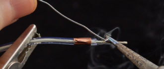
The most reliable way to connect wires is by welding. Wires should be welded from only one material, either only copper or only aluminum. The welding technology is simple, but the question arises in acquiring a welding machine and some experience in the work.
The wires are stripped of insulation, twisted, and then the end is cut off to equal length for each wire. And only then the end is welded. A small ball of molten metal forms at the end.
The exposed ends of the wires must be insulated with PPE insulating caps.
The welded connection is compact, reliable in operation and durable.
The connection easily fits into the junction box and does not lose contact when placed in it. Back to listing types of wire connections
4. Branch squeezes
Branch compression "Nut"
Branch clamps, otherwise called “Nuts”, allow you to make branches from the supporting core. Most often used outside the apartment and home due to the large working diameters of the wire.
To connect a branch to the carrier core, this core is stripped to a distance equal to the length of the metal plates, and the branch wire is also stripped. Both wires are placed in the grooves of the plates and tightened with screws.
Compress content
Similar compressions can be used to connect dissimilar wires, i.e.
copper and aluminum. Back to listing the types of wire connections
All other connections that are still used in everyday life and even in some places in production, namely: twisting, twisting followed by soldering , are not allowed according to modern rules of the Electrical Code.
Source: https://dela-v-dome.ru/electrika/soediniteli-provodov.html
Correct twisting of wires
The electrical circuit is located over the area of virtually the entire frame, providing the room with electricity for household and industrial appliances, depending on the purpose of the building.
Essentially, a cable is supplied from the central network, which is subsequently placed in the switchboard, from which several more come out, are routed to different ends of the room and connected to the distribution box, from where the final wires come out, ultimately connected to sockets, switches, etc. . Precisely in the distribution.
boxes create the largest number of connections, and sometimes a soldering iron, welding, or connectors are not used there, but wire twisting is used, which does not require special devices or tools, but only those things that virtually everyone has (knife, pliers).
:
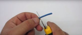
How to properly twist wires
In order to virtually reduce the possibility of short circuits and ignitions, the twists in distribution boxes must be made with high quality. If a person performs such an action for the first time, it is better to first carefully read the rules of such a connection, and only after that begin to perform the work. Let's figure out how to do twists correctly, what types there are, and what problems you may encounter when performing this work.
To begin with, it is worth saying that connecting two wires of different metals by twisting is not recommended. Many analytical articles and arguments have been written about this as to why this should not be done:
- different coefficients of thermal expansion (metals react differently to heating and cooling, as a result of which the contact gradually deteriorates);
- the appearance of an oxide film on the aluminum wire (it does not allow current to fully flow, the wire heats up and breaks down over time);
- structural destruction of aluminum during electrolysis (these two metals form a galvanic couple, and after exposure to a humid environment, the metal ends are subject to heating and subsequent destruction).
Twisting of copper and aluminum wires
Copper and aluminum cannot be connected directly to each other. However, in many houses there are aluminum wires that need to be connected to copper wires, and twisting is sometimes the only way to connect. In this case, it is important to adhere to certain rules that will allow such fastening to last as long as possible.
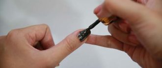
- To begin with, it is worth noting that the conductors must be tightly wrapped around each other. If their diameter is significant, there must be at least 3 turns, and if the diameter is up to 1 mm, in this case it will be necessary to wrap the wire around each other more than five times to ensure high-quality transmission of electrical flow. Also, after this it is very important to treat the bare surface with a special varnish that is resistant to water and moisture.
- When connecting copper and aluminum wires, it is better to use a special steel plate placed between them. This will avoid their direct contact. Thus, the service life of such a connection will be much longer. If you don’t have such a component at hand, then you can resort to treating the bare copper wiring with solder, which will also avoid mechanical contacts of these two metals.
- The ideal solution for connecting copper and aluminum conductors is to first apply solder to the copper core. Especially such pre-treatment is often used when connecting single- and multi-core wires, when in this way a wire consisting of several conductors is converted into a single-core one.
Twisting wires of different sections
This type of work implies the unambiguous use of additional means for connection. Such devices can be screw clamps, self-clamping terminals, bolts, tinned copper lugs, and walnut-type holes. Also, in order not to purchase additional components, you can use soldering or welding, or other methods of connecting wires.
If the difference in the diameter of the wires is insignificant, for example, 4 and 2.5 mm, then connecting them by twisting is not so difficult. To do this, you need to carefully wrap them around each other, after which you need to use welding or soldering. This fastening of two conductors will last for many years without complaints.
In other cases, twisting wires will not be reliable and durable. In such situations, you simply cannot do without additional components. In various situations, certain devices are used:
- if the cross-section of the wires is large, it is best to use a self-clamping terminal;
- for branching from the main line to the distribution. The shield uses a branch compressor, which among experts is also called “Nut”;
- To connect wires with a large diameter, a copper-tind tip is used.
Errors when twisting wires
The most common problem with connecting conductors in this way is that one wire wraps around another. This is completely wrong. The wires must evenly wrap around each other, thereby ensuring reliable passage of electric current and creating mechanical strength so that such fastening will last for many years.
The length of the twist depends directly on the diameter of the conductors themselves. It is worth considering that the minimum threshold for this characteristic should be no less than 3 cm. Otherwise, everything depends on the diameter of the wires: the larger the diameter, the greater the length of the created twist should be, but there are no specifically prescribed standards in this regard, Each specialist decides for himself what this value should be in order for the connection to be reliable and of high quality.
Source: https://uelektrika.ru/soedinenie-yelektroprovodki/pravilnaya-skrutka-provodov/
Piercing clamps for SIP wire. Characteristics, comparison tables. Connection errors
Branch piercing clamps, or as they are colloquially called SIP nuts, are the most important element of an electrical transmission line made of insulated wires. The reliability of your power supply and trouble-free operation of the entire VLI depend on them.
The contact in them must be constant and, most importantly, reliable throughout the entire service life of the power line, which is 40 years or more. If somewhere they use homemade hooks for hanging a line and this may not affect its reliability for years, then the connection of SIP wires and cables, SIP and SIP, should only be factory-made.
The two most common types of punctures are waterproof and sealed. All manufacturers have recently opted for sealed ones to modernize and develop their line.
In piercing clamps, contact is ensured by plates with pyramidal teeth and a calibrated breakaway head. The moment of failure varies from 9 to 20 Newton, depending on the brand of “nut” and the cross-section of the connected wires.
Two characteristics must be indicated on the body of each clamp - the cross-section of the main line and the cross-section of the branch. Moreover, these parameters can be in a wide range.
For example, sealed clamp SLIW54 16-120/6-50. The first inscription means a line from 16mm2 to 120mm2 inclusive. The second is the cross-section of the seal cable or SIP, which can be connected through this puncture. When choosing, it is better to buy nuts closest to the larger cross-sections of the wire to be connected in order to ensure better transition contact.
Most of these clamps can be used to connect a cable to a live SIP, since the stripping head and the bolt inside do not come into contact with the contact plate.
All clamps except the breakaway clamp have a second head, but it is only necessary for dismantling. Remember that all these punctures are considered one-time use. Do not confuse them with simple die clamps, which can be unscrewed and tightened at least a hundred times.
There are times when electricians try to reuse piercing clamps on the same or a different line. Although the first head is broken, they use the second one to tighten it.
Besides the fact that it is impossible to calculate the exact tightening torque without a torque wrench, for some reason everyone forgets about the deformation of the contact plate teeth after the first puncture. In the photo below, on the right are the teeth after a SIP puncture, on the left - without a puncture. Feel what is called the difference.
Their sharpness is no longer the same, and accordingly, some of them can simply crush the insulation rather than pass through it.
Therefore, according to technology, wherever there are piercing teeth, all these clamps are considered disposable!
So that manufacturers don’t advertise or talk. Precisely because of the teeth, and not because of the nut breaking.
Technical characteristics and brands of piercing clamps from the most famous manufacturers of SIP fittings:
If you need to make a branch with SIP wire from non-insulated bare wires, with a cross-section from A-16 to 70 or AC-16-70 or more, or vice versa, connect SIP to them, clamps of a different design are used.
On the main side they have the familiar plate that everyone is accustomed to, which is placed on the bare wire, and on the branch side there is a piercing plate. Here are their brands, characteristics and technical parameters:
If such transition punctures are not available, many electricians do it the old fashioned way - the end of the SIP wire that is connected to the bare main is simply stripped to 20-30 cm, and an ordinary twist-bandage is made.
This cannot be done due to the design of the SIP wires. Since the wire in it is multi-wire, moisture will gradually penetrate between the wires. Over time, to an increasingly greater length from the point of twisting, while worsening the insulation resistance of the entire line.
As a last resort, if there are no transitional sealed punctures, you can use die clamps with a protective casing. Remove the insulation from the SIP by 5 cm and connect it to the bare overhead line through a die. Then you put a sealed casing on top.
How are piercing clamps installed? When the main line is stretched, all the cores are in a tense state. In this state, it is difficult and often impossible to separate one of the wires from the common bundle simply by hand.
Never use a screwdriver for this, as sooner or later you will damage the insulation with the tip. For this purpose, plastic separating wedges are used.
One wedge is inserted between the two wires and after about 20 cm, another is installed between the same wires. In this way, the core is separated from the common bundle by 4-5 cm.
After this, you can safely mount the clamp, placing the main line in one direction and the tap in the other. Care should be taken to ensure that the wires are laid parallel, without distortion.
It is not recommended to use ordinary open-end wrenches for tightening.
When tightened, the sharp teeth press and pierce the SIP insulation. To prevent further oxidation at the puncture site, there is a special lubricant inside the clamp. It envelops the puncture, thereby closing the access of air.
The contact plates are equally suitable for both aluminum and copper conductors. We can say that this is the ideal junction between aluminum and copper.
Is it possible to remove piercing clamps from a SIP line? This is not recommended. Even if you need to permanently disconnect the tap, it is best to bite out the outgoing wire and leave the puncture in its place.
In this way, you will not break the seal of the cores and moisture will not be absorbed through the holes from the teeth and deteriorate the insulation.
As a last resort, if it is necessary to dismantle the piercing clamp from the SIP, the cut site should be immediately insulated with a special sealing tape.
With any branch, wire cuts appear, which must also be reliably sealed. To seal such terminations, protective caps are usually used.
The cap on the clamp can be built-in or removable. It is better to choose punctures with built-in ones. Since, being at a height, on a support it is not always convenient to take this cap out of a bag or pocket, and often it is completely lost.
Technical characteristics and nomenclature of insulating caps:
This cap is required.
If you do not use it, then the SIP will “suck” so much moisture over time that a small puddle may form in your accounting cabinet!
Here is a clear example of the lack of SIP sealing at the entrance to the house and its consequences:
Another important point when using piercings is that it is prohibited to connect more than one branch on one sealed piercing clamp, unless this is provided for by its design.
It would seem that you have two outgoing cables with a cross-section of 6mm2. If you twist them together or even insert them inside the clamp without twisting, then nothing prevents you from tightening the contact in this way. This technique is often used when connecting several lamps through one piercing clamp.
However, just the same contact over the entire area of the outgoing core will no longer be sufficient. Moreover, in this case the insulating rubber gasket will not be able to compress the wire from all sides. And accordingly, we are no longer talking about any tightness. Moisture will easily penetrate inside the puncture, flowing down the surface of the insulation of the two wires.
Another commonly used piercing clamp is a clamp with a separate bolt tightening function. Due to this, this clamp is considered reusable, but only from the point of view of connecting branches.
If you often have to connect and disconnect the input to the house or temporary objects from self-supporting insulated wires (welding stations, portable electrical installations), then this device is the only way to do this painlessly for the line itself.
Since in this case nothing happens to the puncture on the SIP, only the bolt that tightens the outgoing cable is unscrewed, which also does not have any teeth.
In this case, the insulation from the branch core must be removed by 1-2 cm. Another advantage of these clamps is their versatility. Through them you can connect not only the entrance to the house and street lighting, but also the grounding drains of the neutral conductor.
Here are their main manufacturers, technical data and characteristics:
You cannot connect or extend SIP wires with piercing clamps. Even if it is a short section of up to 25m, for example the entrance to a house. That is why they are called branch clamps, and not connecting terminals.
To connect the wires, it is necessary to use connecting sleeves for crimping. You can read in great detail about all the nuances and errors of working with them in the article “How to connect SIP wires to each other.”
Moreover, it is not recommended to use such punctures to connect the main SIP to the anchor support, even if there is no tension there.
Since the contact area in such a clamp is incommensurate with the cross-section of the main wire. And such a clamp, without consequences for itself and the connected wires, may not allow a full long-term load of 100 Amperes or more to pass through, not to mention the short circuit current.
Punctures with separate bolt tightening also have a shear head. It plays the role of a kind of “fuse”. Since the SIP wire is in a tense state and each core is subjected to longitudinal mechanical load, it is necessary to pierce the wire and plunge the teeth into the core itself just enough so as not to reduce the mechanical strength of the line by more than 20% .
Some brands of clamps, for example Sicam, have a so-called Turbo option. It facilitates and simplifies the installation process.
The entire installation is divided into two stages:
- separate installation on the line. Take the untwisted clamp, insert it into the main wire and tighten the nuts with one hand so that the clamp is fixed.
- while the second end remains divorced. Calmly install the branch into it and complete the installation process.
The main advantages of using sealed piercing clamps on SIP lines:
- ensuring the mechanical strength of the wire
- safety during installation and maintenance
- weather resistance
Source: https://domikelectrica.ru/prokalyvayushhie-zazhimy-dlya-provoda-sip/
Wire connections
Most electrical wiring damage occurs where a wire connects to one or more other wires. Such places are called connections.
Hidden connections
Some electricians make hidden connections to speed up and reduce the cost of work. Electrical wires are connected behind suspended ceilings, false panels, under plaster or screed. It is not right. If the contact in such a connection is then broken, it will not be possible to repair it without damaging the finish.
PUE 2.1.23. Connections and branches of wires and cables must be accessible for inspection and repair.
An example of a hidden connection. After repair, distribution boxes with wire connections will be hidden behind the suspended ceiling and will become inaccessible for inspection and repair.
Branch boxes.
Wires cannot be connected just anywhere. If the connection is somewhere along the route between the electrical panel and the outlet, it will be difficult to find and repair. Therefore, the PUE requires wire connections and wire branches from the main line to be made in special boxes that can be opened when repairing the wiring without damaging the finishing of the room. Electricians call connection and branch boxes in one word - junction box.
PUE 2.1.26. Connection and branching of wires and cables, with the exception of wires laid on insulating supports, must be carried out in junction and branch boxes , in insulating housings of connecting and branch clamps, in special niches of building structures, inside the housings of electrical installation products , devices and machines.
Junction boxes come in different shapes and designs, but all have covers and places for water wires.
Socket boxes
Sometimes you can come across such a mistake as installing a socket or switch directly into a niche in a building structure. This installation is extremely unreliable - after a while the socket will become loose and begin to fall out of the installation site.
There is another extreme - the socket is walled up in the wall along with the wire, leaving only holes for the plug. The socket is “tight”, but over time the mortar corrodes the metal parts and the contact in the socket is broken. Replacing such an outlet is a big problem.
Each installation product (socket, switch) must be installed in an installation box. Electricians call this box a socket box. It looks like a splitter box and differs in appearance only by the absence of a lid. But if you look closely, the socket box has special places for attaching a socket or switch.
Twists
It is often written on the Internet that twisted connections are prohibited. However, there is no explicit prohibition in the PUE:
PUE 2.1.21. Connection, branching and termination of wire and cable cores must be carried out using crimping, welding, soldering or clamping (screw, bolt, etc.) in accordance with current instructions approved in the prescribed manner.
That is, twisting as a method of connecting wires is simply not mentioned in the PUE. And there's a good reason for that. The quality of twisting greatly depends on the qualifications and conscientiousness of the electrician. Poor-quality twisting will quickly burn out.
And correctly made twists in household electrical wiring last for decades without failures or damage. But what does “correct” mean?
- When connecting by twisting, the wires must be single-core , made of the same metal ( copper is connected to copper , aluminum is connected to aluminum ).
- The length of the twist should be about 5 cm , more is possible. The wire strands are cleaned to a shine and evenly twisted, squeezing them together as tightly as possible.
- The load in the twisted line should be no more than 2 kW . For more powerful consumers, lay the line with a single piece of wire (cable) from the panel to the consumer. Or use other connection methods.
Of course, you can’t do twists like in the photo below. Options a) and c) - short twist, the wires cannot be compressed tightly. Option d) - loosely twisted wires, they have poor contact. Options b) and e) are not twists at all. The wires are connected at one point, the contact is very poor and will burn out after a while.
Do not twist stranded wires yet . They are soft, flexible and it will not be possible to securely press one wire to another.
Finally, do not twist copper wire with aluminum wire.
When moisture gets into the junction of these metals from the air, a chemical oxidation reaction begins, which quickly breaks the contact.
Clamp connection
Using PPE (Connecting Insulating Clamp, which looks like a colored cap that is screwed onto a wire connection) for wires of different sections, as well as for connecting a single-core wire with a stranded one. In fact, the same twist, not provided for by the PUE. (2.1.21). Although these PPEs are called clamps, they clamp weakly and do not provide reliable contact. Can be used when connecting lamps and similar low-power consumers.
Screw clamp of stranded wire without crimping or soldering. A wire that consists of many strands cannot be securely clamped under a screw. It will definitely weaken, individual veins will stick out in all directions. The result is a violation and burning of the contact. Or shorting the protruding wires with another wire.
Connection of copper and aluminum wires.
May be required for renovations in Soviet-built houses. Such connections can only be made through an intermediate contact made of steel or tinned copper.
The simplest and most reliable option is a bolt with a nut and 3 washers. The middle washer separates the copper and aluminum.
More modern - terminals with tinned contacts. Convenient for electricians, because connections are made quickly and easily. But such terminals do not like overloads - they can melt or catch fire!
Back: Wire selection.
Source: http://sm64.ru/wire_connections/
What clamps are suitable for connecting the VVG cable to the outgoing overhead line? — Website about
From a transformer substation or public step-down transformer, the power supply is distributed through overhead line (OHL) wires throughout the village where your private home is located. A branch (input) is made from the overhead line to a private house.
The route to the house can be done by air, the so-called “airlift”, or by a trench in the ground. The choice of the type of power supply branch to the house depends on the geodesy of the area and the distance of the house from the overhead power distribution lines.
, from the presence of forest plantations around the house, from the passage of underground utility routes near the house, etc.
But no matter what type of power supply branch to the house you choose, you have to connect the branch cable (connections) to the overhead line (OHL) wires. Let's look at this in more detail.
Important! The connection of the power supply branch to a private house from the overhead line must be done by specialists from the energy supply organization. However, it doesn’t hurt to understand what is being offered to you as a thrifty owner.
Connecting an air supply branch to a private home
The overhead power supply to the house is carried out with insulated SIP wires or electrical cables VVGng, AVVG, etc. on a supporting cable.
Overhead distribution lines can be made of bare wires 4×70+35 mm2 (designated VL) or insulated SIP wires 3×70+95+25 mm2 (designated VLI).
The overhead line connection should be made at the overhead line support closest to the house. If the nearest support from the house is more than 25 meters away, then you need to install your additional support at a distance of no more than 15 meters from the overhead line and no more than 10 meters from the house.
If the overhead line is laid on insulators, the connection and branching of the wires must be made directly at the insulators or on them. Connecting a branch with self-supporting SIP wires and electrical cables on a supporting cable are slightly different.
Connecting SIP wires to an overhead distribution line
SIP wires do not require supporting cables and are self-supporting. Connecting SIP wires to overhead lines can be divided into four stages.
- Secure the wires to the house with an anchor clamp;
- Stretch the wires between the house and the support;
- Secure the SIP wires to the support with an anchor clamp;
- Connect the branch wires to the overhead line wires.
Attaching SIP wires to the house
To fasten wires to load-bearing structures (walls, poles) using anchors or tension clamps. (Look at the photo)
This is essentially a wire clamp, with a loop for attaching to a hook. The hook is attached to the wall of the house or to a support pole. The entire process of connecting a branch to a house via an overhead line can be described as follows.
- Two hooks or anchor brackets are attached: one to the wall of the house and the second to the support post.
- Using a tension clamp, the wires are secured to a hook on the wall of the house.
- Using a roller pulley (roller block), the SIP wire is stretched between the house and the support to the desired tension.
- The end of the wire is secured in an anchor (tension) clamp with a loop.
- The loop is put on a hook mounted on a support. Instead of a hook, an anchor bracket can be used.
Important! The hooks for attaching the anchor clamps should be secured to the main structure of the house and not to the siding or stucco.
Connecting the SIP wire to the “bare” wires of the overhead line (OHL)
To connect the SIP wire to the bare wires of the overhead line (OHL), you will need a special outlet clamp to connect the SIP wire to the bare wires. Using these clamps, the SIP wires are connected to the overhead line.
Connecting SIP wire to insulated overhead line wires (VLI)
To connect the SIP wire to the insulated wires of the overhead distribution line (VLI), you will need a special piercing branch clamp to connect the SIP wire to the insulated wires. The piercing clamp does not require stripping the insulation of overhead line wires. With the help of such a clamp, SIP wires are easily connected to the overhead line.
Connecting the branch to the house with cables on a supporting cable
The steps for connecting the cable on the supporting cable are the same as for connecting SIP wires. Only between the house and the support is the supporting steel cable stretched. To attach the cable to the wall of the house and to the pole, anchors with loops for cables or tension couplings are used, which are attached to the anchors with coupling connecting strips (see photo).
The wires themselves are connected to the wires of the main line using special die clamps to bare wires or piercing clamps to insulated wires. And the cables are secured to the cable with cable banding straps.
I will dwell in more detail on attaching anchors to the wall of the house and to the pole.
Attaching anchors to the wall of the house and to the pole
Depending on the cross-section, and therefore the weight, of the wires (cable) used for the branch, several options are used for attaching anchors to a wall or support.
Bolt hook. It is screwed into a special dowel, which is driven into a pre-made hole in the wall or support. The hook should be screwed into the main structure of the house, not into the sheathing. Suitable for light branch cables. For wooden structures, a hook with a screw tip is used.
Fastening anchors with through bolted connections to the wall. These are more reliable fastenings of anchors to the wall (see figure A and B).
Fastening anchors to the wall using an opening T-shaped fastening. A hole is drilled in the wall. When closed, the T-bar is a straight bar. After inserting into the hole, the mount opens and is held against the wall by the upper bar of the mount. (See Figure C)
Fastening anchors to the pole with crimping clamps. This is the most reliable way to attach anchors to a support post. The figure clearly shows the girth fastening technology. I will only add that instead of corners and studs, you can use a metal strip with a welded hook for the anchor. (In the figure “Installing anchors on column girths”)
Connecting a branch cable to the house, descending into a trench along a support
When running a branch cable into a trench leading to the house, you need to protect the cable on a support with a metal pipe or metal casing. From the ground, the cable protection must end at a height of at least 2 meters.
- The connection of the branch cable with the distribution wires of the overhead line must be done by soldering, using heat-shrinkable tubes for insulation, and the place where the insulation is removed must be protected with a special heat-shrinkable glove.
Sometimes you have to make a turn when the power supply branches to the house. The figure below shows the rotary connection of SIP wires or cables on a supporting cable.
Elesant.ru
Source: https://orensbyt.ru/osveshhenie/kakie-zazhimy-podojdut-dlya-prisoedineniya-vvg-kabelya-k-othodyashhej-vozdushnoj-linii.html