How to properly weld with inverter welding for beginners: alternating and direct current, cable cross-section
If you are going to do welding work yourself and decide to do it using an inverter machine, you need to understand in advance how to work with a welding inverter.
Then read this article: everything written here will be useful to you.
Preparing, purchasing, stocking up
The most important thing is to know that everything will work out perfectly, because inverter welding technology is very easy to learn and use; experience and skill are not particularly needed here.
Safety precautions
Any welding activity, including an inverter, is directly related to electrical current.
These rules are simple and straightforward:
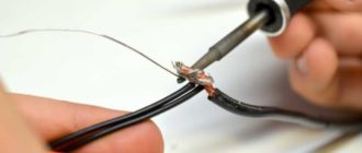
- It is necessary to check the cables for integrity and serviceability before connecting to the inverter. It is important to remember: the return cable with a clothespin goes to the negative pole. We attach the cable, where there is an electrical holder, to the positive connector.
- After a visual check, set the current control knob to the minimum value. Then we connect the device to the network. We listen to the operation of the fan when it turns on: if the noise is smooth and without crackling, everything is in order.
- Now let's take into account the considerable weight of the metal with which you will have to work.
Workwear
First of all, you need to take into account the effect of high temperature and have the following items:
- welder's mask with special light filters;
- protective gloves or gaiter;
- suit made of protective fabric;
- shoes with rubber soles;
- if necessary, a respirator if welding takes place in a closed room without ventilation.
Equipment
List of required equipment:
- inverter welding machine;
- hammer;
- electrodes selected for the type of work, taking into account the nature and thickness of the metal;
- metal bristle brush
Let's start cooking
First we set the correct current strength on the inverter. We remember that in inverter technologies, alternating current welding is the main type. The strength of the welding current depends on the composition of the electrode and the diameter of its tip, the position of the workpieces during welding and the type of seam in the planned joint.
All these dependencies can be found in the comprehensive instructions for the device itself and in the inserts in packs of electrodes. Theoretically, the welding current can be selected according to the diameter of the electrode rod: for each millimeter of diameter there should be about 30 A.
We find a comfortable and stable position, put on a mask and begin work with the elbow abducted. It is better to wrap the forearm with a cable. If this is not done, your hand may get tired during welding, and the cable will begin to dangle, which will negatively affect the quality of the weld.
Direction of electrode movement for a novice welder.
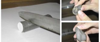
For debut work, it is better to choose metal blanks that are not the smallest size - more than 20 cm, this will be more convenient. As beginners usually do: put on a mask, ignite an electric arc and immediately, with one breath, pass the workpiece along the entire length of the seam.
If your part is short and you weld it in one breath, you may develop the unnecessary habit of welding the seam in one breath. Therefore, train on long parts with proper breathing.
Now about the arrangement of objects during work. It is better to place the workpieces on a work table - a horizontal surface. The electrode in the holder should be at right angles to the table plane, then the angle of inclination should be approximately 30°.
Now you need to ignite the arc to move along the planned weld.
It must be remembered that when burning, the electrode shortens, so the distance above the surface must be constantly monitored.
Now about the arc and electrodes
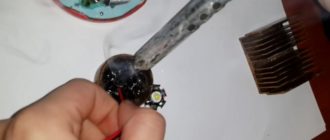
Quickly igniting and holding the arc correctly is perhaps the most important thing for successful welding with an inverter. The arc should not be interrupted - this is what you need to watch out for when the electrode approaches the workpiece plane.
In this case, you should tap the electrodes longer so that the film breaks. The relationship between welding current and electrode diameter can be easily calculated using tables that are available in large numbers on the Internet.
Functional diagram of welding with an inverter.
If you have an advanced inverter model, then it is equipped with additional functions that make life easier for beginners and everyone else.
These advanced features are:
- The Hot Start or HotStart function makes it easier to ignite the electric arc.
- Anti-sticking or arc forcing is activated when the electrode approaches the metal surface too quickly. This function increases the current level.
- Antistick or AntiStick, on the contrary, turns off the current to prevent overheating of the welding machine.
It is better to learn from the simplest form of seam - a thread seam, for which the electrode must be guided evenly without any oscillatory movements.
Once you start to feel comfortable with the thread technology, you can start welding metals with oscillating movements in different configurations - there are several of them.
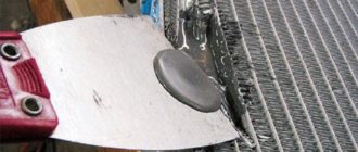
In such cases, you need to make the first few oscillatory movements to form a weld pool. We tilt the electrode at an angle of 30°, no more and no less. Once the pass is completed, you need to beat off the slag crust with a hammer to clean the new seam using a wire brush.
In order for the seam to come out high-quality and aesthetically pleasing, at the end you should make a couple of oscillatory movements towards the metal surfacing. In this way, crater formation can be avoided.
About welding seams
The seams that are formed using inverter welding are as follows:
- single-pass, in which the thickness of the metal workpiece is replenished in one pass;
- multi-pass, in which one pass of electrodes is not enough. Used when welding thick edges.
The most famous and simple way to check the quality of a seam after welding is to tap it with a hammer. At the same time, the slag layer bounces off - provided that the seam is even and smooth. Also, the quality of the seam depends on the temperature: it must be correct.
If the seam is overheated, it may break; if the heating is insufficient, a very unpleasant thing will happen - lack of penetration.
Polarity forward and reverse: what is the difference
Polarity in welding on an inverter machine is an extremely important thing that you need to understand.
At its core, polarity is the direction of electron flow, which depends on the order in which the cables are connected to two different connectors on the device. Inverters have the ability to select the type of polarity. The welding current can also be adjusted.
Reverse polarity
Types of polarity for welding.
This is the negative pole on the metal workpiece, and the positive pole on the electrode. The current thus moves from minus to plus, that is, from the metal to the electrode. With this method, the electrode gets quite hot. The method is good when welding thin metals as the risk of burn-through is reduced.
Straight polarity
Here it’s the other way around: the negative pole is on the electrode, and the positive pole is on the metal of the workpiece. The current now flows from the electrode to the part being welded, which in this case heats up more than the electrode. This is how they work with thick metal edges.
It should be noted that the polarity is always indicated in the instructions on the packs of electrodes.
One of the main “inverter” questions from debutants is what is the most optimal polarity when welding with an inverter? The answer depends on many criteria, but from the point of view of cutting metal, the polarity should be straight.
The fact is that with this type of polarity, the molten area turns out to be deep and narrow - just what is needed when cutting.
With reverse polarity, the opposite is true: the melting zone is shallow and quite wide.
Cook, cut
If you are working with thin sheets of metal, you need to choose the right small diameter electrode and welding current. If, for example, the edge thickness of your part is 0.8 mm, the diameter of the electrodes should be 1.8 mm. Well, the welding current should reach 35 A. You need to cook using intermittent movements.
The question of which electrodes to weld with is decided taking into account the type of welding and the nature of the metal.
We ignite the electrode and place it exactly at the location of the planned hole. Press for good heating. We rearrange the electrode, press and heat again. And so on until a hole of the desired shape and size is cut.
If you are cutting sheet metal, the sheet must be fixed vertically. In this case, drops of molten metal will flow down, otherwise you risk getting frozen metal icicles at the bottom of the cut.
To be honest, all cutting of metals with a welding machine, even with the most advanced inverter, is not the best idea from a technical point of view. There is always a risk of metal melting at the cut site - the metal can simply melt out. The best way to cut metal is with a grinder.
We choose, we buy
Table of characteristics for welding with an inverter.
It would be useful to google and read about domestic and foreign manufacturers whose products are offered on the Russian market. These are mainly European and Asian countries.
Equipment from Asia is usually inexpensive and of very decent quality, with the exception, of course, of handicraft fakes.
European inverters are distinguished by qualities with the obligatory adjective “high” in front: high price, high reliability, high quality. There are few Russian devices on the market.
Understand the brand of welding cable and its cross-sectional area. The right choice will help you avoid difficulties with power surges if they occur during welding.
The second thing to do is figure out the availability of service centers around the country. If you live in a city with a population of one million, a service center for a specific product is unlikely to be a problem for you. But if you live in a remote region, this issue will become one of the most important for you.
But the main thing is protection from ultraviolet radiation from a hot arc. The most primitive option is a mask made of plastic and a light filter, which is selected depending on the current strength, lighting and your vision.
A more expensive and much more comfortable option is a mask with a Chameleon-type light filter, which automatically changes its characteristics and can be adjusted to suit the ambient light and the condition of your eyes.
There are many tables on the Internet with data that will help you choose the right filters. It is better to choose them for a number larger or smaller. The best solution would be to check the lighting in the work area and your vision.
Okay, we agree, you don’t have to buy a whole suit made of special fabric. But a canvas apron with gloves is not a whim, but your protection. It is better to choose mittens from split leather. Pay attention to your shoes: be aware that drops of molten metal may fall on your feet.
How to care for the inverter?
Any equipment loves care and order, your inverter is by no means an exception. The rules on how to properly cook using inverter welding and how to store it correctly are simple.
Selecting an electrode for welding various metals.
Before work you need to do the following:
- carry out a visual inspection of the device and prepare the place where you are going to work;
- install the inverter in a horizontal position with the desired protection from dust, precipitation and other contaminants;
- connect the cable to the connectors in accordance with your plans, usually this is plus to the electrode and minus to the metal;
- connect power supply. The most important nuance: if you use an extension cord, the cross-section of the welding cable must be at least 2.5 mm².
- ignite the arc at separation as a test test;
- make sure the casing is intact, because cooking without it is strictly prohibited;
- adjust the current mode. You can start cooking.
You must store your device according to the following rules:
- Constantly check all components of the device. The frequency of checks depends on the intensity of use of the device and the degree of dust in the work area;
- Clean the device from dust using compressed air and low pressure. Do not clean the electric plateau with a jet of air, but use a soft brush;
- check the strength of power connectors, the integrity of the plug, socket and insulating coating of electrical cables;
- It is better to store the inverter in dry conditions, the air temperature should be within the range from -15°C to +50°C, the optimal air humidity is about 70 - 80%.
- Remember to disconnect the inverter from the network when it is not working.
Source: https://tutsvarka.ru/vidy/kak-pravilno-varit-invertornoj-svarkoj
How to properly set up a semi-automatic welding machine: setting table
The saturation of home workshops with complex professional-level power tools is impressive. But not all of the equipment's rated capabilities are used. How to set up a semi-automatic welding machine for metal of different sections, change it to aluminum, stainless steel - dry information in the instructions is not enough. Let's turn to the knowledge of production workers.
External influence on settings
Changing the spatial position of the seam, strengthening the leg, thickness, and configuration of the joints of one metal will require different settings. Basic settings of a semi-automatic machine (PA):
- Arc voltage; the adjustment is reflected in the change in current value.
- Current – wire feed; An increase in wire feed speed is responded to by a proportional increase in the current value and vice versa.
- Gas consumption is set based on the main parameters and is regulated by assessing the quality of the seam while excluding pore formation.
Further, based on the results of the test pass, the modes of electric arc welding in a shielding gas environment are adjusted.
For an experienced practitioner, even the sound of a lit arc is informative. Once you purchase a semi-automatic machine, you will have to get used to its features and the need to adjust to changes:
- The configuration and assembly of PAs with equivalent characteristics differ in their filling; differences in configuration are found among the same manufacturer.
- Voltage fluctuations disrupt settings; the transformer PA will turn off, and the inverter may burn out.
- Changing the composition of the shielding gas.
- Changing the brand and diameter of the wire.
- Even minor repairs or replacement of components will have an impact.
Gas protection
Gas flow also refers to calculated tabular values . Does not directly affect the settings of the semi-automatic welding machine. Control is simplified if the gearbox is equipped with 2 scales. Registration of the reduced flow value is perceived more objectively with the installation of a rotameter.
The rotametric flow meter shows the supply of carbon dioxide (argon) working pressure in constant values. The static pressure reading will drop when the burner trigger is triggered, creating a protective cloud. The initial range for the rotameter is 6–10 l/min, for a gearbox with pressure gauges – 1–2 atm.
Economical consumption is selected according to the porosity of the seam: the gas flow increases until the pores disappear . In a room with forced exhaust and in the wind, in order to save money, it is preferable to use cored self-protecting wire.
Selection of gas mixture
The choice of mixture is determined by the quality requirements and material properties:
- CO2 is an ideal protection for the weld pool of structural steels, deep penetration, but the spattering and roughness of the weld are not suitable for fine work.
- A mixture of argon and carbon dioxide C25 (75% Ar; 25% CO2) - the combination is suitable for welding thin-sheet structures, creating a uniform seam with a minimum of splashes.
- Composition of 98% Ar; 2% CO2 – for stainless steels.
- For aluminum – argon in its pure form.
Voltage setting
The power consumption for burning the arc and melting the metal is determined by the voltage setting. Energy consumption increases with increasing penetration depth (material thickness) and wire diameter.
The settings of household PAs are stepped. Coarsening with min/max modes or multi-mode, with soft adjustment as an extended range of adjustment of the welding voltage of the Wester MIG-110i semi-automatic machine for 10 settings.
On the inside of the casing cover there is a table of regulations for voltage settings . This is the manufacturer’s main hint; it is printed on models that differ in power and technical equipment.
The final solution is how to set up a semi-automatic welding machine for the operator. Vague recommendations are not dogma, the main criterion is the depth of penetration and the strength of the connection.
Wire feed speed
The wire feed speed controller controls the current intensity . The feed amount is one of the main variable characteristics. Set after voltage selection: the melting speed determines the movement of the electrode in the burner.
This value is subject to adjustment after changing the brand and diameter of the wire, changing the voltage. There are PAs with automatic mode adjustment, but they are in the segment of expensive equipment.
Fine-tuning the movement of consumables to optimize adjustments is desirable . Excessive acceleration will lead to sagging, deceleration will lead to subsidence, waviness, and seam breaks. The balance of current and voltage, controlled by the feed rate, adds up to an optimal roller.
The first indicator of a mode discrepancy is revealed in action - the feed speed with the ignited arc decreases, but the wire does not have time to melt, bends, sticks to the workpiece, and active spatter occurs.
Insufficient supply - the inverter electrode burns out before touching, the tip becomes clogged. Selecting the speed/current mode for the set voltage is the first step towards professionalism .
Wire feed speeds in a semi-automatic machine, a table of the direct relationship of the effect of changing settings on the final result:
Polarity
The procedure for changing polarity is simple. Under the cover there is a sign indicating which type of metal and wire require direct or reverse polarity. Direct - the burner is connected to the minus terminal. With straight polarity, the melting of the wire is accelerated by 50%, but the stability of the arc decreases.
Welding with self-shielding flux-cored wire is carried out with straight polarity . The maximum heat generation energy is spent on protecting the seam. The flux will react without any residue. The tendency to splash is compensated by indifference to under-cleaning of work areas and gusts of wind. Costs in the form of splashes and slag crusts are a necessary evil.
A solid copper plate in a gas cloud is connected to the positive terminal . Preparing material for welding involves cleaning up signs of corrosion, contamination of joints, and cutting. Conductivity increases with increasing diameter. For large cross-section workpieces, there is a reason to increase the wire cross-section.
Wire ejection and release
The length of the consumable electrode extending from the contact tube (tip) and the size of the working gap of the torch affect the quality of the permanent connection.
The relative position of the burner tip relative to the nozzle varies in individual designs. They are located at the same level, the contact tube is recessed or extended relative to the nozzle up to 3.2 mm.
At a short reach, welding of structural low-alloy steels is carried out - increasing the distance thins the cover with protective gas. The flux-cored wire is artificially lengthened to increase the melting point .
Arc setting
Already simple PA models have a vernier control over inductance values . Setting the hardness changes the temperature of the arc and the depth of penetration with a noticeable convexity of the seam. Parts are sensitive to overheating and thin walls no longer interfere with welding.
Reducing the compression of the current channel (increasing inductance) raises the melting temperature, the penetration is deep, and the weld pool liquefies. The seam bead is flattened. Controlling the penetration depth, arc and bath temperature is a qualitatively new level of setting up a semi-automatic welding machine.
Small diameters of the additive make the arc more stable, the deposition rate increases, the penetration depth is optimized, and spatter is reduced. Based on the convexity of the seam and the amount of spattering, the length of the arc is specified: a short one gives a volumetric seam, a long one interferes with the concentration of the melt .
| Inductance max | Inductance min |
| The penetration deepens | Low temperature arc |
| Weld pool liquefaction | Splashing increased |
| The seam bead is even and smooth | Volumetric seam bead |
| Corner, reinforced seams | Setting up a semi-automatic machine for welding thin metal |
Wire feed speed control
The wire feed activation switch can be two-position (High/Low) or multi-stage. Larger diameter solder is dispensed at a slower rate, optimizing the process.
Before starting work
When the PA is prepared for work according to the instructions, it is worth spending time clarifying the configuration modes. To help, we offer a table as a guide. Drawing up an analogue with the individual properties of PA will help in determining the best modes and clarifying the capabilities of the technique .
The own table of welding current for a semi-automatic machine tends to grow with new material and welding conditions. It won't hurt to check the position of the switch on paper to help you remember.
The recommended voltage is selected. By manipulating the current strength and the additive supply rate, we select the optimum with a decrease in current and a maximum supply. Then, as the amperage increases. The voltage changes every 0.5 A. The detailed table will become your personal speed adjustment instructions .
Indicative table: welding current (wire feed speed), interdependence of process components:
The influence of stress on the quality of the seam
A convex weld with sufficient penetration without porosity, sagging and undercuts will only be produced when the main component - stress - is balanced with the accompanying ones.
Low settings produce a tapered high seam with little penetration. High – flattened with spreading and deep crater of the bath. Excessive voltage has a negative effect on weld formation : it is not possible to create a bead of sufficient volume when the melt depth is on the verge of burning through.
In the photo above:
- the calorific value of the voltage is optimal;
- insufficient;
- redundant.
Possible problems and errors
Problems and mistakes when blindly following average recommendations are the fault of the welder. This was mentioned above. Selecting a welding mode is a delicate matter. Creativity and attention to detail are half the way to success .
Relying on the experience of a professional will help:
- Crackling or clicking sounds are a signal of insufficient solder supply speed.
- The additive melts further away, up to the tip - the feed rate is reduced.
- Excessive spatter - increase gas supply and inductance.
- Porosity, shades of brown and green on the seam – poor gas protection.
- Burning, lack of fusion - too much or too little voltage, adjust the inductance.
- Unevenness of the seam, instability of the arc, lack of penetration - contamination of the welding field, loose clamp of the mass.
- Variability of the fullness of the bead, notches - the speed of the torch and the position relative to the seam are disturbed.
- The seam is interrupted, uncontrolled spattering - the arc length has been exceeded.
Source: https://svarka.guru/oborudovanie/vidy-apparatov/kak-pravilno-nastroit-poluavtomat.html
Manual arc welding mode parameters: current, electrode diameter, welding speed, etc.
The set of factors that influence the quality of the resulting seam and ensure stable progress of the welding process are called welding mode parameters.
When performing manual arc welding, the following welding mode parameters are distinguished:
- electrode diameter;
- welding current strength;
- type and brand of electrode;
- arc voltage;
- type of current and polarity;
- welding speed;
- location of the seam in space;
- heating and heat treatment;
- ambient temperature.
The last three parameters are considered additional, the rest are basic for this type of welding.
Electrode diameter
Which electrode diameter to choose depends on the thickness of the metal being welded, the position in which the welding will be performed, the type of connection, the size of the part and the chemical composition of the metal.
Table 1. Ratio of metal thickness and required electrode diameter| Metal thickness, mm | 1-2 | 3 | 4-5 | 6-8 | 9-12 | 13-15 | 16 and over |
| Electrode diameter, mm | 1,5-2 | 3 | 3-4 | 4 | 4-5 | 5 | 6 |
During welding, in all positions except the bottom, liquid metal drips down. Therefore, for welding in a vertical, horizontal and ceiling position, regardless of the thickness of the metal, you cannot use electrodes with a diameter of more than 4 mm. Thick-diameter electrodes form a large drop of liquid metal, which the force of surface tension cannot cope with.
For the root of the weld in multilayer welding, electrodes with a diameter of 3-4 mm are used; subsequent layers can be performed with electrodes of a larger diameter.
Current strength
The current strength is set after selecting the electrode depending on its diameter. To calculate the welding current when welding in the lower position, there is a formula:
Ist = delK
where Ist is the current strength, A; K - proportionality coefficient (changes its value depending on the type and diameter of the electrode).
Table 2. The value of the proportionality coefficient depending on the diameter of the electrode| Electrode diameter, mm | 1-2 | 3-4 | 5-6 |
| Proportionality coefficient (K), A/mm | 25-30 | 30-45 | 45-60 |
You can use a simplified formula for selecting welding current for manual arc welding:
Ist = (20 + 6 div)div
In order to avoid waste when welding in the lower position of metal with a thickness of less than 1.5 divisions, the welding current is reduced by 10-15% of the calculated one. If the metal thickness is more than 3 div, the current is set to 10-15% more.
When welding seams in a vertical position, the current is reduced by 10-15%, and in the ceiling by 15-20% of that selected for welding in the lower position.
If welding work is performed with high-quality, certified electrodes, the current strength should be set in accordance with that recommended on the packaging with the electrodes. The calculations above can be used in the absence of recommendations from the manufacturer as an alternative method.
Once the amperage is selected, the welder must place several beads on a separate plate of metal. In this case, the width of the seam and the depth of penetration are assessed. If necessary, the current strength is additionally adjusted.
Too small current modes lead to unstable combustion of the welding arc. Lack of penetration appears in the welded joint, and labor productivity decreases.
Increased current values are accompanied by its overheating, high combustion rate, lack of fusion, intense metal spattering and deterioration in the appearance of the seam.
A balanced current strength is characterized by a moderate melting rate of the electrode, stable arc burning with insignificant metal spattering.
Electrode type and brand
First of all, it is necessary to select electrodes that ensure uniformity of the chemical composition of the base metal and the metal rod of the electrode. Also, the type and brand are selected depending on the spatial position of the seam, the required density of the seam, ambient temperature, strength of the product and operating conditions of the structure. Using an electrode, you can give the seam the necessary properties.
Arc voltage
The welder can adjust the arc voltage by changing the length of the welding arc. Depending on the arc length in manual arc welding, the voltage is in the range of 16-40 V.
According to welding technology, the voltage should be kept at 16-20 V. For this, welding is usually performed with a short arc measuring 0.5 -1 thickness of the electrode diameter. This value may vary depending on the brand of electrode and the position of the seam in space.
Type and polarity of current
AC welding is used to join low-carbon and low-alloy steels (type 09GS) in construction and installation conditions with rutile-coated electrodes. For welding thick structures made of low-carbon steels. If magnetic blast occurs during welding with direct current sources.
DC welding can be divided into two processes - manual arc welding with direct and reverse polarity.
On straight polarity
Direct polarity is used for welding cast iron and deep penetration of the base metal. For welding low-, medium-carbon and low-alloy steels with a thickness of 5 mm or more using electrodes with calcium fluoride coating: UONI-13/45, UONI-13/55, etc.
On reverse polarity
Reverse polarity is used for welding sheet metal of low thickness and welding with an increased melting rate of the electrode. For welding low-carbon steels (type 16G2AF), low-, medium- and high-alloy steels and alloys.
To indicate a certain type of current, the designations AC and DC are often used today.
The abbreviations AC and DC (short for alternative current and direct current) mean alternating and direct current, respectively.
The welding speed is selected by the welder depending on the properties of the base metal, the characteristics of the electrode, the position of the seam, etc.
The welding speed should be such that the liquid metal of the weld pool rises slightly above the surface of the base metal with a smooth transition to it without undercuts or sagging.
To prevent overheating of the metal, high-alloy steels are welded at a higher speed.
Seam location in space
The location of the seam in space affects the choice of the main parameters of the manual arc welding mode. Manual welding is used for joints in all spatial positions, but the bottom position is considered the most convenient. It is worth considering the position of the seam in space when calculating the main parameters and choosing an electrode.
Preheating and post-heat treatment
Preheating of the base metal and subsequent processing are used for welding steels prone to the formation of hardening structures - medium and high carbon steels. For welding cast iron, non-ferrous metals and their alloys. The temperature and method of heating and processing depends on the thickness of the base metal, chemical composition and size of the structure.
Ambient temperature
All steels can be divided into four groups according to the degree of their weldability. Steels of groups II, III and IV cannot be welded at temperatures below -5 °C.
Source: http://osvarke.net/mma/rezhimy-ruchnoj-dugovoj-svarki/
Installing a submersible pump in a well with your own hands - Metals, equipment, instructions
Now the work on drilling a water well has been completed, the siege column has been installed, and the well has been washed and ready for operation.
For uninterrupted operation of the source, all that remains is to select pumping equipment for the well and install the pump according to all the rules.
We will discuss below how to do this correctly with your own hands and how to smoothly start a deep-seated unit. And for example, look at the video located in the material.
Points to consider
When choosing a borehole submersible pump, give preference to centrifugal models. They have a less destructive effect on the walls of the well shaft, unlike vibration pumps
Before installing the selected well pump into the casing and starting it smoothly, it is important to consider several points that will make the pump even more efficient:
- So, whatever the immersion depth of your unit, you should choose a submersible pump model that is equipped with protection against dry running. Thanks to such a system, even a sharp and critical drop in the water level in the well will not in any way affect the performance of the equipment. Dry running protection will work instantly and protect the pump from combustion.
- An important point is not only protection against dry running, but also the diameter of the unit itself. The recommended gap between the walls of the casing pipe and the walls of the pump body should be 4 mm. If there are more, then even better.
- When choosing a borehole submersible pump, give preference to centrifugal models. They have a less destructive effect on the walls of the well shaft, unlike vibration pumps. In addition, the use of a vibration unit, even with protection against dry running and a check valve, is not recommended, especially for sand wells. There is a risk of loosening the sandy bottom.
- And it wouldn’t hurt to take into account the pump’s performance for high-quality and uninterrupted water lifting. To do this, you need to calculate the average amount of water consumed per family per day.
Complete set of tools and working elements
Before lowering a pipe already connected to the pump into the well, it is advisable to level it by securely fixing it in the area
In order to correctly and reliably install a deep submersible pump in a water well, you need to stock up on the following items and components:
- Pump of the selected model;
- Water intake pipe in the form of a PVC hose of the required length and diameter;
- Electrical cable;
- Safety cable (preferably made of stainless steel) of the required length;
- Check valve;
- Plastic fitting for connecting the pump to the water intake pipe;
- Adjustable wrenches;
- Plumbing tape FUM or Tangit (winding).
Important: before lowering a pipe already connected to the pump into the well, it is advisable to level it by securely fixing it in the area. That is, stretch the desired section of pipe across the area and secure it with bricks or other heavy objects. But avoid damaging the PVC.
Installation steps for a submersible pump
First of all, you need to attach a check valve to the outlet pipe of the pump.
The installation diagram of the unit in a water well will be as follows:
- First of all, you need to attach a check valve to the pump outlet. It is important to install it so that the arrow drawn on it faces up. We wrap all threaded connections with tape and securely clamp them with an adjustable wrench.
- Now it's time to install the adapter-fitting for the pipe. It is this that will allow you to attach a submersible well pump to the water intake pipe.
Important: installation of the fitting must be done in two stages. First we attach its smaller (lower) part. To do this, we tightly wrap the plumbing tape and fix the thread of the fitting to the thread of the check valve. We clamp everything well with keys. In this case, an additional layer of sealant can be used at the junction of plastic and metal.
- Insert the water inlet pipe into the existing hole with a rubber seal until it stops. In this case, first, not its base, we will put on the second part of the fitting with the thread towards the joint. After the pipe is inserted into the front part of the connecting element, we bring its second part along the pipe and securely join it using a thread.
Installation of safety hummock and cable
We connect the electrical cable and the water intake pipe together using the tying method
Now we proceed to fastening and installing the safety rope and electrical cable according to the further scheme.
And if everything is clear with the wire (it is connected to the pump), then the safety cable, selected in accordance with the parameters of the well, is attached to the base of the pump and secured with special steel clamps.
In this case, the clamps themselves and the end of the steel cable must be insulated with special adhesive tape (insulating tape).
We connect the electrical cable and the water intake pipe together with our own hands using the tying method. To do this, you can use plastic clamps or just electrical tape.
It is important to avoid putting too much tension on the cable or letting it sag. This method of installing the wire and pipe will prevent the formation of a loop around the pump during its operation.
And this, in turn, will protect against jamming of the pump in the well when it is lifted.
We fasten the safety cable to the pipe and cable in the same way with clamps. It can be fastened with a simple duct tape tie with a large pitch.
Lowering the pump into the well
In order to hermetically close the wellhead, you need to cut off the upper part of the casing, which has a thread. Since this particular section is wider in relation to the rest of the column
- And the last stage of installing a well pump on water with your own hands according to the diagram is installing a pipe into the hole in the head. In order to hermetically close the wellhead, you need to cut off the upper part of the casing, which has a thread. Since this particular section is wider in relation to the rest of the column.
- Having cut the thread, we disassemble the head into two parts and put the lower one on the pipe. At the top you need to lay a dense rubber layer.
- We thread a water intake pipe into the hole in the upper part of the head, and pass the cable and cable through special bolts located on the inside of the cover.
- We slowly and carefully lower the pump into the well and carry out its smooth start. Water should flow out of the pipe with sufficient pressure.
- We install the upper part of the head and securely fix it with bolts.
- After the well pump has been mounted and smoothly started, all that remains is to connect the water inlet pipe to the individual water supply system.
- The minimum distance from the pump to the bottom of the well should be 1 meter. And the minimum immersion depth of the unit is 0.5 meters.
Source: https://spb-metalloobrabotka.com/elektrody-dlya-svarki-postoyannym-tokom-kakie-luchshe/
Selection of welding current depending on the diameter of the electrode | Welding and Control
The welding mode is understood as a group of controlled parameters that determine its conditions. The welding mode parameters are divided into basic and additional.
The main parameters of the manual welding mode include current strength, type and polarity of current, arc voltage, electrode diameter and welding speed. Additional parameters include the composition and thickness of the electrode coatings, the position of the electrode and the position of the product during welding.
The most important and primary stage in determining welding modes is the selection of the diameter of the electrodes. The diameter of the electrode is selected depending on the thickness of the metal and the spatial position of the weld and the type of connection.
The approximate relationship between the metal thickness S and the diameter of the electrode when welding a seam is given in the table below. The spatial position in which electrodes can be cooked is indicated on the pack.
For more information about the designation of the characteristics of electrodes and their decoding, read the article Coated electrodes, characteristics, technical requirements. Classification, marking GOST 9466-75
Vertical, horizontal and ceiling welds, regardless of the thickness of the metal, are welded with an electrode diameter of usually 3 mm to a maximum of 4 mm in order to avoid drainage of liquid metal and slag from the weld pool.
Also, the root of the seam is made with electrodes with a diameter of no more than 3 mm, to ensure complete penetration, and subsequent layers of the seam are made with electrodes of a larger diameter.
Setting the current depending on the diameter of the electrode
The strength of the welding current is selected depending on the brand and diameter of the electrode, taking into account the position of the seam in space, the type of connection, the thickness and chemical composition of the metal being welded, as well as the ambient temperature.
Welding current is one of the main parameters of the welding process, on which the quality and reliability of the resulting weld depends.
When taking into account all these factors, it is necessary to strive to work at the optimal possible current strength to ensure a stable welding process.
Important: Welding current and electrode diameter are interrelated.
The choice of welding current must be approached responsibly!
Incorrectly selected welding current will lead to defects. If the current is too high, the welded parts will burn through. If the welding current is insufficient, the metal will not melt, resulting in lack of penetration and lack of fusion. There is nothing complicated in choosing a welding current.
Recommendations for choosing the current strength can be found on the pack of electrodes or in reference books and regulatory documents. Recommended average welding current values are given in the table below.
Depending on the spatial position of the weld, the current value must be adjusted, so for welding vertical and ceiling seams, the current strength is reduced by 10-15%. It should not be forgotten that for these welding positions the electrode diameter should not exceed 4 millimeters.
If you follow these rules, the welding process will proceed steadily and the metal will not drain from the weld pool. Read more about welding techniques in various spatial positions in the article: Manual arc welding technique with coated electrodes
The welding arc voltage on the machines is set automatically, so we do not consider this parameter
The strength of the welding current is determined by the formula
Isv = πde2 * j / 4,
where de is the diameter of the electrode (electrode rod), mm;
j is the permissible current density, A/mm2.
With approximate calculations, the value of the welding current can be determined using one of the following formulas:
Iсв=k*de
Isv=k1*de1.5
Isv=de*(k2+α*de)
where de is the diameter of the electrode (electrode rod), mm;
k1, k2, α - coefficients determined experimentally:
k1=2025; k2=20; α=6.
Recommendations for choosing the current strength can be found on the pack of electrodes or in reference books and regulatory documents.
Recommended welding current values for electrodes of various diameters
Source: https://svarkka.ru/%D0%BF%D0%BE%D0%B4%D0%B1%D0%BE%D1%80-%D1%81%D0%B8%D0%BB%D1% 8B-%D1%82%D0%BE%D0%BA%D0%B0-%D0%B8-%D0%B4%D0%B8%D0%B0%D0%BC%D0%B5%D1%82%D1 %80%D0%B0-%D1%8D%D0%BB%D0%B5%D0%BA%D1%82%D1%80%D0%BE%D0%B4%D0%B0/
Starting current of welding inverter
Inverters, or they are also called converters, are popular welding machines that are powered by autonomous generators (power plants) produced by manufacturers in a wide range.
Which generator is suitable for welding? What criteria or parameters should I pay attention to when selecting a generator model? How to competently and correctly select it? The reader will receive answers in this article.
The generator for the welding inverter is selected based on a very important characteristic of the converter - its power consumption. But this is not always enough, because...
not all characteristics of the power source are compatible with the data specified in the inverter data sheet.
Features of choosing a generator
Particular attention must be paid to such an important characteristic as the rated power of an autonomous generator. It should be selected with a large margin and directly depends on the specific model of the generator; you can find out more about the new products of gasoline generators at the link - http://www.tiberis.
ru/collections/generatory-elektrostancii-agregaty-benzinovye. It has been practically proven that for generators running on diesel fuel, it should be 50% higher than the power consumed by the inverter. For generators running on gasoline, this figure is within a wider range - 15 ÷ 25%.
The discrepancy between the operation of these two units is the result of the difference in the nature of their load. In an inverter it carries a capacitive component; in a generator it is designed for active-inductive consumers. As the current strength of the welding machine increases, the voltage increases and this occurs due to the capacitive component.
The generator develops current feedback, which should compensate for the voltage from the load. As a result, there is a large increase in voltage in the inverter module, which sometimes leads to damage to the equipment or it stops working altogether.
It is for this reason that generators with increased power are used for inverter-type welding machines. These can be generators of any type, but they must satisfy this important
requirement. If the generator power is not enough, then it is better to use an external electrical network when carrying out welding work to turn on the inverter unit. But in many cases this is not feasible. If there is no electrical network, you must use only an autonomous generator.
Power calculation
When calculating the required power that a power plant must have, it is necessary to use the technical characteristics of the converter. They must be indicated in the manufacturer’s passport of a specific model. Usually the passport indicates the limits of current regulation - from minimum to maximum. Based on this, the power (maximum) of the welding converter is calculated.
When calculating power, a special formula is used that helps to quickly make the necessary calculations. Take the maximum welding current of the inverter and multiply it by the welding arc voltage. The result obtained is divided by efficiency. inverter (the efficiency value is taken from the passport data). The result will be the maximum power of the converter.
But one feature must be taken into account - the inverter is usually never used to operate at maximum power. It operates at average power, which is calculated taking into account the on-duration (ON). The PV value is indicated in the product passport. Now all that remains is to multiply the resulting inverter power by PV. The result will be the average power of the device.
In conjunction with generators, it is best to use welding inverters that operate at reduced voltage; you can learn more about such devices on this website.
The calculation looks like this:
For example, the initial data for the inverter is as follows (we take the values from the passport):
- regulation limits: I= 10 ÷ 180 A;
- U arc – 25 V;
- efficiency – 0.85;
- PV – 40% (0.4).
We substitute the data to calculate the maximum power of the converter:
180 x 25 / 0.85 = 5294.12 W or 5.3 kW
Determine the required average power:
5294.12 x 0.4 = 2117.65 W or 2.1 kW
It remains to calculate the required generator power. To do this, multiply the inverter power by the following coefficients:
- 1.5 - in case of choosing a diesel generator;
- 1.15 ÷ 1.25 – in case of choosing a gasoline-type generator.
In numbers, in relation to our example, it looks like this:
Power for generator:
2.1 x 1.5 = 3.15 kW,
2.1 x (1.15 ÷1.25) = 2.4 ÷2.6 kW
All these formulas are correct if the power consumed by the inverter is indicated in kW. But many manufacturers of high-quality generators indicate the power value in another unit of measurement - kVA. This is especially true for imported generators. The calculation then needs to be carried out taking this feature into account. Conversion from one unit to another is carried out using the following formula:
1kW = 1kVA x power factor
The power factor of inverters does not exceed 0.7 and is usually indicated in the passport.
By applying the above formulas, you can calculate the maximum permissible current the inverter can operate at.
Selecting a generator for a welding inverter of a certain model, for example, for the widely used welding converters Svarog ARC 205 (J96), Resanta SAI-190, Kemppi Minarc Evo 150, EWM Pico 162, is not at all difficult, using all of the above.
Let's just say one thing - any model that meets the specified requirements will do. For example, German generators of the Fubag and Huter models are suitable for Svarog and Resant, and Endress (Germany) is suitable for Kemppi and EWM.
More details about this assortment can be found in the online hypermarket http://www.tiberis.ru/.
Useful tips for choosing a generator for welding
In order for the power plant and inverter to work efficiently and serve for a long time, it is necessary:
- always select the brand of generator for a specific inverter model based on power and do not forget that it should be overestimated;
- turn on the inverter after the generator reaches a stable operating mode, and turn it off before turning off the generator.
Source: https://steelfactoryrus.com/puskovoy-tok-svarochnogo-invertora/
We select the welding current depending on the specific diameter of the electrodes
Welding of metal products is used when it is necessary to obtain a high-quality permanent connection characterized by increased strength.
In this case, metals are connected to each other at the molecular level; electrodes are used to perform such welding, which directly affect the quality of the connection made.
When performing welding work, you should correctly select the welding current indicators depending on the electrode used and its diameter. The quality of the work performed largely depends on this, so the welder needs to correctly calculate the ratio of power and electrode diameter.
Welding modes
Modern inverter welding machines allow you to change the current strength, which in turn makes it possible to work with metals of different fusibility characteristics. When choosing a specific welding mode, the following factors should be considered:
- Electrode brand.
- Its diameter.
- Electrode position during welding.
- Type and strength of current.
- Number of layers in a seam.
- Current polarity.
Simply put, current indicators are selected based on the diameter of the electrode. Such a rod, in turn, should be selected for a specific brand of metal elements that are used in the work. It is also necessary to take into account the position when performing welding.
So, for example, if work is performed in a vertical position, it is necessary to reduce the number of Amperes from the nominal by 20%. This will prevent molten metal from draining from the seam.
Remember that the maximum rod diameter for ceiling welding is 4 millimeters.
Selecting the correct current for welding
The diameter of the rods for working with an inverter or classic welding machines is selected depending on the thickness of the parts being welded. If you need to weld a surface of 3-5 millimeters, then you should choose a rod diameter of no more than 4 millimeters. For an 8 mm working seam, an electrode with a thickness of 5 mm will be sufficient. In this case, for each of these rods it is necessary to select the correct current strength.
When working with a 3 mm electrode, the current indicators are in the range of 65-100 Amperes. The choice of a specific current indicator in this case depends on the welding position and the type of metal. Experienced welders advise using an average value of 80 Amps.
When working with 4 mm electrodes, it is necessary to set the current strength to 120-200 Amperes. It should be said that 4 mm rods are most widely used today, as they are suitable for working with small and medium-sized seams.
Varieties of electrodes with a thickness of 5 millimeters will require the use of a current of 160-250 Amperes. It should be said that inverters capable of operating with such voltage are classified as professional. They guarantee deep welding and excellent joint quality.
Electrodes 6-8 millimeters thick require a current of 250 Amperes. In some cases, when working with refractory metal alloys, it is necessary to use a current value of 350 Amperes.
It must be said that the use of inverters made it possible to perform high-quality welding even with the use of thin electrodes. That is why today rods with a thickness of 1 to 2 millimeters are increasingly used. To work with them, a current of 45 Amps will be sufficient. Note that for high-quality performance of such welding, the inverter must have the function of smoothly adjusting the current, since sharp jumps and minimal errors can have a significant impact on the quality of the weld.
Recommendations
Modern welding inverters allow you to set the voltage completely automatically. You will only need to indicate the thickness of the electrode used, and the inverter automation will set the current indicators automatically. All this allows us to significantly simplify welding, while simultaneously improving the quality of such work.
Source: https://svarkagid.com/vybiraem-svarochnyj-tok-v-zavisimosti-ot/
What power generator is needed for a welding inverter?
What kind of generator is needed for a welding inverter?
“Which generator to buy for inverter welding” is the question asked by most people who dream of mastering electric welding if they do not have the opportunity to connect a welding inverter to a household power supply. At the same time, if you buy any generator you come across, it won’t work, since it must meet a number of requirements, including being suitable in terms of power.
Welding is essentially a short circuit. Therefore, the generator will react accordingly to a short circuit. Not only will it constantly turn off when welding, but there is also a risk of the inverter failing. Therefore, you need to approach the choice of generator consciously. And if we don’t go into the types of existing generators, we can only say that only a synchronous type generator is suitable for welding with an inverter.
In addition, it is better to give preference to a generator with a copper alternator winding than one with aluminum. Generators with copper winding are more reliable in operation, they are able to carry loads much better. Well, we’ll talk about other parameters that influence the choice of a generator for welding with an inverter below, in this article from the construction magazine samastroyka.ru.
What kind of generator is needed for a welding inverter?
A generator for inverter welding must meet a number of the following requirements:
- Have a sufficient power reserve (about 20%);
- Be a synchronous type;
- Be compatible with inverter equipment.
When choosing a generator for welding, you must be guided by the following points:
- Inverter power consumption;
- The current required for welding;
- The diameter of the electrodes (depending on the thickness of the metal being welded).
It is precisely these nuances that you need to be guided by when choosing a generator for a welding inverter. At the same time, the power of the generator comes first, so that’s where we’ll start.
How much power does a generator need for inverter welding?
The selected generator for welding must have a power no lower than that of the inverter, but on the contrary, slightly higher, taking into account the required margin of 25%. Typically, the power of the generator and welding inverter can be found in the technical data sheet. At the same time, you should not make mistakes in the units of measurement, since very often the power of electrical appliances is indicated not in kW, but in kVA.
kW is active power, and kVA is the apparent power of an electrical appliance. If the power of the welding inverter is indicated in kVA, and you need to convert it to kW, then it is enough to use the following formula for calculation: where 10 kVA * 0.8 = 8 kW.
At the same time, you need to understand that the welding inverter will not always operate at full power, and here everything largely depends on the required current strength. And since the efficiency of the inverter for welding and the arc voltage always have a constant value, then calculating the power of the generator for welding is not so difficult.
The efficiency of the welding inverter is 85%, and the arc voltage is 25V.
Knowing these parameters, you can independently calculate how much power a generator is needed for inverter welding, based on the strength of the welding current. If the inverter for welding has a maximum current of 160 Amperes, and you need exactly this current for welding, then the power of the inverter will be equal to: 160A * 25V / 0.85 = 4705 W. Considering the required power reserve for the generator, which is at least 25%, you can easily calculate its optimal power: 4705 W + 25% = 5881 W, which is almost exactly 6 kW.
From all of the above, it becomes clear how exactly the current strength of the welding inverter affects the required power of the generator. Consequently, by reducing the current on the inverter, it will be possible to use a generator of much lower power, for example, 2.5 or 3 kW.
Here everything depends on the diameter of the welding electrodes and the thickness of the metal being welded.
For example, using electrodes up to 2 mm, you can weld from a 2.5 kW generator, the power of which will be quite enough for the welding inverter to produce the required current for welding.
Source: https://samastroyka.ru/kakoj-nuzhen-generator-dlya-svarochnogo-invertora.html
What current for which electrode: choice, constant and alternating, welding electrodes - differences between alternating and constant
When carrying out the welding process, it is necessary to select the correct current value. It is this parameter that largely influences the quality of the weld.
A low welding current can lead to instability of the arc, the appearance of unwelded areas, the welding process will be constantly interrupted and, as a result, the welder will receive a poor-quality connection.
A value that is too high will result in overheating or burnout in the welding zone, as well as intense spattering.
In general, the choice of voltage indicators is influenced by several factors :
- brand and diameter of welding materials;
- spatial position of the rod during welding;
- voltage polarity (see the peculiarities of constant and alternating welding);
- seam size ;
- method ;
- type and thickness of metals being welded.
What current for which electrode
The correct choice of current for welding with electrodes is the key to a comfortable working process, a high-quality weld and the entire product as a whole. For each brand there is a recommended voltage value. This information is written on the packaging of welding materials. You can find approximate figures below.
Welding current for 4 mm electrode
Rods with a diameter of 4 mm are common. Their demand is due to the fact that such consumables are suitable for working with large and small seams. The voltage force when welding with this rod ranges from 110 to 200 A.
Welding current for 3 mm electrode
Welding voltage for consumables with a diameter of 3 mm. should be in the range from 65 to 130 A. Before carrying out work, it is recommended to set the average value to 80-90 A. During the welding process, this will help determine what current is required for welding with a 3mm electrode. is optimal.
Welding current for electrode 2 mm
At 2 mm. a voltage of 30 to 80 A . The wide spread in values depends on the metal and the chosen spatial position.
Important! Please remember that these values are relative. In practice, the current strength depends on the brand. Each brand has its own indicators written on the packaging
Source: https://WeldElec.com/svarochnyi-tok/
Correct calculation of current when welding metal
To obtain a permanent connection of metal parts that is reliable, welding is widely used. The work is carried out using electrodes, which are the main consumables. Their brand is selected depending on the steel being welded.
This allows you to create a compound that has a homogeneous structure. Therefore, the joint will be reliable and will withstand the required loads. However, it is necessary to know not only the brand of rods, but also their diameter.
The thickness of the metal is also taken into account, which allows you to choose a device with suitable power and affects the depth of welding. The equipment mode plays an important role.
Today it is not always necessary to calculate the current when welding metal. It is possible to use known values calculated by specialists of past generations. If you ignore the information, you will not be able to connect the products. When the electric current is low, the main consumable material begins to stick and the arc stops forming. A high value increases the likelihood of burnout of the part.
Advice! There is no need to use an electrode that is too thin - the rod will burn out quickly.
Welding modes
The required welding mode affects the strength of the electric current when performing work with the electrode. It includes indicators that depend on the initial data. It is necessary that there be a maximum number of them. This will allow the required work to be carried out more efficiently. Using the initial information, the size and shape of the seam is determined.
The main indicators include the following parameters:
- brand, diameter of electrode rod;
- joint position;
- strength, type, polarity of electric current;
- seam layering.
If a multi-layer seam is created, then the parameters may change, including the mode and thickness of the main consumable material. The rods are matched to the metal, and the initial information depends directly on them. When the seam is positioned vertically, the amperes are reduced by 10-20% of the rated value.
If the joint is performed in the lower position, then the current strength is taken without change from the calculation or the corresponding table. When the process is carried out near the ceiling, the electric current must be reduced by 20-25%. Decreasing the amps will slow down the melting of the metal. The steel will flow more slowly from the joint.
Advice! When performing operations near the ceiling, it is necessary to use an electrode with a maximum diameter of 0.4 cm.
When choosing the main consumables, you need to pay attention to the technical characteristics reflected on the pack. Here the welding current, its strength and the transverse size of the rod are indicated.
Ampere calculations
Despite the knowledge of the required electric current values, depending on the thickness of the parts and electrodes being connected, it is necessary to accurately calculate the amperes. For this, the formula is used:
I = K1 * K2 * D
The following quantities are used in the expression:
K1 is the operation position coefficient. It is equal to 1 for the bottom welding process. If the seam is created vertically, then K = 0.9, and during ceiling work K = 0.8.
Read also: Features and example of calculating a fillet weld in metal
K2 is a coefficient whose value depends on the size of the electrode. The table below for metal welding will help determine it:
| Diameter, mm | 12 | 34 | 56 |
| K2, A/mm | 2530 | 3540 | 4560 |
D is the transverse size of the electrode rod, depending on the thickness of the steel. The value is selected from the table below (the approximate welding current is also indicated here):
| Electrode rod diameter, mm | Steel thickness, mm | Current, Ampere |
| 1,6 | 12 | 2550 |
| 2 | 23 | 4080 |
| 2,5 | 23 | 60100 |
| 3 | 34 | 80160 |
| 4 | 46 | 120200 |
| 5 | 68 | 180250 |
| 56 | 1024 | 220320 |
| 68 | 3060 | 300400 |
Many welding machines used in everyday life work in tandem with electrode rods measuring 0.1-0.2 cm. For such consumables, 30-45 A will be sufficient.
Advice! When choosing such a device, you must purchase a device equipped with smooth adjustment. It will reduce the likelihood of error, which in most cases is critical.
It is recommended to select equipment in specialized stores. Consultants will advise you on the best device option. The result of the purchase is high-quality welding processes.
Calculating current strength today is not a mandatory operation for welders. Professionals have already learned all the necessary values by heart. However, it is recommended that any specialist in the field related to welding know the principle of calculations.
Source: http://solidiron.ru/obrabotka-metalla/svarka/pravilnoe-vypolnenie-rascheta-toka-pri-svarke-metalla.html
How to set the welding current and choose the diameter of the electrode: rules, technique, features
How to work with welding current? What are the welding settings? All these questions and others will be discussed with you in this article.
Welding current - what is it? What is it for? Let's discuss these issues together. Welding current is the main parameter that describes the electrical properties of the welding arc.
It’s not easy for beginners to navigate all the settings the first time. The variety of GOST settings does not help beginners in any way. In order to correctly apply the welding current, all factors must be taken into account.
Here we will tell you everything about the correct use of welding current. In this article we will share our experience. A few years ago, workers had to do the calculations themselves.
Nowadays, everything has changed and you can use ready-made adjustments. This article will help you understand the types of welding work and device adjustments.
We will also talk about arc welding and settings for it. About how inverters are used and other questions.
Introduction
When performing welding work, you will need to take into account many parameters. You must understand what the welding mode consists of.
And that it will also consist of the strength of the current applied, and undoubtedly the diameter of the electrode. Pay attention to what current is used for welding (alternating or direct) - this is called the type of welding current.
Likewise, pay your immediate attention to the electrode, its brand, polarity, spatial position during welding, and layers of seams.
You need to understand what you will get at the end. Namely sizes, quality of seams and more. Correct adjustment will be very important in the work. Correctly configured mode, force during welding work.
So, let’s begin to understand how the current is selected correctly during welding.
Remember the main thing: the acceptability of the current depends on the definition of the electrode and its diameter in welding work. Of course, this is not one rule, these will be the basic skills for the upcoming work.
The selection of the electrode will also be very important. The thickness of the metal and the diameter of the electrode will be interdependent in relation to each other.
The thickness of the product (metal) will be equal to the diameter of the electrode used. It is also necessary to take into account that electrodes are also selected according to their intended purpose.
A good example would be if electrode welding is selected for the correct spatial position (horizontal, vertical, bottom, ceiling, etc.).
Unfortunately, not everyone can afford to purchase different types of electrodes for various seams.
Everything can be resolved. Example: You purchase electrodes, and they are designed for welding in the lower position, although you need to weld a vertical seam or a ceiling seam.
Answer: Ampere reduction is approximately 10-15%, in the second case by 20-30%. Be careful when welding the ceiling seam, the diameter should be 4 millimeters.
When using such settings, work with metal products will take place without burning. I think you already understand that there is always a relationship between the welding current and the size of the electrode diameter.
Current settings and electrode diameter
I think everyone has already understood that the diameter of the electrode directly comes from the thickness of the metal product. As was written above in the text. Thickness=diameter.
Example: when a worker must weld a part whose thickness will be from 2 millimeters to 8 millimeters, then electrodes with a diameter from 2.5 millimeters to 5 millimeters are selected.
This will be enough for your work. What about the current strength? The answer is on the surface.
When you do welding work on a metal product with an electrode diameter of 3.5 millimeters or more, the current strength will be 60 Amperes-100 Amperes. There is no need to be surprised by this difference.
You will choose the value yourself, it depends on the density of the metal product with which you are working. The most universal value would be 80 Amps. It is good for beginners.
When a worker applies a 4 mm diameter electrode, the current will be 120 Amperes - 200 Amperes. This is one of the common electrode diameters. This diameter can be used by welding experts and beginners.
If you want to use a semi-professional transformer (or a 5 mm electrode) for continuous operation and stable arc burning. Our recommendation would be to use 160 Amps - 200 Amps.
To work on professional equipment (or with a caliber of 8 millimeters), you need to apply a current strength of 250 to 345 Amps.
We draw your immediate attention to small inverter welding devices. They are available in any specialty store. Will appeal to professionals and amateurs.
But these devices have disadvantages. They use a small wire diameter, from approximately 2 millimeters. When using current from 40 Amps to 50 Amps.
Recommendation: When purchasing such models, make sure that the current supply in the device is smoothly regulated. Always follow the rules for setting the current strength. If there is a malfunction, the metal product will burn through rather than melt to the required depth.
The quality of the seams will depend on the correct adjustment. So read the regulatory legal acts, GOST. Accurate information = correct work.
conclusions
The final step when setting up the welding machine will be the strength of the welding current. No one is immune from mistakes. Sometimes intuition itself or automatic settings help when setting things up.
To avoid making mistakes, use tables with settings. But it’s better to memorize them. It will be easy. Experience will come with time.
You will independently adjust the inverter based on its errors. You will get good experience working with metal.
We will be waiting for your comments. Tell us your experience about the welding current settings and its relationship with the diameters of the electrodes.
Source: https://prosvarku.info/tehnika-svarki/kak-nastroit-svarochnyj-tok-i-vybrat-diametr-ehlektroda
Adjusting the welding current for the electrode
Welding is the most reliable way to connect metal structures and products. The consumables used in this process are electrodes. Their composition is made in such a way as to best match the material being welded. The type of steel the welder works with is not the most important parameter of the work. It is also necessary to take into account the thickness of the product, the power of the device and the required welding depth.
Not only the choice of electrodes plays an important role, but also their correct use. Here you will need not only the skill of the welder, but also the capabilities of the equipment. Different settings are used for different electrodes, and today we will figure out what current is selected for which electrodes.
Current setting depending on the electrode
There are many nuances that affect the current setting for a particular electrode. All of them affect the shape of the seam, its size and quality. Here are the parameters taken into account when selecting a diet:
- rod diameter;
- brand;
- the position in which welding will be carried out;
- polarity;
- number of layers.
If you need a seam with several layers, then the parameters may vary. The parameters of the electrodes selected for welding a certain grade of steel are taken as the initial data.
Often, packages indicate current values for welding only in the lower position. In this case, it will be useful to know that for a vertical position the current decreases by about 20%, and for a ceiling position by 25%. This is necessary so that the metal melts more slowly and does not drain from the seam.
The diameter of the rods is selected in accordance with the thickness of the metal. At the same time, you need to take into account the size of the seam and the welding method.
When welding a surface with a width of 3 - 5 mm, you need to take an electrode with a diameter of 3 - 4 mm. A diameter of 5 mm will be sufficient up to a seam width of 8 mm.
The diameter of the seam and the current you will use are directly proportional.
- with an electrode diameter of 3 mm, we will need a current ranging from 65 to 100 A. This spread depends on the welding position and the type of metal. When using for the first time, it is recommended to set the average value. In this case, it will be 80 A. After this, look at the “behavior” of the electrode itself and the metal, and select the most comfortable currents.
- For 4 mm rods, a current of 120 - 200 A is suitable. This is one of the most common diameters. They can work with both large and small seams.
- 5 mm - electrodes operate at a current of 160 - 250 A. The value depends on the position and metal. The depth of welding also plays a big role here - the greater it is, the greater the current needs to be set. A deep bath - more than half a centimeter - will require maximum power. This means that the operating current will be more than 200 A. If work will be carried out in this mode for a long time, then you need to make sure that you have a high-quality transformer.
- Electrodes 6 - 8 mm, used with a current of 250 A. If you are working with thick material, it can be increased to 300 - 350 A.
Setting a low current will result in you not being able to make a connection, since the metal will not weld well. If the current is too high, the metal will melt through.
Recently, low-power devices have been gaining popularity. They are used in the household. They allow you to work with electrodes of small diameter - up to 2 mm.
AC and DC current
First, let's figure out what alternating current is and what is direct current.
AC current changes over time. In a normal network it has a frequency of 50 Hz. This means that when the device is connected to a household network, it will output current with a frequency of the same 50 Hz.
Direct current is obtained using rectifiers and stabilizers. It can have direct or reverse polarity. The advantages of direct current are as follows:
- high stability of the arc, making the seam smooth and reliable;
- high performance;
- a small amount of spatter, which saves material and protects the welder from burns.
Some types of work require the use of only alternating current.
Alternating current is suitable for working with refractory materials containing oxides. It is used when welding aluminum, since the reverse movement of electrons destroys the oxide film. The same applies to contaminated surfaces.
Devices that produce alternating current are used where high quality and precision of the seam is not required, but it is necessary to reduce costs.
When assembling durable and reliable structures, it is better to use direct current. It is also used when working with structures and parts of small thickness.
Conclusion
Correct current setting plays an important role in the work of welders. All recommendations for the use of specific electrodes can be found on the packaging. You need to find the exact settings “for yourself” yourself. With experience, this will become increasingly easier.
Source: http://instrument-blog.ru/svarka/regulirovka-svarochnogo-toka-pod-elektrod.html