Selecting welding mode: current, arc length, polarity
Selecting welding mode: current, arc length, polarity
To get a high-quality and reliable welding seam, you need to understand which electrodes are best to use and which mode of manual arc welding to choose. In addition, it is important to take into account other equally significant factors, such as: the composition and thickness of the metal, the dimensions of the workpiece being welded, and for what purposes it will be used in the future.
In general, the welding mode is selected according to many factors and after analyzing the data obtained. In this article from the website mmasvarka.ru we will consider the main factors that, to one degree or another, can influence the choice of mode.
Welding mode selection
So, what factors influence the choice of one or another mode of manual arc welding. First of all, this is:
The main criteria when choosing a mode for MMA welding, of course, is determined by the burning nature of the welding arc, the stability of which depends on how correctly the current strength is selected for some specific electrodes. The higher the current, the larger the diameter of the electrodes you can weld thick metal. In simple words, high currents ensure better arc burning and good heating of the metal.
You should know that when a seam is applied vertically, the current strength changes less than when applied horizontally, by about 15%. For ceiling seams, the value of the welding current will be even less, by about 20%. Very often, values regarding the current strength are on the packaging with electrodes. In addition, you can determine what current strength to set on the welding machine from the table below with the values.
Average welding current (A):
- Electrode diameter (1.6 mm) - electrode with rutile and basic coating (30-55 A) and (50-75 A);
- Electrode diameter (2 mm) - electrode with rutile and basic coating (40-70 A) and (60-100 A);
- Electrode diameter (2.5 mm) - electrode with rutile and basic coating (50-100 A) and (70-120 A);
- Electrode diameter (3 mm) - electrode with rutile and basic coating (80-130 A) and (110-150 A);
- Electrode diameter (4 mm) - electrode with rutile and basic coating (120-170 A) and (140-200 A);
In turn, in order to correctly determine the diameter of the electrode, it is necessary to take into account the thickness of the metal, the welding method and the geometric location of the seam. So, for example, for each electrode its own “own” current value is selected. If you greatly increase its performance, you can easily burn through the metal or, conversely, not achieve a high-quality and reliable weld.
Selecting current depending on the diameter of the electrodes
Thin metal, no more than 1 mm thick, is welded with 1 mm electrodes, and the current strength is set to the minimum possible values, in the range of 10-30 A. When welding thicker metal, up to 2 mm, electrodes of a slightly larger diameter are used, 1. 5 or 2 mm. The current strength for welding with these electrodes is set in the range of 30-50 A.
A 3 mm electrode is used to weld metal up to 4 mm, and the current on the inverter is set to 60-120 A. For welding metals over 10 mm thick, much thicker electrodes are already used - 4 and 5 mm. For their normal use, the welding machine must be set to a current of more than 120 A.
Welding arc length
To achieve a good connection, it is important to correctly determine not only the diameter of the welding electrodes, but also the length of the welding arc. There is a common belief among welders that the length of the arc should correspond to the diameter of the electrode used. However, it is very difficult for novice electric welders to maintain such a short arc without it being pulled to the side.
Therefore, when selecting this value, you should proceed from the current strength and diameter of the electrodes used for welding:
- For electrodes up to 2 mm - the arc length is 2-2.5 mm;
- For 3 mm electrodes, the arc length is 3.5 mm;
- For 4 mm electrodes, the arc length is 4.5 mm;
- For 5 mm electrodes, the arc length is maintained within 5.5 mm.
In addition, it is important to take into account the optimal welding speed, which also largely depends on the current strength and other features. Here you can follow one proven path, and with the correct selection of welding speed, the welding seam should be approximately twice the diameter of the electrode used.
Reverse or straight polarity?
To select the welding mode with a coated stick electrode, it is equally important to determine which operating mode to switch the welding inverter to. There are two of them, reverse and direct polarity.
In order to weld thin metal with an inverter and not burn it later, it is recommended to switch the welding machine to reverse polarity, when the flow of electrodes is directed not at the workpiece, but at the electrode. Conversely, if you connect the inverter in direct polarity, you can improve the quality of welding, for example, when you need to weld thick metal.
To connect the inverter in reverse polarity (for welding thin metal):
- A positive terminal is connected to the holder with the electrode, and a negative terminal is connected to the workpiece.
To connect the inverter in direct polarity (for welding thick metals):
- A negative terminal is connected to the holder with the electrode, and a positive terminal is connected to the workpiece.
To choose the right welding mode with an inverter, you need to take into account many different nuances. Only in this way will it be possible to achieve a high-quality and reliable welding joint that will withstand heavy loads.
Source: https://mmasvarka.ru/vybor-rezhima-svarki.html
Manual arc welding | Welding and Control
Manual arc welding of pipelines with coated electrodes
Manual arc welding with a coated electrode is an arc welding in which the initiation of the arc, the supply of the electrode and its movement are carried out manually, the protection of the weld pool is ensured by the melting and decomposition of the coating components.
Welding with coated electrodes is the most widely used welding method in Russia and occupies the largest volume in comparison with other welding methods. The method allows welding of almost any structures and parts of varying complexity, in hard-to-reach places, in different spatial positions of the weld.
The quality of welded joints made by manual arc welding cannot be guaranteed without strict adherence to welding technology and operational control of all processes. Starting from incoming inspection of welding and basic materials, checking the qualifications of welders, compliance with welding regimes and final inspection of the finished welded joint.
Common designations:
RD – manual arc welding;
MMA – Manual Metal Arc (Welding) – manual metal arc welding;
SMAW – Shielded Metal Arc Welding – metal arc welding in a protective atmosphere;
E is the international symbol for manual arc welding.
The essence of manual arc welding with coated electrodes
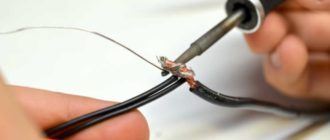
In manual arc welding with coated electrodes, the arc is excited when the electrode touches the part being welded, as a result of the closure of the electrical welding circuit.
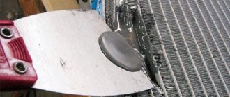
During the welding process, the coated electrode is applied to the part being welded as the electrode melts and is mixed along the joint with transverse vibrations to give the desired shape and size of the weld.
Movements of a coated electrode during welding
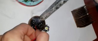
During the manual arc welding process, the coating and the electrode metal wire melt. The expanding coating forms slag and gases are released. The slag envelops drops of molten metal that appear when the electrode rod melts.
In the bath, the slag floats to its surface and forms a protective layer that protects the metal from interaction with atmospheric air. In addition, rising to the surface of the weld pool, the slag cleanses the molten metal of harmful impurities.
The welding gases formed when the coating melts displace air from the welding zone and, thereby, protect the weld pool from interaction with oxygen and nitrogen.
The liquid slag hardens and forms a hard slag crust on the surface of the weld, which is removed after welding. That is, the components included in the coating of the welding electrode protect the weld pool and the solidifying metal of the welded joint from reactions with atmospheric gases and clean the metal during the chemical reactions occurring in the weld pool.
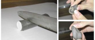
Covered electrodes are used for welding steels, cast irons and non-ferrous metals of various thicknesses. Coated electrodes are also used for surfacing to restore worn parts and obtain coatings with special properties, mainly anti-corrosion and wear-resistant.
The welder moves the welding electrode along the weld and feeds it into the welding zone as it melts.
In this regard, the stability of the process and the quality of welding depend on the qualifications of the welder and his visual-motor coordination, since the length of the arc, the inclination of the electrode, and the speed of its movement will change, which leads to a change in the mode parameters - arc voltage and welding current.
When manual arc welding with coated electrodes, to ensure stability of welding modes, welding current sources with steeply falling current-voltage characteristics are used.
Schematic diagram of manual arc welding with coated electrodes
Advantages of manual arc welding:
- manual use is possible in various, most inconvenient spatial positions;
- welding can be performed in hard-to-reach places;
- versatility of the method, the ability to weld products of various configurations;
- applicability to a wide range of different steel grades;
- high mobility.
Disadvantages of this method:
- few highly qualified welders;
- it is impossible to guarantee the quality of the welded joint;
- low welding productivity;
- unfavorable working conditions.
Reasonable applications:
- welding of metal structures, pipelines;
- It is rational to use when welding short seams.
Technology of manual arc welding with coated electrodes
Manual arc welding technology includes the following operations: cutting and preparing welding edges, exciting the welding arc, moving the electrode during welding, the order of applying welds depending on the grade of materials and the design of welded joints.
Manual arc welding requires high-quality preparation of the edges and adjacent surfaces of the parts being welded. Mechanical processing and cleaning of welded parts is performed on machines or manually.
The welded edges are cleaned to a metallic shine; there should be no traces of rust, a loose layer of scale, dirt, or oil stains, because insufficient preparation will lead to defects and, as a result, a decrease in the strength characteristics of the welded joint.
The welded edges and the adjacent metal surface with a width of at least 20 mm are subject to mandatory cleaning;
The form of edge preparation for manual arc welding with coated electrodes is established by the standards for structural elements of welded joints, depending on the thickness of the parts. The bevel angle of the edges, the bluntness and the gap between the parts to be joined must be uniform and not exceed the established tolerances.
Structural elements of welded joints
Assembly and preparatory work should be carried out in such an order that the structure is located conveniently for work and welding in the lower position. All products received for assembly must be checked for compliance with the drawings and the correct preparation of edges for welding.
To prevent deformations during the welding process, assembly should be carried out using tacks or rigidly fixed jigs. For tack welding, the same electrodes are used as for welding, unless otherwise specified in the technical documentation. The length of the tacks must be at least 50 mm in increments of at least 500 mm.
To avoid defects at the end of welding, it is necessary to use lead strips.
The welding arc is ignited in two ways: the welder touches the end of the coated electrode to the surface of the work being welded, or strikes the end of the electrode along the surface of the metal and quickly moves it to the side by about 2-4 mm. This is how the arc is excited. When welding, the arc length should be kept constant, as short as possible, for which the welder feeds the coated electrode as it melts.
An arc that is too long does not provide the required depth of penetration of the base metal, there is excessive spattering of the metal, and poor protection from atmospheric air, as a result of which unacceptable defects may form. A short welding arc provides fine droplet transfer of metal, the coated electrode melts evenly, the welding process is more stable than with a long arc.
If the welding arc breaks, the breakage area should be cleaned. Welding should be resumed by moving 5 - 10 mm away from the break point onto the previously deposited bead, and carefully weld the crater formed at the break point.
When welding, the electrode must be held at a certain angle to the parts being welded. The inclination of the electrode depends on the spatial position, thickness and grade of the base metal, the diameter of the electrode of its type and the thickness of the coating. Welding can be carried out from left to right, right to left,
from yourself and to yourself. Regardless of the direction of welding, the electrode must be inclined to the axis of the seam so that the base metal is melted to the greatest depth and the seam is formed correctly.
Source: https://svarkka.ru/%D1%80%D1%83%D1%87%D0%BD%D0%B0%D1%8F-%D0%B4%D1%83%D0%B3%D0% BE%D0%B2%D0%B0%D1%8F-%D1%81%D0%B2%D0%B0%D1%80%D0%BA%D0%B0-%D0%BF%D0%BE%D0% BA%D1%80%D1%8B%D1%82%D1%8B%D0%BC%D0%B8-%D1%8D%D0%BB%D0%B5%D0%BA/
Manual arc welding modes: parameters, electrodes
Despite the emergence of new convenient equipment, manual welding does not lose its position. I am attracted by the ease of use and the absence of the need for large expenditures. In order for the weld to be of the highest quality, it is necessary to carry out preparatory work, which includes establishing the modes necessary for a particular type of material to meet the requirements of the technological process.
The manual arc welding mode is the setting of parameters that maximally guarantee the formation of a weld that has the required dimensions and configuration, as well as the characteristics necessary for a particular connection.
The parameters of the manual arc welding mode are divided into fundamental and complementary. The selection and installation of parameters is made by the welder himself according to existing requirements.
The choice is influenced by the type of welded joint, the article number of the metal of the parts being welded and the current conductor, and the spatial arrangement.
Main settings
The most significant parameters of manual arc welding:
- current;
- voltage;
- polarity;
- electrode diameter;
- speed;
- amplitude of vibrations across the seam.
The type and size of these parameters are selected by the welder before starting work based on recommendations and personal experience.
Current value
This value significantly affects the quality of the resulting seam and the speed of the welding process. There is a direct relationship between the parameters: the amount of current during welding is set according to the diameter of the selected electrode, and the diameter, in turn, depends on the thickness of the elements being welded.
To more accurately calculate the current value, use a formula in which it is directly proportional to the diameter of the electrode. In this case, a correction factor is applied. It is different for different diameters. At what current value is manual arc welding carried out? With a weak current, the stability of the arc is disrupted, the seam will not be completely welded, which causes cracks to appear. An increased current value causes a rapid welding process and leads to increased spatter distribution.
Electrode diameter
The choice of welding mode for manual electric arc welding includes the need to correctly determine the required electrode diameters. Electrodes with a diameter greater than 6 mm are heavy, making it difficult to hold them in the desired direction for a long time. In addition, when using such electrodes, the root of the seam is poorly welded.
If a multi-pass option is used, then the first layer is carried out with a 2-3 mm electrode, and for subsequent layers a larger diameter can be used. This is of great importance when welding critical structures, since a smaller diameter provides better penetration of the root. With one pass, you can immediately use a large-diameter electrode.
When solving the problem of choosing the correct electrode diameter, the type of surfaces to be welded is considered. For example, electrodes of small diameter have proven themselves to be good for welding cast iron products. At the same time, the heat level decreases and a small cross-section bead is formed. If preliminary cutting of the edges has been carried out, then it is possible to use electrodes with a diameter of 3 mm, without focusing too much on the thickness of the parts.
Arc voltage
This parameter depends on the arc length, that is, the distance from the end of the electrode to the metal surface. The arc has different sizes. More arc means more voltage. Melting requires a significant amount of heat. The weld seam becomes wider and the penetration depth is smaller.
The voltage depends on the diameter of the electrode and the current value. It is in the range of 18-45 V. The optimal choice of manual arc welding mode regarding voltage involves welding with a short arc. In this case, the voltage will not exceed a value of 20 V. An important circumstance for obtaining a good seam is the constancy of the selected arc.
Speed
Covered electrode manual arc welding modes include speed setting. To avoid overfilling the bath and, as a result, the occurrence of smudges on the metal, you should select the optimal speed value and maintain it constant throughout the entire process. High speed will lead to insufficient weld penetration, which will cause cracks.
If the movement is too slow, the liquid metal will begin to collect in front of the arc. The seam will be uneven and lack of penetration will appear. To obtain a successful seam, the speed should be 35-40 m/hour. Then the weld pool will be on top of the surface of the edges, without forming a flow down. Its transition to the connection will be smooth, no sagging or undercuts will form.
The seam width decreases as the speed increases.
Polarity
As a rule, constant current is used for welding work. Direct polarity with constant current makes it possible to weld thick parts. To avoid burns when connecting thin metals, reverse polarity is included. AC welding is practically not used because it reduces productivity.
The choice of welding mode for manual arc welding lies, in particular, in the ability to carry out the process with different polarities. In the direct version, the current conductor is connected to the minus terminal, and the metal connection to the plus. The elements of the welded joint begin to melt more intensely than the electrode. This is an advantage when welding thick metal parts.
Reverse polarity is obtained by connecting the electrode to positive and the metal parts to negative. This provides an intense electrode melt that exceeds the melting of parts.
The explanation is quite simple and corresponds to physical laws. Where there is plus, there is more heating. Accordingly, with straight polarity, the parts being welded heat up higher. It becomes possible to connect large products. Using this type of polarity on thin parts will cause burns and the seam will be of poor quality. Therefore, to connect thin parts, reverse polarity is provided.
Features for vertical placement
Welding in a vertical position is more difficult compared to the horizontal version. Therefore, the choice of arc welding modes in this case is especially important.
How is the welding current adjusted in a vertical position? The first requirement relates to the arc - it must be short. The volume of the weld pool should not be large. To reduce it, electrodes with a small diameter should be used, and the current should be set 10-15% less than when welding is carried out in a horizontal position at the bottom.
Extra options
Electric arc welding modes include not only basic, but also parameters that complement them. Such arc welding modes also influence the final weld.
Electrode stick out
Electrode extension is the distance from the end of the electrode to the surface of the metal part. It influences the welding process and the size of the resulting seam.
Increasing this parameter reduces the stability of the arc. The metal begins to spatter more strongly. The small overhang makes it difficult to observe the welding process. Spraying occurs on the nozzle.
Electrode coating thickness
Manual arc welding modes include the characteristics of the electrodes, in particular, its coating, namely its thickness. This parameter is regulated by GOST 9466. Optimal coating requires its end size to be in the range of 0.5-2.5 mm. The use of current conductors with such a coating thickness ensures a durable seam that can withstand heavy loads.
Number of passes
The single-pass welding method involves welding in one layer. No oscillatory movements are made. It is used when welding parts of small thickness, when the seam width does not exceed 14-15 mm. At the same time, the magnitude of residual deformations decreases. For butt joints, especially when welding thick elements, several layers are used, and this method is called multi-pass.
A seam made in one pass has a larger pool. The advantages are the high productivity of the process and the cost-effectiveness of the method. Disadvantages include reduced weld ductility and too large heating zone. All seams in multi-pass welding are made with electrodes of the same size.
Interesting video
Source: https://osvarka.com/obuchenie-svarke/rezhimy-ruchnoy-dugovoy-svarki
Selecting the manual arc welding mode: basic and additional parameters
Arc welding modes (ARC) are a set of measures, indicators and parameters that must be maintained and observed for the correct implementation of a manual arc connection. Manual arc welding modes can be defined as the conditions for the normal functioning of the process of joining parts under various circumstances. Depending on different parameter indicators, the correct choice of modes for a specific type of welding joint and the choice of welding mode in general is carried out.
Conventionally, the parameters of the manual arc welding mode can be divided into two types: basic and additional. The main parameters of the welding mode for manual arc welding include the diameter of the electrode, the properties and magnitude of the welding current, and the arc voltage. Additional parameters include the position of the seam on the product, the composition and thickness of the metal, the speed of joining the product and the electrode coating. Let's consider each of them separately.
articles
- Welding current
- Electrode diameter
- Mode depending on arc voltage
- Welding speed for manual arc welding
Welding current
Current has defining properties: type, polarity and strength. By type, current is divided into direct and alternating. Polarity can be direct or reverse.
Most welding machines operate on direct current. The difference between direct current and alternating current is that direct current does not change in direction or magnitude. Thus, it ensures the stability of the arc.
The only disadvantage of direct current in the process of joining metals is the possibility of a magnetic blowing effect. It occurs when connecting large structures, when an extraneous magnetic field (from magnetized products) affects the magnetic field of the arc.
In this case, the arc begins to “run out” beyond the area where the seam is located and combustion stability decreases sharply. This disadvantage can be combated by
- fencing the work area with special screens that protect from “extra” magnetic fields
- grounding of welded surfaces
- identify possible options for using alternating current
The advantage of working on direct current is a stable arc and the ability to select polarity. Direct polarity is also called electrode-negative, reverse polarity is also called electrode-positive. Reverse polarity occurs when the electrode is connected to the positive and the metal to the negative. With direct polarity, the opposite is true. The difference between the polarities is as follows.
The laws of physics say that where the plus is connected, that element heats up more. Thus, with straight polarity, the metal product heats up more. This polarity should be used to join thick parts, since this process requires more melting of the metal to obtain a good weld.
If direct polarity is used on a thin product, it will “burn” and the seam will turn out to be of poor quality. For thin metals, reverse polarity is carried out.
The amount of current is determined by the characteristics of a particular welding machine. In modern models, these indicators are indicated in the instructions. If for some reason you do not have instructions, then the current strength can be selected depending on the diameter of the electrode used.
It is not allowed to use a current strength that is more suitable for a particular electrode. In this case, the electrode coating used to make the connection will be damaged and the arc will operate unstably.
Using an electrode that is too large also has a bad effect on the process of joining metals: the current density decreases, the arc “runs away,” its length changes, and the weld does not turn out smooth and of high quality.
Mode depending on arc voltage
Arc voltage is related to its length. Typically the voltage is set in the range of 20-36 V. It increases as the arc length increases. The length of the arc can be short, medium and long.
Arc length is the distance from the tip of the electrode to the metal being welded. To make a quality connection, you need to ensure a stable arc size. It is believed that for beginners it is easier to maintain an average arc size. It is possible to make a high-quality seam with a short arc, but this requires experience and professionalism.
Welding speed for manual arc welding
Manual electric arc welding is characterized by the speed of its implementation. It affects the width of the seam. The faster the speed, the narrower the seam. When working slowly, the seam is wide. Transverse movements of the electrode during the joining process also affect the width and also the depth of the seam.
Do not cook too quickly or too slowly. When working very quickly, spaces unfilled with metal will form, which can cause cracks. Working the electrode very slowly allows the molten metal to spread, which will make the product of poor quality.
The movements of the electrode end can also be different (zigzags, herringbones).
Options for electrode direction when welding
Thus, choosing a manual arc welding mode is a set of actions aimed at finding the necessary parameters for connecting a particular product. If you are not a professional or even a complete beginner in this matter, then choosing the welding mode required for a particular product may not work the first time.
But this is why there is practice, reference information, and instructions for reference, which indicate the parameters of manual arc welding depending on various indicators. It is worth noting that in each case all parameters are selected individually.
You can select manual arc welding modes with coated electrodes yourself.
Source: http://home.nov.ru/vybor-rezhima-ruchnoj-dugovoj-svarki-osnovnye-i-dopolnitelnye-parametry/
Basic principles of manual arc welding
One type of permanent connection of materials carried out manually is manual arc welding. It is based on the action of an electric arc that occurs during a controlled short circuit.
The welder manually controls the electrode and, if necessary, supplies filler material. Although the productivity of the manual method is not high, it is often used at home. The equipment for it is quite accessible, and anyone can learn manual welding if they wish.
Technology Brief
When manual electric arc welding is used, the metal is quickly heated to its melting temperature by the action of an electric arc, which occurs as the effect of air breakdown between the electrode and the mass (parts being welded). Additional material is introduced into the weld, which allows you to fill the gap between the parts being welded.
At the heating point, a so-called weld pool is formed, which is a zone of mixing of the molten metal of the part with the additive material.
Light molten slag floats up - this is the burnt coating of a consumable electrode or the remains of a non-consumable rod. The slag protects the hot metal from the harmful effects of gases in the atmosphere.
This influence can lead to oxidation of the seam and the penetration of gas atoms into its structure, as a result of which the seam will not acquire the required strength.
Manual arc welding is performed with a consumable or non-consumable electrode. The first is itself a filler material, the second requires the introduction of filler wire into the melt.
There are various hand welding technologies. The least complex and costly of them requires only an AC or DC welding machine and the necessary equipment for the welder, but this method is suitable, as a rule, only for ferrous metals that normally tolerate contact with oxygen. To protect the weld pool, where steel and iron are melted, only the environment generated by the protective coating of the electrode is sufficient.
More complex methods, such as argon arc welding, require a special torch with a nozzle through which argon or other shielding gas is supplied.
The welding arc is initiated by a short circuit when the electrode contacts the ground. The arc temperature can reach 5000 °C.
Purpose
The use of manual arc welding is very wide - from everyday work around the house and country house to industry, including high-tech. Among the main industries and national economy where it is used are:
- various service and repair work, for example, automotive equipment;
- welding of pipes for water, gas, oil products.;
- shipbuilding (welding of hull plates);
- many types of mechanical engineering.
The principle of manual welding is often used for surfacing another metal onto the surface of a part. In everyday life, gazebos, benches, barbecues, swings are welded using the manual arc method, and metal products are repaired.
Technical capabilities
Manual welding has significant limitations on the thickness of the parts being welded; this is its main disadvantage. As a rule, sheets thicker than 10 mm are not welded using this method.
Others include the relatively low speed of the process and the direct dependence of the result on the skill of the welder. The manual welding process, like any manual process, is difficult to standardize: the result depends on many factors. Among them:
- type of current source;
- the power of the source;
- characteristics and properties of the processed alloy;
- edge thickness;
- compliance of the electrodes with the task assigned to them;
- well-chosen welding mode.
The peculiarities of arc welding are that a relatively low voltage and a very high current are used to produce it. The arc voltage ranges from 30 to 90 V (many welding machines for home use are rated at an average value of 48 V), but the current is very high - from 90 to 350 A.
Selection of welding parameters
The main parameters of arc welding are current and voltage (but it is fixed). Frequency is less important, since nowadays, as a rule, installations for DC welding are used - inverters.
For welding using electricity, regardless of the method, a direct proportional relationship applies: the thicker the metal, the greater the current should be at a fixed voltage. For comparison: sheets 3 mm thick are cooked with a current of 175-185 A, 5 mm - at least 200 A, 10 mm - 300-330 A.
It is strongly recommended that, in order to avoid burning and severe spattering of the metal, weld with the minimum current possible.
But at the same time, the thickness of the welding electrode and its correspondence in chemical composition to the metal that is supposed to be processed is also very important.
A standard arc welding electrode has a thickness of 3 mm. It is suitable for welding parts with an edge thickness of 2-3 mm. For thicker metal, you can follow the rule that the diameter of the electrode should be 1-2 millimeters less than the thickness of the metal plates that are supposed to be connected with it.
The maximum thickness of electrodes produced by industry is 6 mm. They are suitable for welding ten-millimeter steel sheets.
Each pack of electrodes has its own marking, indicating for what purpose they are intended.
What does marking mean?
It is impossible to imagine manual arc welding without electrodes. Their marking determines what metals they are intended for, what thickness and composition of the coating they have, in what position they should be held when welding (vertically, horizontally, at an angle), what metals they are intended for. The nature of the marking is alphanumeric.
The first letter after the name and brand of the electrode is the letter that determines its purpose. U - for low-alloy and medium-carbon steels, T - for heat-resistant alloy steels. The letter N is for surfacing, A is for ductile metals.
Next comes a letter indicating the thickness of the coating. M - thin coating, C - medium, D - thick, G - extra thick.
The thickness of the coating is determined as a percentage relative to the rod itself.
The next letter of the code indicates the type of electrode. If it is the letter E, then the electrode is consumable.
This is followed by numbers that characterize tensile strength, relative elongation and impact strength retention temperature. They are important only for professional welders working in particularly critical production.
They are followed by one or two letters indicating the coating material of the electrode. A means acidic compound, B - alkaline, C - cellulose, R - rutile, P - other types. Mixed types of coating are possible, such as RC.
The last two digits of the code indicate one of the most important parameters - the position in space in which manual arc welding can be performed, and the current characteristics for welding.
For example, code “13” should be read as 1 and 3. 1 - you can cook in any spatial position, 3 - you must use a current of reverse polarity or an alternating voltage of 50 V.
Types of equipment
Equipment for manual arc welding, as a rule, is a welding machine of a transformer or inverter type, equipped with a cord for connecting to a power source and two contact cords with holders for the electrode and for ground.
The difference between the devices is that the transformer welds only with alternating current, and the inverter or semi-automatic device has a current rectification function for better arc welding quality and the ability to work in direct or reverse polarity.
With direct polarity, the conductive rod is connected to the minus, and the part to the plus. The opposite is the opposite. Different types of metals and alloys require either forward or reverse welding.
GOST requirements
Manual arc welding is subject to the requirements of GOST 5264 80 and GOST 11534 75. These are the main standards that must be followed when welding.
The first - GOST 5264 80 - regulates the technology for creating welded joints of various configurations from steels, pure nickel and nickel-iron alloys.
It consists of a large number of tables that provide drawings of the types of connections that must be met. GOST also indicates the limits of permissible errors and other important numerical parameters.
GOST 11534 75 describes the main types, sizes and design features of products made of low-alloy and carbon steels that can be bonded by manual arc welding with a consumable electrode.
It does not apply to the non-consumable electrode welding methodology. The document also consists of tables containing examples of connections, permissible error limits, thicknesses and angles of connected parts.
Source: https://svaring.com/welding/vidy/ruchnaja-dugovaja-svarka
Selecting the mode for manual arc welding
Arc welding modes are a set of controlled characteristics that determine the conditions for welding operations. Correctly selected mode parameters for manual arc welding, maintained throughout the entire welding period, guarantee a high-quality connection of individual metal samples. These characteristics are conventionally divided into the following indicators.
Basic modes
- Current parameters: type, size, polarity
- Arc voltage
- Number of passes
- Electrode diameter
- Performance
Additional
- Electrode parameters: elements included in its composition, wire coating thickness, wire extension size
- Cleaning quality, edge configuration of welded workpieces
- The position of the electrode wire, the samples being connected during the welding process
Arc welding diagram
The filling pattern of the joint seam determines the ability of the resulting joint of individual parts to absorb the expected loads, affects the deformation of the suture mass, and the parameters of internal stress.
Seam joints may vary in length:
- short - up to 30 cm;
- medium - 30-100 cm;
- long - from 100 cm.
Depending on the length of the weld, the technique for filling it varies.
If one welding pass is not enough to fill the seam joint in full, then additional seams are applied.
- Multilayer seam - if the number of layers corresponds to the number of passes with electrodes.
- Multilayer-pass seam - if several passes are required to apply some layers.
Selection of current, electrode cross-section diameter
Current strength when using manual electric arc welding is one of the most important indicators affecting working productivity and the quality of the seam joint.
Most often, the delivery of welding equipment includes an instruction manual, which indicates the recommended parameters.
If instructions are not provided, then it is recommended to select the current strength taking into account the diameter of the electrodes used, many manufacturers of which place the relevant information on the packaging.
Example of the relationship between current, electrode diameter, material thickness
I t, A10-2030-4545-100100-160120-200150-200160-250200-350| D el., mm | 1 | 1,5-2 | 3 | 3-4 | 4 | 4-5 | 5 | 6-8 |
| T m, mm | 0,5 | 1-2 | 3 | 4-5 | 6-8 | 9-12 | 13-15 | 16 |
Type, current polarity
These parameters depend on the type and thickness of the metal of the parts being welded. With constant electric current with reverse polarity, the electrode releases more thermal energy.
DC current:
- for connecting alloy steel samples to prevent overheating;
- for welding thin metal products to prevent them from burning.
AC current:
- for workpieces made of carbon steels, for the purpose of economy.
Manual arc welding modes - what you need to know?
Gas shielded arc welding is an electric welding that uses a welding arc, it melts the metal due to its high temperature, and the shielding gas that is supplied to the arc area destroys oxidized metal spatter and prevents the metal and air from reacting. The result is a strong and durable seam connecting two metal parts.
Manual welding modes: main and secondary parameters
The manual arc welding mode is a set of all indicators that require careful compliance to maintain the arc. A well-functioning process without the influence of external factors determines the correct choice of welding mode. The main welding parameters include:
- electrode size;
- properties and current strength;
- welding arc voltage.
Secondary indicators include:
- seam location;
- metal alloy and size;
- seam adhesion speed;
- coating on the electrode.
All about the properties of current
There are three indicators of current: type, polarity and strength. It can be constant or variable. Direct current does not change its characteristics either in direction or in magnitude. It is convenient to work with, as it promotes stable and constant arc burning.
The only disadvantage of direct current when welding metal surfaces is that the effect of magnetic swelling appears. When working with large products, a magnetic field arises, which affects the magnetic field of the welding arc. The arc bends and the stability of work ends.
There are several ways to solve this problem:
- special enclosing barriers that do not allow the magnetic field of foreign objects to pass through;
- grounding of work products;
- use alternating current.
As we already know, the main advantage of direct current is stable arc burning. You can also choose the polarity. The type of current polarity can be direct or reverse. Direct polarity is created when the electrode is in contact with the minus, and the metal is in contact with the plus; it has another name - electrode-negative. With reverse polarity, the electrode is connected to the positive, and the metal to the negative, this polarity is called electrode-positive.
The quality of the seam depends on the polarity. If the element is in contact with the positive, then the heating temperature is higher. Consequently, the metal surface heats up more from the electrode-negative polarity, and thus must be used when working with thick metals. If you choose reverse polarity, then take thin sheets of products.
Direct polarity in welding thin parts will be inappropriate, since the metal will simply burn out and the weld will turn out to be of poor quality.
Each individual welding machine has its own current strength . Usually it is indicated in the instructions, but if for some reason it is not possible to familiarize yourself with the operating rules of the product, then you can focus on the diameter of your electrode.
Do not use more current than the electrode coating can withstand. This will damage the electrode and the arc will not be constant. If you take an electrode that is too large, then this option will also not be the best solution.
The current concentration decreases, the arc jumps and bends, and the weld is not of the proper quality.
Electrode size
The welding process modes are directly determined by the diameter of the electrode used. There are vertical, horizontal and ceiling seams. Depending on the thickness of the product being welded and the location of the seam, the optimal tip size is selected. But in any case, you need to start with a diameter of 4 mm. If this is a multi-layer seam, then the second and third seam can be adjusted with other electrode sizes.
(table of the relationship between electrode, metal thickness and current)
Arc length and voltage
Arc length is the distance from the end of the electrode to the point of the metal that is being welded. It directly depends on the voltage. The voltage is fixed in the range of 20-36V. And it intensifies as the arc increases. The arc is classified as short, medium and long. The smaller the arc size, the more professionalism the master should have. Beginners are advised to start by creating a medium-sized arc and carefully ensure that the size remains the same.
Welding speed
The speed at which the seam is completed depends on its appearance and quality. Too high a speed will lead to the formation of voids, and subsequently to the appearance of cracks. The seam turns out to be narrow and does not cover the required joint area. With slow movements, the seam is too wide, the molten mass spreads, and the finished product cannot withstand the load placed on it.
Side-to-side movements have a definite effect on the depth and width of the surfaces being fastened. The golden mean is good in everything. Working slowly, but not slowly, is considered the ideal method for obtaining a strong and high-quality grip. There are a sufficient number of suture options. This includes the zigzag method, Christmas trees, monograms and other shapes.
The technique for guiding the electrode when creating a seam is given below.
It takes a long time for a beginner to become a professional. The first products will certainly be clumsy and with a lot of flaws. It may not even work out at all the first time.
But for such purposes there are a number of reference books and useful tips, video information and practical aids that are used by inexperienced welders. The choice of mode is purely individual for each type of product, and choosing the right option is available to every person who has the desire.
Try experimenting with different electrode head sizes and then you will choose the best option for yourself. Also, be sure to read the article on gas welding and metal cutting.
Source: https://svarka-weld.ru/vybor-rezhima-ruchnoj-dugovoj-svarki
Welding modes - selection and parameters
When the conversation turns to such a concept as welding modes, it is necessary to realize that this is a fairly large set of various parameters, which in turn determine the conditions of the welding process. And in order for the quality of the final result to be only positive, you need to choose these same parameters correctly. And although experts conditionally divide them into primary and secondary, all of them, without exception, affect the quality of the weld.
The main parameters of the welding mode include:
- The amount of current installed on the welding machine.
- Its gender (fixed or variable) and polarity (direct or reverse).
- Welding arc voltage.
- Diameter of the electrode used.
- Speed of the welding process.
- Number of passes to fill the weld.
The secondary ones include:
- The quality of cleaning of welded workpieces.
- The shape of the joined edges.
- Type of electrode: its brand, type of coating, coating thickness.
- The angle of inclination of the electrode relative to the welding surface.
- Its position (top, bottom or side).
- How the joint is located (horizontally, vertically, at an angle).
Welding mode parameters
It should be noted that most often welders pay attention to the main parameters and their mutual relationship, but at the same time they do not lose sight of the secondary ones.
For example, the diameter of the electrodes is selected depending on the thickness of the metal parts being welded, the position of the joint, as well as the shape of the prepared edges.
And although there are tables that determine the diameter of the consumable relative to the thickness of the workpieces, it is very important to take into account the position of the electrode itself during the welding process.
Electrodes with a diameter larger than 4 mm cannot be used for ceiling welding. The same applies to the multi-pass process, because it is in this case that the root weld may not penetrate properly.
Welding current
As for the current strength, here too there are several provisions regarding the choice of welding parameters. The thing is that the more intense the current, the higher the temperature inside the weld pool. And this affects the rate of metal melting and the productivity of the welding process itself. And this is correct, but with some reservations.
- With increased current and a small diameter of the electrode, overheating occurs in the welding zone of the workpieces. This is already a decrease in the quality of the seam. Plus intense splashing of metal inside the bathtub. Often this mode leads to burnout.
- If the current strength is reduced, then this is a guarantee of lack of penetration, because at low current the arc becomes unstable. And with such an arc, the welding process often breaks down. This is the reduction in connection quality.
- If an electrode with a large diameter is selected without taking into account the thickness of the workpieces, the current density deteriorates. The reason is low cooling of the metal in the welding zone.
Not the last word in such a concept as the choice of welding mode is the polarity of direct current. With reverse polarity of the current, the penetration depth is 40% greater than with direct polarity. When using alternating current for welding, it must be taken into account that the penetration depth when using it is 15% less than when using constant current. And this is at the same current value.
Welders themselves with extensive experience set the welding current experimentally. They simply pay attention to the stable state of the arc, to its stable combustion. Beginners can use various tables or formulas. For example, one of the formulas that determines the current strength depending on the diameter of the consumable. It can be used if welding uses an electrode with a diameter of less than 3 mm.
I=30d
Welding process speed
The choice of arc welding mode also depends on the speed of movement of the electrode. This parameter is directly related to the thickness of the parts and the thickness of the seam. Its ideal value can only be considered when the area where the molten metal joins the edges of the parts is free of undercuts, burns and lack of penetration. The seam itself is a transition of a uniform shape without sagging or undercuts.
The higher the speed, less metal will get into the bath, the edges will not heat up to the required temperature, hence the lack of fusion of the seam, which will quickly crack. If the speed is lower, nodules are formed that interfere with penetration. The optimal mode is when the width of the seam is twice the diameter of the consumable.
Arc length
Another parameter that affects arc welding modes. Arc length is the distance from the end of the electrode to the top surface of the edge being welded. The ideal option is if this distance is the same along the entire length of the weld. But that's not all. It is important to choose this distance correctly.
Experts believe that the length of the arc should be equal to the diameter of the consumable used. Unfortunately, only experienced welders can withstand such a distance. Therefore, there are certain deviations. For example, for an electrode with a diameter of 3 mm, it is better to keep the distance to the edge within 3.5 mm.
Electrode angle
The position of the electrode relative to the welding plane affects the width of the weld and its penetration depth. It is considered optimal if the rod should be located perpendicular to the connection of the workpieces. But this is practically impossible, because the welding tool of the welding machine moves along the joint. Therefore, the electrode is positioned either tilted forward or tilted backward.
In the first case, the seam becomes wide, and the penetration depth decreases. This happens because the molten metal is forced out to the front of the weld pool. In the second case, on the contrary, the molten metal is pushed to the rear of the bath. Therefore, the depth of the joint is well welded in this way, but the width of the seam is noticeably reduced.
By the way, the angle of inclination of the workpieces being welded has exactly the same effect on the quality of the seam.
If welding is performed on parts that are located at a certain angle, and the electrode itself moves from top to bottom, then a thickened layer of molten metal forms under the consumable. And this is an increase in the width of the seam and a decrease in the depth of penetration.
If the movement is made from bottom to top, then there is much less molten metal under the arc, which makes it possible to deepen the welding, but at the same time obtain a small seam width.
Experts recommend installing the workpieces at a slight angle, no more than 10°. In this way, metal spreading along the seam can be avoided, which will ensure the quality of welding. In this way, lack of penetration and undercuts can be avoided.
As you can see, manual arc welding modes are a set of measures based on the correct selection of certain parameters. Even the slightest deviation can lead to a decrease in the quality of the connection between two metal workpieces.
Source: https://svarkalegko.com/tehonology/rezhimy-svarki.html
Read online Welding: A practical guide for electric and gas welders page 23. Large and free library
Rice. 60. Spring clamp:
1 – clamp head;
2 – guide bushing;
3 – spring
Rice. 61. Clamp (a) and installation clamp (b): 1 – handle; 2 – screw; 3 – nut; 4 – heel; 5 – body; 6 – emphasis; 7 – lanyard; 8 – parts fixed in a given position
Rice. 62. Manipulator: a – position of the faceplate (upper part) of the manipulator for welding the unit in a horizontal position; b – position of the manipulator faceplate for boat welding
For welding large-sized sheet structures, various jigs, stands, tilters, installations, etc. are used. These devices ensure the fixation of parts in a position convenient for welding. Some types of tilters and installations are shown in Fig. 63.
Control of products assembled for welding is carried out mainly by mating and overall dimensions. Dimensions are checked using metal tape measures, rulers or templates.
Rice. 63. Two-post rotary tilter: 1 – front drive post; 2 – rotating frame; 3 – rear non-drive strut; h – variable height for installing the structure to be welded in a given position
Inspection of products after welding is carried out according to the technical specifications for the product being welded, which specifies the requirements for the quality of welds and their sizes.
3. Selection of modes for manual arc welding
The quality of welds in manual arc welding depends on the qualifications of the welder. The welder must be able to quickly ignite the arc, maintain its required length, evenly move the arc along the edges of the work being welded, perform the necessary oscillatory movements of the electrode during welding, etc.
The most widely used method is manual arc welding (MAW) using coated metal consumable electrodes using direct and alternating current.
With correctly selected RDS modes in the lower position, it is possible to ensure high-quality penetration of the weld metal up to 3-4 mm. To avoid lack of penetration of the weld metal when welding metal of large thicknesses and to achieve good formation of the weld, various forms of cutting the edges of parts are used.
Forms of edge preparation depending on the thickness of the parts being welded and various welding methods are given in Table. 32.
Table 32
Forms of edge preparation depending on the thickness of the parts to be welded
Note. P – manual welding; A – automatic welding; D – welding in CO2 environment.
When choosing the form of preparation of the edges of parts of welded joints, along with the need to ensure penetration, the technological and economic conditions of the welding process are taken into account. Thus, butt joints with V-shaped beveled edges are recommended for use on metal with a thickness of 3-26 mm.
With a large thickness, the mass of deposited metal increases sharply. For metal thickness up to 60 mm, an X-shaped bevel of the edges is used. In the latter case, the amount of deposited metal compared to the deposited metal with a V-shaped bevel of the edges is reduced by almost 2 times.
This also leads to a decrease in stress in the weld and a decrease in deformation of the welded joint.
The welding mode is the set of characteristics of the welding process that ensures the production of welds of specified sizes, shapes and quality. With RDS, such characteristics are: electrode diameter, welding current strength, arc voltage, welding speed, type of current, polarity, etc. The approximate relationship between the electrode diameter and the thickness of the sheets of the product being welded is given below:
When welding multi-pass seams, they tend to weld all passes using the same conditions. The exception is the first pass. When manually welding multi-pass seams, the first pass is performed, as a rule, with electrodes with a diameter of 3-4 mm, since the use of electrodes of a larger diameter makes it difficult to penetrate the root of the seam.
For approximate calculations of the welding current strength, in practice the following formula is used:
Ist = kd,
where d is the diameter of the electrode rod, mm;
k – coefficient taken depending on the diameter of the electrode:
When the welding current is insufficient, the arc burns unstably, and when the current is excessive, the electrode melts too intensely, as a result of which spatter losses increase and seam formation deteriorates. The permissible current density depends on the diameter of the electrode and the type of coating. The larger the diameter of the electrode, the lower the permissible current density, as cooling conditions worsen.
The type of coating affects the melting rate of the electrode. The values of the permissible current density in the electrode depending on the diameter of the rod and the type of coating are given in Table. 33.
Table 33
Permissible current density (A/mm2) in the electrode during manual arc welding
The arc voltage during RDS varies within 20-36 V and is not regulated when designing manual welding processes.
The welding speed is selected taking into account the need to obtain a layer of deposited metal with a certain cross-sectional area. The welding speed is selected experimentally when welding test samples.
The type and polarity of the welding current depend mainly on the thickness of the metal and the brand of the electrode. Low-carbon and low-alloy steels of medium and large thickness are often welded using alternating current.
Approximate welding modes for structural steels are given in Table. 34.
Table 34
Approximate welding modes for structural steels
Control questions:
1. What are the different forms of edge cutting used for?
3. What is meant by welding mode?
4. What is the influence of various characteristics on welding conditions?
4. Methods for making seams along the length and cross-section
For a novice welder, it is very important to master the skill of striking an arc. The arc is ignited by briefly touching the end of the electrode to the workpiece or by striking the end of the electrode on the metal surface (Fig. 64).
The arc is “guided” in such a way that the edges of the parts being welded are fused to form the required amount of deposited metal and the specified weld shape. The main, most widely used methods of moving the end of the electrode during RDS are shown in Fig. 65.
There are various ways to make seams in length and section. The choice of method for making seams is determined by the length of the seam and the thickness of the metal being welded. Conventionally, seams with a length of up to 250 mm are considered short, seams with a length of 250-1,000 mm are considered medium, and more than 1,000 mm are long (Fig. 66).
Rice. 64. Methods of igniting an arc with a consumable coated electrode: a – touching the electrode at a point; b – striking the end of the electrode on the metal surface
Rice. 65. The main methods of moving the end of the electrode during RDS: a, b, c, d - with ordinary seams; d, f, g – for seams with increased heating of the edges
Source: https://dom-knig.com/read_239085-23
Arc welding mode | Metal welding
Arc welding mode is understood as a group of indicators that determine the nature of the welding process. These indicators affect the amount of heat introduced into the product during welding.
The main indicators of the welding mode include: the diameter of the electrode or welding wire, welding current, arc voltage and welding speed.
Additional indicators of the welding mode: type and polarity of current, type and brand of coated electrode, angle of inclination of the electrode, metal preheating temperature.
Mode selection
Selecting a manual arc welding mode often comes down to determining the electrode diameter and welding current. The welding speed and arc voltage are set by the welder himself, depending on the type (type) of the welded joint, the grade of steel and electrode, the position of the seam in space, etc.
Multi-layer seams
In multilayer butt and fillet welds, the first layer or pass is made with an electrode with a diameter of 2 - 4 mm; subsequent layers and passes are made with an electrode of larger diameter, depending on the thickness of the metal and the shape of the bevel of the edges.
In multilayer seams, welding the first layer with a small-diameter electrode is recommended for better penetration of the root of the seam. This applies to both butt and fillet welds.
Vertical welding
Welding in a vertical position is usually performed with electrodes with a diameter of no more than 4 mm, less often 5 mm; electrodes with a diameter of 6 mm can only be used by highly qualified welders.
Ceiling seams, as a rule, are made with electrodes no more than 4 mm.
4.Manual arc welding. Mode parameters. Application area
Mode parameters.
Manual arc welding modes constitute a set of controlled parameters that determine the conditions of the subsequent welding process.
The parameters are divided, conditionally, into basic and additional.
The main parameters of the mode are:
- electrode diameter;
- the magnitude of the current, as well as its type and polarity;
- electric arc voltage;
- number of passes;
- welding speed.
Additional parameters of the manual arc welding mode:
- the amount of electrode extension, the thickness of its coating, as well as its position and composition;
- product position;
- shape of prepared edges;
- quality of cleaning of prepared edges.
Calculation of manual arc welding modes is carried out by calculating the ratio of the electrode diameter to the thickness of the parts being welded.
Application area.
Manual arc welding is used in domestic conditions, in construction, and also for welding pipelines.
5. Automatic submerged arc welding. Welding mode parameters and their influence on metal penetration parameters
Automatic and semi-automatic submerged arc welding is one of the main methods of performing welding work in industry and construction.
Possessing a number of important advantages, it has significantly changed the technology of manufacturing welded products, such as steel structures, large-diameter pipes, boilers, and ship hulls.
As a result of changes in manufacturing technology, changes have also occurred in the welded structures themselves: welded-cast and welded-forged products are widely used, providing enormous savings in metal and labor.
6. Mechanized welding in shielding gases. Types of methods and their features
Mechanized (or semi-automatic) welding is arc welding in which the supply of a consumable electrode and the movement of the arc relative to the product are performed using mechanisms. It can be used to make any welded joints: butts, corners, T-joints, lap joints, etc.
Protective gases.
Argon is a monatomic gas, colorless and odorless, heavier than air.
Pure argon is used when welding critical seams and when welding high-alloy steels, titanium, aluminum, magnesium and their alloys.
Helium is a monatomic inert gas without color or odor.
The essence of the method
Welding in shielding gases can be performed with a non-consumable, usually tungsten, or consumable electrode. In the first case, the weld is obtained by melting the edges of the product and, if necessary, filler wire fed into the arc zone. The consumable electrode melts during the welding process and participates in the formation of weld metal.
Three groups of gases are used for protection: inert (argon, helium); active (carbon dioxide, nitrogen, hydrogen, etc.); mixtures of inert, active or first and second group gases.
The choice of protective gas is determined by the chemical composition of the metal being welded and the requirements for the properties of the welded joint; process efficiency and other factors.
Source: https://studfile.net/preview/6152775/page:2/
Manual arc welding mode parameters: current, electrode diameter, welding speed, etc.
The set of factors that influence the quality of the resulting seam and ensure stable progress of the welding process are called welding mode parameters.
When performing manual arc welding, the following welding mode parameters are distinguished:
- electrode diameter;
- welding current strength;
- type and brand of electrode;
- arc voltage;
- type of current and polarity;
- welding speed;
- location of the seam in space;
- heating and heat treatment;
- ambient temperature.
The last three parameters are considered additional, the rest are basic for this type of welding.
Current strength
The current strength is set after selecting the electrode depending on its diameter. To calculate the welding current when welding in the lower position, there is a formula:
Ist = delK
where Ist is the current strength, A; K - proportionality coefficient (changes its value depending on the type and diameter of the electrode).
Table 2. The value of the proportionality coefficient depending on the diameter of the electrode| Electrode diameter, mm | 1-2 | 3-4 | 5-6 |
| Proportionality coefficient (K), A/mm | 25-30 | 30-45 | 45-60 |
You can use a simplified formula for selecting welding current for manual arc welding:
Ist = (20 + 6 div)div
In order to avoid waste when welding in the lower position of metal with a thickness of less than 1.5 divisions, the welding current is reduced by 10-15% of the calculated one. If the metal thickness is more than 3 div, the current is set to 10-15% more.
When welding seams in a vertical position, the current is reduced by 10-15%, and in the ceiling by 15-20% of that selected for welding in the lower position.
If welding work is performed with high-quality, certified electrodes, the current strength should be set in accordance with that recommended on the packaging with the electrodes. The calculations above can be used in the absence of recommendations from the manufacturer as an alternative method.
Once the amperage is selected, the welder must place several beads on a separate plate of metal. In this case, the width of the seam and the depth of penetration are assessed. If necessary, the current strength is additionally adjusted.
Too small current modes lead to unstable combustion of the welding arc. Lack of penetration appears in the welded joint, and labor productivity decreases.
Increased current values are accompanied by its overheating, high combustion rate, lack of fusion, intense metal spattering and deterioration in the appearance of the seam.
A balanced current strength is characterized by a moderate melting rate of the electrode, stable arc burning with insignificant metal spattering.
Electrode type and brand
First of all, it is necessary to select electrodes that ensure uniformity of the chemical composition of the base metal and the metal rod of the electrode. Also, the type and brand are selected depending on the spatial position of the seam, the required density of the seam, ambient temperature, strength of the product and operating conditions of the structure. Using an electrode, you can give the seam the necessary properties.
Arc voltage
The welder can adjust the arc voltage by changing the length of the welding arc. Depending on the arc length in manual arc welding, the voltage is in the range of 16-40 V.
According to welding technology, the voltage should be kept at 16-20 V. For this, welding is usually performed with a short arc measuring 0.5 -1 thickness of the electrode diameter. This value may vary depending on the brand of electrode and the position of the seam in space.
Type and polarity of current
AC welding is used to join low-carbon and low-alloy steels (type 09GS) in construction and installation conditions with rutile-coated electrodes. For welding thick structures made of low-carbon steels. If magnetic blast occurs during welding with direct current sources.
DC welding can be divided into two processes - manual arc welding with direct and reverse polarity.
On straight polarity
Direct polarity is used for welding cast iron and deep penetration of the base metal. For welding low-, medium-carbon and low-alloy steels with a thickness of 5 mm or more using electrodes with calcium fluoride coating: UONI-13/45, UONI-13/55, etc.
On reverse polarity
Reverse polarity is used for welding sheet metal of low thickness and welding with an increased melting rate of the electrode. For welding low-carbon steels (type 16G2AF), low-, medium- and high-alloy steels and alloys.
To indicate a certain type of current, the designations AC and DC are often used today.
The abbreviations AC and DC (short for alternative current and direct current) mean alternating and direct current, respectively.
The welding speed is selected by the welder depending on the properties of the base metal, the characteristics of the electrode, the position of the seam, etc.
The welding speed should be such that the liquid metal of the weld pool rises slightly above the surface of the base metal with a smooth transition to it without undercuts or sagging.
To prevent overheating of the metal, high-alloy steels are welded at a higher speed.
Seam location in space
The location of the seam in space affects the choice of the main parameters of the manual arc welding mode. Manual welding is used for joints in all spatial positions, but the bottom position is considered the most convenient. It is worth considering the position of the seam in space when calculating the main parameters and choosing an electrode.
Preheating and post-heat treatment
Preheating of the base metal and subsequent processing are used for welding steels prone to the formation of hardening structures - medium and high carbon steels. For welding cast iron, non-ferrous metals and their alloys. The temperature and method of heating and processing depends on the thickness of the base metal, chemical composition and size of the structure.
Ambient temperature
All steels can be divided into four groups according to the degree of their weldability. Steels of groups II, III and IV cannot be welded at temperatures below -5 °C.
Source: http://osvarke.net/mma/rezhimy-ruchnoj-dugovoj-svarki/