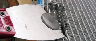
Spot welding modes, parameters
Spot welding in production
The spot welding mode is set by the following basic parameters: current strength or density, heating time, pressure, diameter of the working part of the electrode. In addition, the pre-compression time of the electrodes tсж, the forging time tnp, the shape of the working part of the electrode and the material for its manufacture are often specified . Modes of special types of spot welding have some additional parameters.
Soft modes are characterized by low current strength and long heating time; for hard modes, the current strength is high and heating time - the mode option must be made taking into account the specific production conditions and requirements for the welding joint.
Spot welding
Welding in soft modes is accompanied by the formation of a wide heating zone, which facilitates the deformation of the metal and allows us to limit ourselves to not very high requirements for the accuracy of straightening workpieces, as in hard modes.
Exact. welding
Hard modes provide higher performance and less power consumption. Due to the fact that the surface of the parts under the electrodes heats up relatively less under harsh conditions, the electrodes heat up less and, despite the increase in pressure, their consumption decreases.
The depth2 of indentation at the welding site and warping of the product are noticeably reduced.
In general, hard modes are advisable, first of all, in mass production, where the gain in productivity and energy consumption will fully compensate for the additional costs associated with the acquisition, operation and power supply of more powerful equipment.
Current strength and density
As the thickness of the sheets being welded increases, the current strength should increase. For welding low-carbon steels of medium thickness on serial machines, the approximate selection of current strength l can be carried out according to the following relationship:
l=6500qa,
Where q is the thickness of the sheets being welded in mm.
When welding sheets of different thicknesses, the choice of parameters is made under the condition that there is sufficient heating and deformation of the thinner sheet. Therefore, in the given relationship and in subsequent ones, the value of q is related to a thinner sheet.
Current density I for hard modes is selected within the range of 120 - 360 d/Lm*, for soft modes 80 - 160 A mm2.
With increasing sheet thickness, the density is then/? decreases. When the metal of the parts being welded has increased thermal and electrical conductivity, the current density should increase. Thus, when welding aluminum or its alloys, the current density sometimes reaches 1000 A/mm2 and higher. As mentioned earlier, the current density should be selected higher when, for some reason, the pressure is assumed to be increased.
Resistance spot welding
Heating time
Like current, heating time (tcs) increases with increasing part thickness. Approximately for welding low-carbon steel at hard conditions, the heating time can be selected according to the ratio
tce — (0.1 -f-0.2) q sec.,
where q is the thickness of the thinner sheet in mm.
It is not recommended to take a shorter heating time, since random, even minor errors in the operation of the time regulator can cause serious deviations from the required heating and welding quality.
For welding sheets up to 3 mm thick in soft modes, the heating time can be selected according to the ratio.
I = (0.8×1) q sec.
Heating for too long can cause overheating of the metal in the welding zone.
For welding metals with high thermal conductivity, the welding time is assumed to be short (at high current strength); when welding hardening steels, on the contrary, in order to avoid the formation of hardening cracks during rapid cooling, the heating time often has to be increased (with a corresponding decrease in current).
Spot welding progress
Pressure
The choice of pressure (P) is made depending on the thickness, condition and material of the workpieces, as well as on the nature of the adopted heating mode.
For welding low-carbon steel, the pressure depending on the thickness is selected according to the formula
P=(60×200)q kg.
where q is the thickness in mm.
The specific pressure has a limit of 3x10 kg/mm2.
Mild hot-rolled steel can be coupled at lower pressures. Cold-rolled steel, which has received increased work hardening, requires a slight increase in pressure (by 20-30%). When the workpieces are poorly straightened and have warping, then before tightly squeezing the sheets in the Siamese area, it is necessary to straighten them under the electrodes.
The total force required in this case must be increased, especially for larger thicknesses. So, for sheets with a thickness of 3-6 mm, this additional force alone is 100-400 ke.
For the same reason, the force should also increase when the points are located in those places of the welded unit where squeezing the sheets is difficult (near the ribs and other stiffeners, and at the places where the parts meet at a radius, etc.).
The specific pressure increases with the strength of the metal being welded. When welding low-alloy steels, it can be 120-160% of the specific pressure for low-carbon steel; when welding austenitic and heat-resistant steels and alloys, it increases by 2-3 times.
- Electrode diameter. The electrode diameter (d) determines the current density, specific pressure and degree of cooling intensity of the surface of the part.
- The diameter of the electrode has a relatively small effect on the electrical resistance of the welding zone, only at the final stage of heating, when complete contact of the surfaces of the electrode and the part is achieved.
- Therefore, during prolonged heating, the influence of the electrode diameter is more pronounced. The diameter of the electrode increases with the thickness of the parts.
- For thicknesses up to 3 mm, the diameter of the electrode is calculated using the following formula:
D=2q+3mm,
where q is the thickness of the thinner sheet.
For parts with greater thickness, the calculation is carried out using the formula
Changing the diameter of the electrode is often used to equalize the heat when welding parts that are unequal in thickness or type of metal.
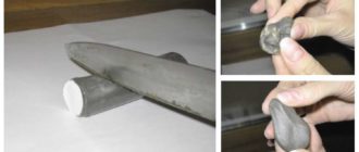
During the welding process, under the influence of strong heat and heavy mechanical load, the working part of the electrode changes with the formation of a mushroom-shaped thickening, and the surface becomes contaminated with metal oxides. An increase in the actual diameter of the electrode at constant current and compression force means a decrease in current density and specific pressure.
As a result, the heating intensity in the welding contact is greatly reduced, and metal compaction becomes more difficult and welding may be of poor quality. In addition, contamination of the surface of the electrodes can cause an increase in contact resistance, overheating and even melting of the surface of the sheets. It is generally believed that wear-related increases in diameter by more than 10% are no longer acceptable.
Such electrodes must be cleaned with a file, a special device, or sharpened.
Pre-compression time
The pre-compression time is understood from the start of applying pressure to the start of heating. It must be sufficient so that the compression mechanism has time to bring the electrodes together and develop pressure to a given value. This parameter does not have a direct effect on thermal processes during welding. To improve performance, this parameter should be reduced as much as the speed of the compression mechanism allows.
Forging time
The forging time (tnp) is determined by the duration of the already welded point being under the compressive influence of the electrodes. This parameter affects the cooling rate of the metal after welding, since after heating, under conditions of close contact between the electrodes and the part, heat from the welding zone is transferred especially quickly to the electrodes.
When welding hardening steels, accelerated cooling can cause cracks and forging time should therefore be reduced.
However, in all cases, the pressure should not be released before some time necessary for complete hardening and strengthening of the core. Otherwise, the sheets deformed during welding, trying to elastically return to the initial position, can destroy the core that has not yet cooled. With increasing thickness, the forging time increases, since the volume of heated metal and the cooling time increase.
We also recommend that you familiarize yourself with:
Flash butt welding mode parameters.
Source: http://svarak.ru/kontaktnaya-svarka/rezhimyi-tochechnoy-svarki-parametryi/
Adjusting the current in a semi-automatic welding machine - Metals, equipment, instructions
One type of joining and cutting metals is electric welding. It is performed using welding machines and electrodes or special wire. The required current strength depends on the diameter of the electrode, the type of work - welding or cutting and the thickness of the metal. Therefore it needs to be regulated.
Despite the proliferation of new inverter devices, many people still have old devices in their garages and sheds that require manual adjustment. It cannot be done in the same way as adjusting the transformer current in a semi-automatic welding machine or inverter, in which this work is performed by electronics.
Design and principle of operation of a welding transformer
A transformer for electric welding, like any other, consists of three main elements:
- Primary winding. Voltage is applied to it. In home devices, the coil is connected to a 220V network; in production, to reduce current consumption, 380V is supplied to it.
- Secondary winding with voltage 45-110V. An electrode and ground are connected to it, and in welding rectifiers, diodes or a diode bridge.
- Magnetic core. This is the core on which the coils are wound. It consists of a large number of transformer iron plates and can be toroidal, rectangular and W-shaped.
High-power devices are additionally equipped with starting and protective equipment, as well as fans.
There are three modes of operation of transformers:
- Idle mode. In it, the device operates during a break during the welding process.
- Work mode. This is welding or cutting metal.
- Short circuit mode. Appears when the electrode is stuck.
The welding transformer current is adjusted in operating mode.
The main disadvantage of such a device is the variable output voltage. This makes it possible to use only carbon electrodes and weld only ordinary metal. Welding stainless and high-alloy steels requires special electrodes and the use of a welding rectifier.
Information! Unlike conventional transformers, welding machines have an operating mode similar to short circuit mode. Therefore, to reduce heating, they are wound with a wire of larger cross-section.
Welding rectifier
Using constant tension produces a better quality seam. It allows, in addition to conventional types of processing, to perform argon-arc welding and other types of work.
Information! In addition to single-phase devices, such devices are made into three-phase ones. This increases power with load distribution across three phases and provides a smoother, ripple-free output voltage.
Welding rectifiers are distinguished by the type of installed rectifier units:
- With two diodes. Instead of one secondary winding, two are wound and the diodes are connected according to a circuit with a common midpoint.
- With a conventional diode bridge. In single-phase devices, a conventional bridge is installed, consisting of four diodes; in three-phase devices, a Larionov bridge is installed, consisting of six.
- Transistor. Rarely found due to too powerful output transistors.
- Thyristor. A type of diode devices, but instead of diodes, thyristors and a control system are installed. The adjustment is carried out by changing the opening angle of the thyristor and the effective voltage value.
- Inverter. Modern electronic devices for individual use. The current is adjusted using control knobs or buttons located on the front panel.
These transformers are manufactured in different capacities and are designed to connect different numbers of posts:
- Single-post. Can only be used by one welder. Adjustment is carried out both at the workplace and inside the device. The current-voltage characteristic can be steeply falling (soft), flat falling (hard), and also switchable.
- Multi-post. They have sufficient power to connect several (up to 9) posts. The characteristic is only rigid; the welding process can only be adjusted at the workplace using ballast resistors.
Semi-automatic welding
The semi-automatic machine consists of two main components:
- Wire feed unit. It feeds the wire into the welding zone and is additionally equipped with a shielding gas supply device.
- Arc power device. It is used as a welding rectifier or inverter.
Reference! The current of the semi-automatic device is regulated in the device feeding the arc.
Device parameters
The main parameters are output current and voltage, as well as dynamic characteristics.
Output current and voltage
The main parameter of the welding machine is the output current. The diameter of the electrodes and the thickness of the metal depend on it. In individual devices it reaches 200A. Since the output voltage is important only when the arc is ignited, in modern inverter devices, in order to reduce power consumption and rectifier dimensions, this parameter is reduced as much as possible, and arc ignition is provided by additional built-in devices.
The output voltage in single-station devices is 45-65V. In large machines designed for simultaneous operation of several welders, the output voltage can reach 110V.
Dynamic response
When the distance from the end of the electrode to the part changes, the length of the arc and its resistance change. Therefore, no less important is the dynamic or current-voltage characteristic - the dependence of the current on the arc length:
Steeply falling, or soft. As the current increases in a device with such a characteristic, the voltage drops, which limits its increase. This provides a more stable arc as the distance to the part changes.
In homemade devices of low power, the soft characteristic is ensured by the internal device - the primary and secondary windings are wound on different parts of the magnetic circuit. Due to the design features without additional resistance, they could work with electrodes of a specific diameter for each device.
In higher power devices, the dynamic response is softened by ballast resistances. These methods can be combined.
Sloping or rigid characteristic. With a hard characteristic, the voltage does not change, but the current changes accordingly when the arc length changes. Large multi-post devices or automatic devices that maintain a constant distance between the electrode and the workpiece have such parameters.
Adjusting the welding machine
There are different ways to control the current of a welding machine.
With moving windings and core
The stiffness of the characteristic depends on the magnetic coupling between the primary and secondary coils. To change it, it is necessary to change the distance between the primary and secondary windings or the size of the air gap in the magnetic core. To do this, the core or coil is mounted on a special nut, and the screw is equipped with a handle. When it rotates, the nut is screwed on and the moving part changes its position, which leads to a change in current.
This method is used in alternating voltage devices, as well as those additionally equipped with diode bridges.
Core magnetization with constant voltage
Another control method is to magnetize the core with a constant voltage. The magnetized core increases the resistance to the magnetic flux created by the primary winding. This reduces the arc current.
Interesting! The operation of a magnetic amplifier is based on a similar principle. This device was used in electric drive control systems before the advent of thyristor converters.
Ballast resistances
One of the most common and simplest adjustment methods is to use ballast resistance:
- Active ballast. It consists of several wire or tape resistances that are switched if necessary to change the electric welding current. Can be used with all types of devices. In homemade low-power devices, instead of a set of resistances, a nichrome spiral or snake is used.
- Inductive ballast. This is a choke, the inductance of which can be changed, if necessary, by changing the number of turns or the size of the air gap in the magnetic circuit. Installed in series with the secondary winding before the diode bridge.
Thyristor control
This adjustment is used in rectifiers in which some or all of the diodes are replaced by thyristors. When the opening angle changes, the effective voltage value and current of the device changes. The angle is controlled by variable resistors or more complex circuits.
The disadvantage of this scheme is the transformation of constant voltage into pulsating voltage, which deteriorates the quality of the seam.
Important! When the opening angle is more than 90°, the amplitude value drops, which worsens the arc ignition process.
Adjusting the primary winding
The adjustment of the welding transformer currents through the primary is carried out by a thyristor switch - two thyristors connected back-to-back in parallel using a variable resistor connecting the control terminals or a small transistor circuit.
Adjustment of the primary thyristor switch allows you to control alternating voltage devices.
All these adjustment methods are losing their significance along with old devices and the spread of new, inverter ones. They are more economical, lighter, and some stores offer to exchange your old reel welder for a new one. But while the old devices are in operation, knowledge of how the welding current in the transformer is regulated will allow you to perform welding work more efficiently.
Source: https://spb-metalloobrabotka.com/regulirovka-toka-v-svarochnom-poluavtomate/
Welding modes - selection and parameters
When the conversation turns to such a concept as welding modes, it is necessary to realize that this is a fairly large set of various parameters, which in turn determine the conditions of the welding process. And in order for the quality of the final result to be only positive, you need to choose these same parameters correctly. And although experts conditionally divide them into primary and secondary, all of them, without exception, affect the quality of the weld.
The main parameters of the welding mode include:
- The amount of current installed on the welding machine.
- Its gender (fixed or variable) and polarity (direct or reverse).
- Welding arc voltage.
- Diameter of the electrode used.
- Speed of the welding process.
- Number of passes to fill the weld.
The secondary ones include:
- The quality of cleaning of welded workpieces.
- The shape of the joined edges.
- Type of electrode: its brand, type of coating, coating thickness.
- The angle of inclination of the electrode relative to the welding surface.
- Its position (top, bottom or side).
- How the joint is located (horizontally, vertically, at an angle).
Welding mode parameters
It should be noted that most often welders pay attention to the main parameters and their mutual relationship, but at the same time they do not lose sight of the secondary ones.
For example, the diameter of the electrodes is selected depending on the thickness of the metal parts being welded, the position of the joint, as well as the shape of the prepared edges.
And although there are tables that determine the diameter of the consumable relative to the thickness of the workpieces, it is very important to take into account the position of the electrode itself during the welding process.
Electrodes with a diameter larger than 4 mm cannot be used for ceiling welding. The same applies to the multi-pass process, because it is in this case that the root weld may not penetrate properly.
Welding current
As for the current strength, here too there are several provisions regarding the choice of welding parameters. The thing is that the more intense the current, the higher the temperature inside the weld pool. And this affects the rate of metal melting and the productivity of the welding process itself. And this is correct, but with some reservations.
- With increased current and a small diameter of the electrode, overheating occurs in the welding zone of the workpieces. This is already a decrease in the quality of the seam. Plus intense splashing of metal inside the bathtub. Often this mode leads to burnout.
- If the current strength is reduced, then this is a guarantee of lack of penetration, because at low current the arc becomes unstable. And with such an arc, the welding process often breaks down. This is the reduction in connection quality.
- If an electrode with a large diameter is selected without taking into account the thickness of the workpieces, the current density deteriorates. The reason is low cooling of the metal in the welding zone.
Not the last word in such a concept as the choice of welding mode is the polarity of direct current. With reverse polarity of the current, the penetration depth is 40% greater than with direct polarity. When using alternating current for welding, it must be taken into account that the penetration depth when using it is 15% less than when using constant current. And this is at the same current value.
Welders themselves with extensive experience set the welding current experimentally. They simply pay attention to the stable state of the arc, to its stable combustion. Beginners can use various tables or formulas. For example, one of the formulas that determines the current strength depending on the diameter of the consumable. It can be used if welding uses an electrode with a diameter of less than 3 mm.
I=30d
Welding process speed
The choice of arc welding mode also depends on the speed of movement of the electrode. This parameter is directly related to the thickness of the parts and the thickness of the seam. Its ideal value can only be considered when the area where the molten metal joins the edges of the parts is free of undercuts, burns and lack of penetration. The seam itself is a transition of a uniform shape without sagging or undercuts.
The higher the speed, less metal will get into the bath, the edges will not heat up to the required temperature, hence the lack of fusion of the seam, which will quickly crack. If the speed is lower, nodules are formed that interfere with penetration. The optimal mode is when the width of the seam is twice the diameter of the consumable.
Arc length
Another parameter that affects arc welding modes. Arc length is the distance from the end of the electrode to the top surface of the edge being welded. The ideal option is if this distance is the same along the entire length of the weld. But that's not all. It is important to choose this distance correctly.
Experts believe that the length of the arc should be equal to the diameter of the consumable used. Unfortunately, only experienced welders can withstand such a distance. Therefore, there are certain deviations. For example, for an electrode with a diameter of 3 mm, it is better to keep the distance to the edge within 3.5 mm.
Electrode angle
The position of the electrode relative to the welding plane affects the width of the weld and its penetration depth. It is considered optimal if the rod should be located perpendicular to the connection of the workpieces. But this is practically impossible, because the welding tool of the welding machine moves along the joint. Therefore, the electrode is positioned either tilted forward or tilted backward.
In the first case, the seam becomes wide, and the penetration depth decreases. This happens because the molten metal is forced out to the front of the weld pool. In the second case, on the contrary, the molten metal is pushed to the rear of the bath. Therefore, the depth of the joint is well welded in this way, but the width of the seam is noticeably reduced.
By the way, the angle of inclination of the workpieces being welded has exactly the same effect on the quality of the seam.
If welding is performed on parts that are located at a certain angle, and the electrode itself moves from top to bottom, then a thickened layer of molten metal forms under the consumable. And this is an increase in the width of the seam and a decrease in the depth of penetration.
If the movement is made from bottom to top, then there is much less molten metal under the arc, which makes it possible to deepen the welding, but at the same time obtain a small seam width.
Experts recommend installing the workpieces at a slight angle, no more than 10°. In this way, metal spreading along the seam can be avoided, which will ensure the quality of welding. In this way, lack of penetration and undercuts can be avoided.
As you can see, manual arc welding modes are a set of measures based on the correct selection of certain parameters. Even the slightest deviation can lead to a decrease in the quality of the connection between two metal workpieces.
Source: https://svarkalegko.com/tehonology/rezhimy-svarki.html
Adjusting the current in a semi-automatic welding machine - Metalworker's Handbook
- Date: 06/12/2015
- 734
- : 54
Many types of welding equipment are expensive. The most convenient is a semi-automatic welding machine (SPA), which is multifunctional. The operating principle of a semi-automatic welding machine depends on its correct settings. Semi-automatic welding machines are universal and practical. Their use in the domestic economy is widespread.
Scheme of an inverter semi-automatic welding machine.
In everyday life and industry, SPA is used to produce effective welding. Performing welding work using semi-automatic machines is based on high-quality welding of non-ferrous and ferrous metals without the use of additional elements. The welding process uses carbon dioxide or argon, which are protected by the use of a melting type of solid wire.
What are the requirements for the preliminary welding stage?
Basic semi-automatic welding modes.
Powerful welding equipment should be used while observing safety precautions. The spa is dangerous because it can cause electric shock. Incorrect use of the equipment may result in fire.
Incorrect configuration of a semi-automatic machine can lead to damage to some parts of its design. All of these preliminary steps must precede mechanized welding using this device. The idle mode of operation of the spa should not be associated with the delivery of voltage to the tip of the hose.
Before starting work, the grounded terminal is connected to the SPA. Then you should adjust the power parameters, as well as the welding wire feed speed. Setting options are provided according to the thickness and type of metal. There are tables indicating all welding parameters using SPA. They can be found in specialized literature describing the welding process.
List of possible malfunctions of the welding inverter.
Setting up the SPA involves mandatory monitoring of the voltage on the welding wire, that is, the electrode. The control process of a semi-automatic device assumes appropriate logic based on the following circuit for removing and supplying voltage to the SPA:
- Removal from microswitch.
- Engine supply.
- It flows to the reverse winding of the motor.
- Receiving it with a sleeve and gas cutoff.
Having studied all the safety requirements and special instructions in books, they proceed to working with a semi-automatic device. First, you should connect it to the electrical network and press the power button. The trigger of the device should be pressed when the face is protected by a special mask.
First you need to cut off the excess wire, leaving about 3 mm, counting from the end of the burner. After the arc appears, you should slowly move the torch to the future connection. When lumps form on the end of the wire, it is necessary to increase the wire feed speed into the apparatus.
How to set up a semi-automatic machine for high-quality gas supply?
Inverter front panel diagram
You can adjust the dosage of the amount of inert or carbon dioxide coming from a gas cylinder or reducer automatically or manually. With the correct settings of the semi-automatic welding machine, the electric arc will burn perfectly evenly. This allows the welding process to be carried out virtually without splashes.
It is necessary to ensure that the metal of the connection does not boil. This is achieved by correctly setting up the semi-automatic welding machine by ear. The gas hisses quietly during welding, producing a uniform noise.
An experienced welder ensures that the gas is blown and not blown. In this case, the arc should not break, so you need to move the wire forward. If intermittent hissing sounds occur and the wire melts rapidly, which occurs faster than the burner moves, it is necessary to reduce the feed speed.
Sometimes it is necessary to adjust all the settings for high-quality welding for several days until an even, stable arc is obtained.
It has a stable sound and a characteristic crackling sound. The type and amount of gas supplied plays an important role in the process of regulating the welding machine. For example, a porous and weak weld will result from insufficient gas flow.
What semi-automatic devices allow you to make adjustments?
Image 1. Schematic diagram of the SPA.
The operation of any spa is associated with the presence of a welding transformer in its design. The susceptibility of welding current switches to wear requires the constant participation of a master regulating the welding process. For this purpose, you can use a contactless relay, which is the switching board of the transformer device. This is due to the presence of a significant resource in terms of switching.
The adjustment process is based on the use of an electrical signal transmitted through a circuit (IMAGE 1). The semi-automatic control system has an action logic that allows blocking the switching of each stage of the transformer device during a welding load. However, this can be a common reason associated with broken switches.
The simplest device that allows you to customize the SPA circuit is a throttle. It has several stages, which can be switched when the inductance level decreases or increases. Another possible device for adjusting the device is an active throttle.
Power supply circuit for a semi-automatic welding machine.
When using this device, you will not need to use mechanical switching, which will ensure smooth adjustment of inductance parameters. This adjustment mechanism allows you to correctly configure the process associated with the transfer of materials.
Manual arc welding, which allows connections to be made using a welding inverter, is also typical for semi-automatic machines. Therefore, an important PV parameter is provided for it. It is a percentage designation showing the permissible operating time of the semi-automatic device. This indicator will allow you to maintain the level of wear resistance of the equipment for a long time, ensuring its operation at a high-quality level.
Before using the semi-automatic device, the current value must be adjusted so that the metal does not become burnt. However, determining the exact current value is difficult.
This point requires, before starting welding, to carry out training using a metal plate into which the wire is inserted. You can change the welding current using a rheostat.
This is the most effective means of adjusting the welding arc for different metal thicknesses.
Recommendations for correctly setting up a semi-automatic welding machine
Semi-automatic welding process.
The welding current indicator should be set in the settings depending on the thickness of the metal being welded and the diameter of the wire used as an electrode. This dependence is relatively standard, so the value of the indicator does not fluctuate much.
Typically, the device body or its instructions should contain information about the possible values of the welding current indicator. In certain cases, the table with indicators may be missing for some reason. Then experts recommend using the following current indicators for welding metal, taking into account its thickness, indicated in brackets:
- 20 - 50 A (1-1.5 mm).
- 25 - 100 A (2-3 mm).
- 70 - 140 A (4-5 mm).
- 100 - 190 A (6-8 mm).
- 140-230 A (9-10 mm).
- 170 - 280 A (11-15 mm).
Torch for semi-automatic welding with a consumable electrode: 1 - mouthpiece, 2 - replaceable tip, 3 - electrode wire, 4 - nozzle.
This list is associated with a fairly large range of indicators that are united by a common trend. Its principle boils down to the fact that to weld the thickest material, a greater welding current is required. This indicator is determined by the diameter of the wire used.
If you use thin wire during the welding process, it allows you to configure the semi-automatic machine to operate using less current. If you use thicker welding wire, more current will be required. Due to the inertia of mechanics, the movement of the welding wire occurs slowly, gradually accelerating.
You can regulate the motor current using a special switch. The welding current must be sufficient to ensure complete braking of the wire. The current is adjusted in the semi-automatic welding machine using a trimming rheostat. Subsequent braking of the wire occurs after a certain time.
What results can you get from setting up a spa?
Submerged arc welding diagram.
As a result of the adjustments made, the welding wire should not spread or melt. This occurs when a very small current value is selected. You will need to increase the voltage to check the result. If the wire has spread well, then a “drop” should appear on the back of the metal. This will mean that everything is normal.
If, after using the welding wire, a slight depression is formed, then the “drop” will hang on the other side. This is due to the choice of the welding current value above the norm. You should take another piece of metal to conduct the experiment at a lower voltage level.
If a hole appears instead of a wire, then this is due to the choice of too high a current value. You should use another workpiece to carry out semi-automatic welding at a lower voltage level. For training welding, workpieces coated with zinc cannot be used, since it evaporates and releases harmful substances. They can harm the human body.
After preliminary training, you should finally make sure that the current settings are correct. In this case, the metal workpiece must be clamped with sufficient force. Only after this can you proceed to the main welding, not forgetting about safety precautions. Before welding, you should be dressed in a welder’s suit and protect your face with a special mask.
Source: https://ssk2121.com/regulirovka-toka-v-svarochnom-poluavtomate/
Semi-automatic welding: technology, correct settings and instructions for beginners - Machine
For welding metals, a laser beam, torch flame or plasma can be used, but one of the simplest and most compact options for devices for performing this type of work is a semi-automatic device.
To ensure that the metal seam is as smooth as possible and protected from oxidation, welding metals in this way is best done using shielding gas.
Semi-automatic welding for beginners is difficult only in the first minutes of mastering. To speed up the learning process as much as possible, you should study the basic rules for handling such a device in advance.
Semi-automatic welding machine: operating principle
In order not to “kill” the device when using a semi-automatic welding machine. To avoid injury, you should know about the safety rules and the operating principle of the device.
The semiautomatic welding machine consists of:
- housing containing a powerful transformer;
- hose for supplying current and gas to the burner;
- cables for connecting to ground and the electrical network;
- wire feed mechanism.
Also, for semi-automatic welding, you will need to purchase a reel with a special welding wire and a cylinder of carbon dioxide.
The operating principle of the semi-automatic device is as follows:
- The welding current is supplied to the torch simultaneously with the shielding gas.
- The torch uses a welding wire as an electrode, which is fed automatically using a special mechanism.
- An electric arc is formed between the product being welded and the wire, which melts the metal in a protective gas environment, which allows you to obtain a high-quality weld without oxides.
The basic safety rules when working with semi-automatic welding machines are as follows:
- the body of the welding machine must be grounded;
- it is prohibited to use the device even with minor mechanical damage or any other malfunctions;
- in case of significant interruptions in work, be sure to disconnect the device from the electrical network and turn off the supply of protective gas;
- do not work near flammable and explosive substances;
- Use a protective mask and gloves while working.
As soon as the basic principles of working with a semi-automatic machine are mastered, you can begin practical work.
Semi-automatic welding: first experience
To gain practical experience, it is recommended to first practice on unnecessary metal scraps before proceeding with complex work that requires highly qualified welders.
For practical work you need to prepare:
- welding machine;
- gloves;
- protective mask;
- gas cylinder.
The first thing you need to do is set up the welding machine. Correctly adjusted strength of the supplied current will allow you to make a welding seam perfectly smooth and without breaks.
This parameter directly depends on the thickness of the metal being welded, so before starting work, you must read the instructions for the electrical device. Which should indicate the amperage recommended by the manufacturer for a certain thickness of the parts being welded.
Selecting welding modes
You should also make the right choice of the welding wire feed speed, which is regulated by a special mechanism.
The optimal diameter of the wire for welding is 0.8 mm, but when working with very thin metal, you can install a 0.6 mm electrode so that at a reduced current the metal is melted without fading the arc.
If possible, it is better to purchase Italian wire for semi-automatic welding. Imported analogues are of higher quality, but the cost of such products will be several times higher.
Despite the higher cost, such an electrode is more suitable for beginners because it is easier to obtain the desired result, even with insufficient experience in handling an electric welding machine.
instructions: setup.
Cylinder with reducer
In order to protect the welding site from exposure to oxygen, shielding gas is supplied. The cheapest option for using shielding gas is to purchase a carbon dioxide cylinder with a reducer.
A reducer with a pressure gauge must be installed to monitor the pressure of the supplied gas. To carry out high-quality welding of metals in a shielding gas environment, it is enough to set the working pressure to about 0.2 atmospheres.
Protective mask
To protect your eyesight, semi-automatic cooking should only be done using a protective mask, for example, Chameleon. Modern products have a special adjustment in their design, which allows you to configure the protective mechanism in such a way that it provides high-quality protection only during arc burning.
When the plasma combustion process dies out, the window of the mask will be transparent enough to allow you to continue working without removing the protective device.
Such welding helmets will be especially convenient for novice welders; in outdated models, the protective glass was too shaded, which made the welding process very inconvenient, due to poor visibility of the weld after the arc has died out.
Welding technology
When all the preparatory work has been carried out, it is necessary to connect the “ground” to the metal being welded. If you have to work with small parts, then welding is done on a metal table, to which the corresponding conductor is connected.
If there is no table, then the work can be carried out on a horizontally located metal sheet with a thickness of at least 2 mm, to which the “ground” of the welding machine is connected.
Before starting the welding process, it is also necessary to adjust the amount of protrusion of the welding wire from the nozzle. It is recommended to install such a protrusion no more than 5 mm. If the wire protrudes more significantly before starting welding work, it must be shortened using wire cutters.
Before making a continuous weld, it is recommended to position the parts to be welded as close as possible and to carry out spot welding in at least two places by striking the electrode against the metal at the joint. This is necessary to ensure the immobility of the parts being welded.
If you need to weld one sheet of metal onto another, then in this case you can use clamps to securely fasten the welded parts. Once the immobility of the parts is ensured using any of the listed methods, you can begin making the weld.
To weld parts, an arc igniter is made and the metal is melted at the junction of the metals to form a seam. If during the first attempts to weld parts the arc does not ignite stably, it is necessary to increase the current supplied by the welding machine.
For proper arc formation, it is necessary to briefly touch the wire to the metal parts to which the “ground” is connected. Then tear off the wire to the minimum possible distance to form a stable electric arc. In this way, the seam is welded from one edge to the other, gradually moving the arc over the surface of the parts being welded.
- thin metal connection.
- welding thick metal for beginners.
Aluminum welding
The use of shielding gases in semi-automatic welding makes it possible to perform high-quality connections of aluminum parts in this way. Welding aluminum is a rather complex process even for an experienced specialist; it will be even more difficult for novice welders to complete such work.
How to semi-automatically cook aluminum parts:
- the surface of the welded parts is cleaned from the oxide film;
- the workpieces are heated in a furnace or using a gas burner;
- the welding machine is switched on to high-frequency alternating current mode;
- a cylinder with argon or argon-helium mixture is connected;
- The arc is ignited and its length is maintained in the range of 12-15 mm.
In this way, parts made of this low-melting metal are welded. To perform the work, you will need to purchase aluminum products as filler wire. And to ensure stable wire feeding, the device must be equipped with a larger diameter nozzle.
Conclusion
For novice welders, you learned how to weld semi-automatically with carbon dioxide correctly from this article. To consolidate the information received, it is recommended to immediately begin practical exercises and carry out a trial connection of parts using this method. Lessons will allow you to quickly master a semi-automatic machine at home.
It is recommended to start welding aluminum and other non-ferrous metals only after welding of ferrous metals is well mastered. This article tells you how to cook stainless steel with a semi-automatic machine.
(5
Source: https://regionvtormet.ru/stanki-i-oborudovanie/svarki-poluavtomatom-tehnologiya-pravilnaya-nastrojka-i-instruktsiya-dlya-nachinayushhih.html
Adjusting the welding current on the primary winding
Each control method can have a positive effect on the operation of the welding unit, but each method also has its own disadvantages, which it is advisable to know and be able to avoid unpleasant situations. The welding process is a responsible procedure, therefore it determines almost any deviation from the norms.
Using special regulators:
- The operating current is adjusted,
- The magnetic flux changes.
Therefore, the current regulator for a welding machine performs an important function and the main methods of regulation are: magnetic shunting, mobility of windings, as well as various types of chokes.
Methods for adjusting welding parameters
If you connect to the taps that are made on the second winding of the transformer, then there is the possibility of stepwise regulation of the electric current. When using this method, the number of turns changes, thus reducing or increasing the current.
But there are disadvantages to this method, which lie in the minimum adjustment ranges. And the control device will have to be of decent dimensions in order to withstand serious electrical overloads. You will also have to use powerful switches that can withstand high currents.
The secondary winding takes up significantly greater loads than the secondary winding, so this device wears out quickly. To improve the performance of this design, thyristors are used, which are integrated into the primary winding.
With the help of such a device, you can configure the welding machine, and it is very simple to do. To make a current regulator for a welding machine, you need to correctly select the resistances and other elements included in the circuit of this device.
Current regulator circuit for a welding unit
The thyristors in the device are installed in parallel so that they are turned on by the current generated by the two transistors. When the regulator is connected to the circuit, the thyristors are in the closed state, and the capacitors receive the charge due to variable resistance.
And when the capacitor reaches a certain voltage, the discharge current moves. After the transistor, the thyristor opens, connecting the load.
By changing the resistance of the resistor, it will be possible to adjust the connection of the thyristors. In this regard, the total current on the original transformer winding changes.
To achieve an increase or decrease in the adjustment range, the resistance of the resistor changes in the desired direction. If transistors are not available, the use of dinistors is an acceptable condition.
Regulator circuit with dinistors and transistors
A current regulator for a welding machine is mounted not only on transistors designed to produce an avalanche voltage, but also using dinistors.
This element must be connected with its anodes to the resistance terminals, and with its cathodes it must be connected to the other two resistors. Transistors of models P416, GT308 are used for regulators of welding devices, but there is also the possibility of connecting low-power transistors with similar characteristics.
Variable type resistors can be used SP-2, and MBM are used as permanent elements. In this case, it is necessary to select a resistance that will have a suitable operating voltage.
In order to properly assemble a control device for a welding machine, you need to use a textolite base with a thickness of 1.5 - 2 millimeters, then the installation process will be more convenient.
It is necessary to ensure that all parts involved in the circuit are insulated from the housing, since short circuits and an increase in temperature are possible. Serious overloads can lead to negative consequences and failure of both individual elements and the entire device.
If all the rules were followed when assembling the control device, and the parts were selected according to optimal parameters, then the regulator does not need to be adjusted.
But before using the device in full, you need to check the operation of the transistors included in the circuit, because they may not withstand the avalanche mode.
Thanks to the stable operation of the device, welding machines will be able to work normally with different materials and structures being welded.
Share a link to this material with your friends on social networks (click on the icons):
Source: https://steelfactoryrus.com/regulirovka-svarochnogo-toka-po-pervichnoy-obmotke/
Setting the parameters of a semi-automatic welding machine
The semi-automatic welding machine is a very convenient device for working at home and in small workshops. You can work with it in any conditions, no special preparation of the workplace is required, it is compact almost like a regular inverter.
Unlike manual arc welding, it does not require a highly qualified welder to work with it. Correct setting of a semi-automatic welding machine allows even a low-skilled welder to perform high-quality work.
Depending on the type of material being welded and its thickness, it is necessary to correctly set the wire feed speed and shielding gas. Next, the welder needs to move the torch evenly along the seam, and a high-quality weld will be obtained. The whole difficulty lies in the correct selection of welding parameters for a specific material.
Equipment capabilities
To properly configure a semi-automatic welding machine, an understanding of the welding characteristics is required; it is also necessary to understand the features of the semi-automatic machine.
Semi-automatic welding machines allow you to work with almost any metals and their alloys. They can weld non-ferrous and ferrous metals, low-carbon and alloy steel, aluminum and coated materials, are capable of welding thin metals up to 0.5 mm thick, and can even weld galvanized steel without damaging the coating.
This is achieved due to the fact that flux, flux-cored wire or shielding gas, as well as welding wire can be supplied to the welding area, and the supply occurs automatically, everything else is done as in manual arc welding.
Semi-automatic welding machines are produced in different classes, but they all consist of:
- control unit;
- power supply;
- welding wire feed mechanism with reel;
- welding torch;
- power cables.
In addition, there must be a cylinder with a reducer and inert gas (carbon dioxide, argon or mixtures thereof), and a funnel for flux.
The wire feed mechanism consists of an electric motor, a gearbox and feed or pull rollers.
Recommendations in the instructions
Before starting work, it is necessary to reliably ground the welding machine and only then begin setting up. The semi-automatic welding machine must be connected to a gas cylinder system with protective gas.
It is necessary to check the presence of welding wire in the spool, if you need to reload it and stretch it to the torch handle. The gas supply speed is of great importance in the welding process.
Therefore, it also needs to be installed. Gas equipment has gearboxes indicating gas consumption in liters. This is very convenient; you just need to set the required flow rate within 6-16 liters.
The operating instructions for the device provide recommendations on how to properly set up a semi-automatic welding machine, what current to use to weld a specific metal, and at what speed to feed the wire.
The instructions should contain special tables in which everything is described. If you set all the parameters in accordance with them, then everything should work out.
In practice there may be difficulties. The quality of semi-automatic welding is influenced by many parameters. If the supply network does not meet the standards, then the power source will produce voltage and current that is not what is needed, the parameters will be unstable.
The temperature of the medium, the thickness of the metal, its type, the condition of the surfaces being welded, the type of seam, the diameter of the wire, the volume of gas supply and many other factors affect the quality of semi-automatic welding.
Tables of recommended welding conditions are given for certain conditions, which cannot always be achieved. Therefore, when welding semi-automatically, many adjustments are made experimentally.
Of course, the recommended values are initially set, then the welding parameters are fine-tuned.
Setting current and wire feed speed
First of all, the strength of the welding current is set, which depends on the type of material being welded and the thickness of the workpieces. This can be found out from the instructions for the semi-automatic machine or found in the relevant literature.
Then the wire feed speed is set. It can be adjusted stepwise or smoothly. With stepwise adjustment, it is not always possible to select the optimal operating mode. If you have the opportunity to choose a device, buy a semi-automatic welding machine with continuously adjustable wire feed speed .
The control unit must have a forward/reverse wire feed mode switch. When all the settings have been made in accordance with the operating instructions for the semi-automatic machine, you need to try working on a draft sample with the same parameters. This must be done because the recommendations are average, and in each individual case the conditions are unique.
At a high wire feed speed, the electrode simply will not have time to melt, there will be large deposits or shifts on top, and at a low speed it will burn out without melting the metal being welded, the weld bead will sag, and depressions or breaks will appear.
Adjusting parameters
Adjustment of current or voltage depends on the thickness of the workpieces. The thicker the product being welded, the greater the welding current. In simple semi-automatic welding devices, the current adjustment is combined with the wire feed speed.
In professional semi-automatic machines, the adjustments are separate. The correct setting can only be determined experimentally by making an experimental seam on a test piece. The roller should be of normal shape, the arc should be stable, without splashes.
Some semi-automatic models have inductance adjustment (arc settings). With low inductance, the arc temperature drops, the depth of metal penetration decreases, and the seam becomes convex.
This is used when welding thin metals and alloys that are sensitive to overheating. With high inductance, the melting temperature rises, the weld pool becomes more liquid and deeper. The seam bead becomes flat. Welding in this mode is used for thick workpieces.
The welding wire feed speed switch in models capable of working with different diameters requires additional adjustment taking into account the specific thickness of the wire.
Even after fully studying the manufacturer’s recommendations, it is not always possible to obtain the desired operating mode of the semi-automatic machine.
Having set the optimal settings for welding a workpiece today, it may turn out that the next day they will become suboptimal because the quality of the network has changed or the position of the product on the workbench has changed.
That is, setting the modes is a constant and individual process because it also depends on the work style of the welder himself.
Common mistakes
An error in the settings of the semi-automatic welding machine is indicated by a distinct crackling sound. Loud clicks indicate that the solder feed rate is low. It is necessary to increase the feed speed until the cracking noise disappears.
Heavy spattering of metal is often observed. This is due to an insufficient amount of insulating gas in the weld pool area. It is necessary to increase the gas supply and adjust the semi-automatic gearbox.
There are lacks of penetration or burns in the seam. This is due to the arc voltage being too low or too high and can be adjusted by setting the voltage or inductance.
The uneven width of the weld bead is associated with the speed of movement of the torch and its position relative to the seam, that is, it is associated with the welder’s working technique.
If you follow the manufacturer's recommendations and understand the processes occurring in the weld pool and how to adjust them, you can perform quite complex types of welding work at home.
Source: https://svaring.com/welding/teorija/kak-nastroit-svarochnyj-poluavtomat
Selecting welding mode: current, arc length, polarity
Selecting welding mode: current, arc length, polarity
To get a high-quality and reliable welding seam, you need to understand which electrodes are best to use and which mode of manual arc welding to choose. In addition, it is important to take into account other equally significant factors, such as: the composition and thickness of the metal, the dimensions of the workpiece being welded, and for what purposes it will be used in the future.
In general, the welding mode is selected according to many factors and after analyzing the data obtained. In this article from the website mmasvarka.ru we will consider the main factors that, to one degree or another, can influence the choice of mode.
Welding mode selection
So, what factors influence the choice of one or another mode of manual arc welding. First of all, this is:
The main criteria when choosing a mode for MMA welding, of course, is determined by the burning nature of the welding arc, the stability of which depends on how correctly the current strength is selected for some specific electrodes. The higher the current, the larger the diameter of the electrodes you can weld thick metal. In simple words, high currents ensure better arc burning and good heating of the metal.
You should know that when a seam is applied vertically, the current strength changes less than when applied horizontally, by about 15%. For ceiling seams, the value of the welding current will be even less, by about 20%. Very often, values regarding the current strength are on the packaging with electrodes. In addition, you can determine what current strength to set on the welding machine from the table below with the values.
Average welding current (A):
- Electrode diameter (1.6 mm) - electrode with rutile and basic coating (30-55 A) and (50-75 A);
- Electrode diameter (2 mm) - electrode with rutile and basic coating (40-70 A) and (60-100 A);
- Electrode diameter (2.5 mm) - electrode with rutile and basic coating (50-100 A) and (70-120 A);
- Electrode diameter (3 mm) - electrode with rutile and basic coating (80-130 A) and (110-150 A);
- Electrode diameter (4 mm) - electrode with rutile and basic coating (120-170 A) and (140-200 A);
In turn, in order to correctly determine the diameter of the electrode, it is necessary to take into account the thickness of the metal, the welding method and the geometric location of the seam. So, for example, for each electrode its own “own” current value is selected. If you greatly increase its performance, you can easily burn through the metal or, conversely, not achieve a high-quality and reliable weld.
Selecting current depending on the diameter of the electrodes
Thin metal, no more than 1 mm thick, is welded with 1 mm electrodes, and the current strength is set to the minimum possible values, in the range of 10-30 A. When welding thicker metal, up to 2 mm, electrodes of a slightly larger diameter are used, 1. 5 or 2 mm. The current strength for welding with these electrodes is set in the range of 30-50 A.
A 3 mm electrode is used to weld metal up to 4 mm, and the current on the inverter is set to 60-120 A. For welding metals over 10 mm thick, much thicker electrodes are already used - 4 and 5 mm. For their normal use, the welding machine must be set to a current of more than 120 A.
Welding arc length
To achieve a good connection, it is important to correctly determine not only the diameter of the welding electrodes, but also the length of the welding arc. There is a common belief among welders that the length of the arc should correspond to the diameter of the electrode used. However, it is very difficult for novice electric welders to maintain such a short arc without it being pulled to the side.
Therefore, when selecting this value, you should proceed from the current strength and diameter of the electrodes used for welding:
- For electrodes up to 2 mm - the arc length is 2-2.5 mm;
- For 3 mm electrodes, the arc length is 3.5 mm;
- For 4 mm electrodes, the arc length is 4.5 mm;
- For 5 mm electrodes, the arc length is maintained within 5.5 mm.
In addition, it is important to take into account the optimal welding speed, which also largely depends on the current strength and other features. Here you can follow one proven path, and with the correct selection of welding speed, the welding seam should be approximately twice the diameter of the electrode used.
Reverse or straight polarity?
To select the welding mode with a coated stick electrode, it is equally important to determine which operating mode to switch the welding inverter to. There are two of them, reverse and direct polarity.
In order to weld thin metal with an inverter and not burn it later, it is recommended to switch the welding machine to reverse polarity, when the flow of electrodes is directed not at the workpiece, but at the electrode. Conversely, if you connect the inverter in direct polarity, you can improve the quality of welding, for example, when you need to weld thick metal.
To connect the inverter in reverse polarity (for welding thin metal):
- A positive terminal is connected to the holder with the electrode, and a negative terminal is connected to the workpiece.
To connect the inverter in direct polarity (for welding thick metals):
- A negative terminal is connected to the holder with the electrode, and a positive terminal is connected to the workpiece.
To choose the right welding mode with an inverter, you need to take into account many different nuances. Only in this way will it be possible to achieve a high-quality and reliable welding joint that will withstand heavy loads.
Source: https://mmasvarka.ru/vybor-rezhima-svarki.html
Welding lessons: How to set up a argon arc machine for TIG welding?
Previously, we talked about how to select an electrode, gas and other consumables. In this article we will continue to consider the welding process, or more precisely, working with a tig argon arc machine. For convenience, we will immediately highlight the issues that will be addressed in this material:
For clarity, we use specific models and blanks. We will weld stainless steel, and the tig machine will be the reliable and easy-to-use FUBAG INTIG 200 DC Pulse. In addition to the main functions, the equipment has a pulse welding function.
As for consumables, the example shown uses an argon cylinder, WL 20 electrodes (for direct current) and filler rod.
Preparing the argon arc apparatus for operation
All components are at hand. Putting it all together:
-
We install the reducer on the gas cylinder
-
Connect the gas hose to the reducer
-
Connect the bayonet connector of the torch to the negative connector
-
Connect the control cable to the five-pin connector on the front panel
-
Lastly, connect the ground cable to the positive connector.
The device is almost ready for use, now let’s move on to assembling the tig burner:
1. Install the collet holder first
2. Carefully insert the collet into it
3. Screw the shank (not all the way)
4. Install the ceramic nozzle
5. Insert the tungsten electrode
6. Adjust the electrode extension
7. Tighten the shank thoroughly.
Once everything is done, we set the gas flow depending on the location and nozzle diameter. For a nozzle with a diameter of 10 mm, a gas flow rate of 10 l/min is quite suitable.
Attention! In addition to the apparatus itself and the burner, the workpieces also require preparation. By cleaning them from rust, oxide film and other contaminants, you will take care of the quality of welding. For degreasing, you can use acetone, white spirit or another solvent. The filler rod is also sanded and degreased.
Setting up a tig machine from A to Z
Almost all metals are welded with straight polarity (minus on the electrode). The only exception is welding of aluminum and its alloys. A striking example of an alloy can be copper alloys with a significant aluminum content. The use of alternating current is mandatory for them.
So, let's set up FUBAG INTIG 200 DC Pulse:
-
On the control panel we set the welding method - TIG.
-
Set the gas pre-purge to 0.5 seconds.
-
We set the ignition current - 25% of the operating current (A).
-
We fix the rise time to the operating current - 0.2-1.0 seconds.
-
Set the welding current (A) (see table below)
-
We set the time until the crater filling current (decay in seconds)
-
Select the value of the crater filling current in amperes
-
The last parameter will be the gas purging time after welding (sec)
The parameters that relate to crater welding are selected depending on the thickness of the metal.
This table provides general recommendations for selecting welding current for the most commonly used metals and thicknesses. This will help you get your bearings as you prepare to get started.
Table. Setting up an argon arc apparatus depending on the type of metal and thickness
| Type of metal | Metal thickness, mm | Type of current | Current ¸A |
| Steel alloys | 1,0 | DC | 20 — 30 |
| 1,5 | DC | 40 — 60 | |
| 2,0 | DC | 70 -90 | |
| 3,0 | DC | 100 — 120 | |
| 4, 0 | DC | 120 — 140 | |
| Aluminum | 1-2 | A.C. | 20 — 60 |
| 4-6 | A.C. | 120-180 | |
| 6-10 | A.C. | 220-230 | |
| 11-15 | A.C. | 280-360 |
Why is monitoring current strength more important than other parameters? During TIG welding, you can burn through the workpiece by setting too high a current. A low value will not allow the metal to melt, which will negate all attempts to weld the part.
Correct starting and welding with a TIG torch
The parameters are set and it's time to start. Owners of this welding machine model have two options:
-
Use contact ignition
-
Use the high frequency ignition function
The latter will prevent metal burning in case of incorrectly set parameters when setting up the argon arc welding machine. It will protect the metal from tungsten inclusions and allow you to independently control the distance to the part from the moment you start working.
And now the most important thing is how to operate the burner correctly? Most experienced welders weld from right to left. During the process without filler material, the electrode should be positioned almost perpendicular to the surface to be welded. If filler material is present, then it is enough to maintain a small angle (15-20 degrees).
Attention! To prevent the weld metal from oxidizing, it is necessary to ensure that the end of the filler rod is constantly in the protective gas zone.
The welding process is completed by filling the crater. Crater welding is the final section of the weld seam, the length of which is reduced to zero. From the point of view of the quality of the welded joint, it is necessary to exclude the formation of a crater in the final part of the weld. For this purpose, the device provides a smooth current reduction mode.
To illustrate all of the above, experts have prepared a special video:
Tell your friends
Source: https://fubag.ru/tips/uroki-svarki-kak-nastroit-argonodugovoy-apparat-dlya-tig-svarki/
How to set up a welding machine for electrode welding?
In everyday life, the need to weld objects periodically arises. Very often such a need arises in the private sector. For a large number of jobs, you can turn to experienced welders, but for small jobs it is better to use an inverter welding machine.
This is the simplest, most affordable and convenient type of welding. It is available for everyone to work with. To do this, you need to know the principles of the welding process.
Welding with an inverter has become a breakthrough in the field of welding machines, since outdated transformers are quite heavy and difficult to use. The advantage is that with inverter welding, spatter occurs less than when welding from a transformer.
An inverter is a welding machine that allows you to connect sheets of metal using an electric discharge. It has a distinctive feature: it has low weight and maximum capabilities , thanks to which it can perform work previously carried out by heavy and complex devices. The weight of the device depends on its power (from 3 to 7 kg).
You can transport it using a handle or strap. Cooling is provided by ventilation holes in the case. This device consumes electricity, which is directed only to the operation of the arc , and it carries out the welding process itself.
The device is insensitive to voltage changes. If there are constant fluctuations, you should pay attention to the required voltage, which is indicated in the inverter’s passport.
Handles and control indicators are located on the surface of the device :
- turns on and off with a toggle switch;
- the voltage and current values are set using knobs on the front panel;
- the panel has indicators informing about power supply and device overheating;
- The outputs (“+” and “-“) are located on the front of the panel.
Additionally, the set contains 2 cables . One of them ends with a holder for the electrode, and the second has a clip in the form of a clothespin for securing the product. The device is connected via a connector located on the rear panel of the device.
Principle of operation
An inverter is an electronic device that runs on electricity. When old welding machines are turned on, a strong and huge jolt of electricity occurs, which may result in a power outage.
The inverter has storage capacitors that store electricity and ensure uninterrupted operation of the network. They gently ignite the arc of the inverter.
It is worth paying attention to the fact that electricity consumption depends on the diameter of the electrodes. The larger it is, the greater the consumption. In this regard, in order not to burn household appliances, before working with the inverter, it is necessary to calculate the maximum possible amount of electricity that will be consumed by the device.
It is worth considering that for each electrode diameter the minimum current strength , i.e. if you try to reduce the current strength, the weld will not work. If the current increases, it will work, but the electrode will quickly burn out.
The arc comes from the connection between the metal portion of the electrode and the metal being welded. The electrode and metal begin to melt under the influence of arc temperature . The molten parts in its place form a bath. The electrode coating melts, part of which goes into a gaseous state and blocks the bath from oxygen. The other part of the coating (in a liquid state) protects the metal from air during welding and during the cooling process.
After welding and cooling of the metal, the liquid part is slag, covering the seam from the outside. After cooling, the slag is removed by tapping with a hammer.
The electrode melts during the welding process. To prevent the arc from going out, you need to maintain its length , i.e., the distance between the metal and the electrode. This can be done by inserting the electrode into the welding site at the same speed and exactly along the seam joint.
With a short arc (about 1 mm), the metal is heated over a small area, and the weld comes out convex. At the point where the seam and metal meet, a defect such as an undercut (a parallel dimple near the seam) may appear. It reduces the strength of the seam.
A long arc is unstable, poorly protected from air, almost does not heat the metal, and the weld is not fully deep. The normal arc size is from 2 to 3 mm . A constant gap of this size will form a normal seam with good penetration.
How to properly weld metal with an inverter
To work with welding, the following protective elements are required:
- Gloves are made of rough material, but in no case are rubber.
- Welding helmet with a filter, which is selected depending on the value of the welding current. It is more convenient to use a “chameleon” mask, since the filter installed in it recognizes the arc and is darkened to suit its size. It is worth noting that at low temperatures the filter does not have time to work in time, and at temperatures below -100 degrees this mask will not protect.
- Clothing, which should be made of natural dense and non-flammable material, cover the neck and arms.
- Closed shoes made of genuine leather and thick soles.
It is necessary to prepare a safe place for welding :
- Free space, absence of everything unnecessary.
- Good lighting.
- The work is performed standing on a wooden floor, which protects against electric shock.
After this, you need to adjust the welding current (depending on the thickness of the metal and parts) and select an electrode (2-5 mm). Usually the strength of this current is indicated on the device body. Electrodes must be selected based on the brand of welding materials. Next, connect the ground terminal to the surface to be welded.
, the metal should be prepared before starting work . Use a metal brush to remove rust from the edges, which need to be treated with a solvent (gasoline, white spirit). It is important to prevent the presence of grease and paint materials on the edges.
For beginners, it is better to make a seam in the form of a roller on a metal sheet with a large thickness. The sheet must be placed horizontally on the table. A straight line is drawn on it with chalk as a guide in the work, along which the roller will be laid. To start welding, you need to ignite the arc. You can do this in 2 ways:
- chirping;
- tapping.
You can strike and hold the arc in both ways. Next comes the welding process itself, which produces a weld seam. Metal deposits on top of the seam must be removed by tapping with a small hammer or hard object. The ability to control the length of the arc will provide excellent results.
The beauty of the seam is influenced by:
- electrode inclination angle;
- diagram of transverse and longitudinal movements;
- speed of electrode movement.
Welding such seams (slanted and ceiling) is a rather complex process. This is due to the fact that even molten metal is subject to the law of gravity. He is constantly pulled down, which causes difficulties. Beginning welders will need to spend a lot of time learning how to do this.
There are 3 technologies for vertical seam welding:
- Triangle. Used when connecting parts with a thickness of no more than 2 mm. Welding occurs from bottom to top. The liquid metal is on top of the solidifying one. It flows down, thereby covering the suture roller. The flowing slag does not interfere, since it moves along the solidified bath, which exits at a certain angle. Externally, the weld pool looks like a triangle. In this method, it is important to move the electrode accurately to completely fill the joint.
- Herringbone. This type of welding is suitable for gaps between workpieces equal to 2-3 mm. Along the edge from the depth towards you, you need to use an electrode to melt the metal to the entire thickness of the workpiece and, without stopping, lower the electrode to the gap. After melting occurs, do all this along the other edge. You need to continue from the bottom to the top of the weld. This results in a uniform arrangement of molten metal in the gap space. It is important to prevent the formation of undercut edges and metal leaks.
- Ladder. This method is used when there is a large gap between the workpieces being joined and little dulling of the edges (or its absence at all). Welding is carried out in a zigzag manner from one edge to the other from bottom to top. The electrode stops at the edges for a long time, and the transition is made quickly. The roller will have a small cross-section.
Welding polarity
Melting of the metal during the welding process is carried out under the influence of the heat of the arc. It forms between the metal and the electrode when they are connected to opposite terminals of the welding device.
There are 2 options for performing welding work: direct and reverse polarity .
- In the first case, the electrode is connected to the minus, and the metal to the plus. There is a reduced introduction of heat into the metal. The melting point is narrow and deep.
- In the second case, the electrode is connected to the positive, and the metal to the negative, resulting in a reduced heat input into the product. The melting point is wide, but not deep.
When choosing welding, it is necessary to take into account that the network element connected to the plus heats up more. Thick metal is welded with direct polarity, and thin metal with reverse polarity.
Tips for dummies
- do not neglect protective equipment;
- Before performing work, it is worth practicing to prevent mistakes;
- welding must be performed with the minimum recommended amperage;
- do not forget to beat off the slag;
- to reduce the deformation of the product, you need to secure the parts during the welding process;
- follow instructions and recommendations.
In addition to the fact that welding can be used to connect parts, it can also be used to cut them . To do this, you need to increase the current and cut off the part or corners. It’s just not possible to do it exactly.
By using this guide, you can gradually improve your skills and use inverter welding without any problems in the future. The main thing in this matter is practice.
Source: https://rem-serv.com/kak-nastroit-svarochnyy-apparat-dlya-svarki-elektrodom/