How to solder LEDs: varieties, procedures and connection methods
Lamps have long been used as the main operating element of lighting systems. They have gone through many stages of structural and functional development, but today they are experiencing a crisis due to fierce competition with diode crystals. Modern LED lamps have become widespread due to their performance qualities, which, however, also have negative aspects of use.
In the process of repairing such a device, the user may encounter the problem of updating failed crystals. The question of how to solder an LED logically arises if one of the crystals has burned out. This will be indicated by the presence of a black dot on the yellow surface of the element.
And if, under the conditions of a factory layout, the restoration operation is carried out mechanically in an in-line mode, then at home it will be necessary to organize conditions for manual soldering.
What types of LEDs are there?
In most cases, ordinary users of lighting devices deal with output LEDs and a more advanced design based on SMD crystals. The first are introduced into the circuit using two conductors and most often serve as a means of indicating various equipment - for example, in a car they perform the tasks of a warning light, operating from a 12 V source.
Directly in lighting and illumination systems, SMD diodes in leadless packages are more often used. Due to the fundamentally different electrical layout on the board, this particular lighting device is more likely to cause complications.
How to solder SMD LEDs? Fastening is carried out not through special holes, as is the case with the same output devices, but directly to the surface with an overlay. For this purpose, special contact pads are provided, which must be soldered one by one, maintaining the correct placement of the diodes on the board.
On the one hand, this approach simplifies the technology of mounting crystals, but on the other hand, it requires more attention from the performer, since one has to deal with elements of miniature sizes, compactly placed in a small space.
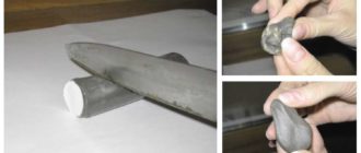
As part of the preparatory process, several tasks must be resolved. of these consists of cleaning the working surface and, if necessary, dismantling the burnt-out diode. Old elements are best removed with low-power 25 W soldering irons after tinning the tip to the required size, which will allow for convenient thermal cutting. Next, special attention is paid to the surface.
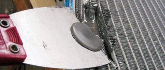
Varnishes and all kinds of technical coatings must also be removed mechanically - for example, by cleaning them with a construction knife. Now another question - how to solder LEDs onto aluminum boards? In this case, it would be a good idea to prepare a special flux for a specific metal or use universal tin-lead solder. As for choosing a soldering iron, there will be no need for high power.
You can give preference to compact models with heating up to 250 °C.
Angle connection technique
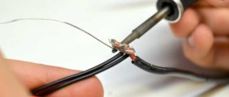
Often, when creating complex lighting systems from several parallel lines, wires are connected in different areas. To make this connection easier, corner soldering with a 90-degree angle is used. Plus and minus are fixed on the contact pads of two adjacent diodes. What’s also important is that this method allows you to easily connect RGB strips using four wires.
The corner joint does not affect the quality of the backlight in any way, but allows you to implement a variety of configurations for splicing LED strips. Problems can only be caused by the presence of a special casing for tapes with a protection class higher than IP68. For example, how to properly solder LEDs filled with silicone or compound? In this case, the initial cleaning procedure becomes more complicated.
At a minimum, it will be necessary to form technical holes in the coating for current-carrying conductors. Soldering is then carried out using them.
Among the advantages of LED devices, one of the main places is their optimization, which is also reflected in the minimum requirements for consumables during installation. Nevertheless, sometimes the inclusion of connectors in electrical circuits justifies itself.
How to solder LEDs with such elements? Soldering in this case acts as an auxiliary means of ensuring a reliable connection between the wires, and the connectors form a kind of reinforcing internal frame. The optimal width of the connector is 8-10 mm.
At the first stage, it is necessary to create a structural connection by making the required number of contacts on the board, and then proceed directly to soldering.
It should be taken into account that a connection to a connector does not always provide an advantage from the point of view of future operation of the LED. Firstly, connection points with such fittings are more prone to burning, and also contribute to the rapid heating of the emitter.
Secondly, the glow may deteriorate, which is reflected in a decrease in brightness.
How to solder LEDs onto a board with a connector to eliminate such negative effects? It is advisable to abandon copper conductors and perform the soldering itself in a continuous manner, which will eliminate the risk of the formation of oxidation sites.
Overlap joining technique
A method that does not involve the use of auxiliary conductors at all. This technique is recommended for use with strip lights and other diode devices, the crystals of which are placed compactly on a small board.
For example, how to solder SMD LEDs with an overlap soldering iron? To begin with, the ends of the LED lines are cut so that the contacts are close to each other. The current-carrying conductors are lubricated with flux, after which tin plating can be applied until a silver coating is formed.
Then one piece with a wire part is overlapped onto another piece, strictly observing polarity. A short period of gentle heating is enough to form a strong connection.
Soldering procedure
Whatever connection method is chosen, the general soldering technology involves performing a universal set of actions, including the following:
- Solder or flux is used to tinning the current-carrying contacts that are planned to be connected.
- The ends of the current-carrying wires, which have already been tinning, are applied to the connection point on the board or other conductor.
- Now the main operation is connection. How to solder LEDs manually? It is enough to point the soldering iron tip at the target area of the connection and hold it there for 3 to 5 seconds. As a result of rapid heating, a reliable joint is formed.
- After soldering, it is advisable to keep the docking unit isolated for several hours without any external influences.
Features of soldering with a hairdryer
Soldering using this method is usually considered as an alternative method to classical soldering. It is chosen for various reasons, the main one of which is the ability to remove heat from the crystal while minimizing the risk of thermal damage. But this method is only suitable for designs with a surface connection on the board.
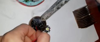
For example, how to solder SMD LEDs with a hairdryer? The heating process is organized on the back side of the board. The performer's task is to ensure sufficient heating of the connection area so that the solder on the front side reaches a state that allows the diode to be securely fixed.
Theoretically, this action can be accomplished with an iron and a low-power gas burner, but to preserve the structure and the board itself, it is still safer to use a special heat gun.
Soldering errors
Even if the externally created connection seems correct, the device may not work correctly if technological errors were made. Most failures are associated with improper distribution of solder or melt, which results in typical defects such as lack of fusion.
How to solder LEDs to avoid this result? Both the solder and the melt must be strictly controlled during thermal exposure. The uniformity of the layers of the connecting coating must be maintained.
To identify such violations in the structure, scanning with a thermal imager is performed at the non-destructive testing stage.
Conclusion
Soldering LED lamp crystals is a simple operation that any home craftsman can do. However, there are a lot of technological subtleties and details, ignoring which can nullify even the efforts of a diligent craftsman. It is necessary to take into account not only the conditions for soldering as such, but also the connection configuration itself.
For example, how to solder SMD LEDs with a group arrangement of crystals? To successfully perform such an operation, at a basic level, you will need to determine the electrical circuit for installing diodes on the board.
It is necessary to calculate the circuit and only after that proceed to element-by-element connection of crystals in accordance with the planned configuration of the lighting device.
Source: https://FB.ru/article/469530/kak-payat-svetodiodyi-raznovidnosti-poryadok-deystviy-i-sposobyi-soedineniy
Types and arrangement of LED strips in 2020
In the article you will learn about what types of LED strips there are and what their structure is.
Kinds
For convenient use, such lamps are produced in flexible strips with an average length of 5 meters. But if desired, through extensions, this size can be safely increased.
Depending on its purpose, the LED strip can be:
- Single color - red, blue, yellow, green or just white.
- Multicolor - here the color palette is wider, and all the bulbs can light up at the same time.
Multi-colored LED strips
The latest products require a special remote control that can control the glow.
Also, LED strips have another classification:
By LED type – SMD 3028 and SMD 5050.
According to the density of light bulbs on the strip - 30, 60, 120, 240 LEDs per 1 linear meter.
In terms of power - from 7.2 W to 28.8 W per 1 linear meter.
By color.
According to the degree of moisture resistance - P 20, IP 65 and IP 68.
Depending on where exactly such a lamp will be used, it is worth selecting the characteristics of the tape.
Device
As of 2020, there is a wide variety of LED strip devices. But their essence is the same - LEDs are located on adhesive tape, which are connected to each other by current-carrying paths. In order for such a lamp to work, it is also equipped with diodes and transistors.
tape device
You can purchase such a tape in a roll of 5 meters, and then it is cut into pieces of the required length. BUT! Here it is worth considering the fact that each such segment has its own boundaries. Typically, manufacturers mark the cutting location with a dotted line.
Thus, instead of 5 meters, you may end up with many pieces 5 cm long, where each piece will contain 3 LEDs and 1 limiting transistor. The reverse side is equipped with double-sided tape, which greatly simplifies installation. If necessary, you can choose models where the LEDs are located not in 1 row, but in 4. This will directly affect the intensity of lighting.
Each tape has its own marking, where the width and height parameters are indicated. For example, SMD3028 – 3.0 – width, 2.8 – height.
To control the lighting, during the installation process, the strip is connected to the power supply, and if an RGB product is used, then a controller is also needed. This device not only provides switching on and off, but also helps regulate the color of the lamps and their intensity.
Source: https://slarkenergy.ru/osveshhenie/svetilniki/led-lenty-vidy.html
Soldering SMD parts without a hair dryer
Everyone understands how you can, using a regular 40-watt EPSN soldering iron and a multimeter, independently repair various electronic equipment with lead-out parts. But such parts are now found, mainly only in power supplies of various equipment, and similar power boards, where significant currents flow and high voltage is present, and all control boards are now based on SMD element base.
Radio components on the SMD board
So what if we don’t know how to dismantle and solder back SMD radio components, because then we won’t be able to carry out at least 70% of possible equipment repairs on our own. Someone who is not very familiar with the topic of installation and disassembly may say that for this you need a soldering station and a soldering hair dryer, various nozzles and tips for them, no-clean flux, such as RMA-223, and the like, which is usually not available in a home craftsman’s workshop.
Soldering Station
I have at home a soldering station and a hair dryer, nozzles and tips, fluxes, and solder with flux of various diameters. But what if you suddenly need to have your equipment repaired, on the road to order, or while visiting friends? Is it inconvenient to disassemble and bring the defective board home, or to a workshop where the appropriate soldering equipment is available, for one reason or another? It turns out there is a way out, and it’s quite simple. What do we need for this?
What you need for good soldering
- 1. Soldering iron EPSN 25 watt, with a tip sharpened into a needle, for mounting a new microcircuit.
- 2. Soldering iron EPSN 40-65 watts with a tip sharpened to a sharp cone, for dismantling a microcircuit, using Rose or Wood alloy. A soldering iron with a power of 40-65 watts must be turned on via a Dimmer, a device for regulating the power of the soldering iron. You can have one like the one in the photo below, very convenient.
- 3. Rose or Wood alloy. We bite off a piece of solder from the droplet with side cutters, and place it directly on the contacts of the microcircuit on both sides, if we have it, for example, in a Soic-8 package.
- 4. Dismantling braid. It is required to remove solder residues from the contacts on the board, as well as on the chip itself, after dismantling.
- 5. SKF flux (alcohol rosin flux, crushed into powder, dissolved in 97% alcohol, rosin), or RMA-223, or similar fluxes, preferably based on rosin.
- 6. Flux Off flux residue remover, or 646 solvent, and a small brush with medium-hard bristles, which is usually used in school, for painting in art lessons.
- 7. Tubular solder with flux, 0.5 mm in diameter (preferably, but not necessarily this diameter).
- 8. Tweezers, preferably curved, L-shaped.
Wiring of planar parts
So, how does the process itself work? Read something here. We bite off small pieces of Rose or Wood solder (alloy). We apply our flux liberally to all contacts of the microcircuit.
We put a drop of solder on Rose, on both sides of the microcircuit, where the contacts are located. We turn on the soldering iron and set it using a dimmer, the power is approximately 30-35 watts, I don’t recommend it anymore, there is a risk of overheating the microcircuit during dismantling.
We pass the tip of a heated soldering iron along all the legs of the microcircuit, on both sides.
Dismantling using Rose alloy
In this case, the contacts of the microcircuit will close, but this is not scary, after we dismantle the microcircuit, we can easily remove excess solder from the contacts on the board and from the contacts on the microcircuit using the dismantling braid.
So, we took hold of our microcircuit with tweezers, along the edges, where the legs are missing.
Typically, the length of the microcircuit, where we hold it with tweezers, allows us to simultaneously move the soldering iron tip between the tips of the tweezers, alternately on both sides of the microcircuit, where the contacts are located, and slightly pull it up with tweezers.
Due to the fact that when melting Rose or Wood alloy, which have a very low melting point (about 100 degrees), relative to lead-free solder, and even ordinary POS-61, and moving with the solder on the contacts, it thereby reduces the overall melting temperature of the solder .
Dismantling microcircuits using braid
And thus the microcircuit is dismantled without dangerous overheating. On the board we have the remains of solder, Rose alloy and lead-free, in the form of sticky contacts. To bring the board back to normal, we take the dismantling braid; if the flux is liquid, you can even dip its tip into it, and place it on the solder “snot” that has formed on the board. Then we heat it from above, pressing it with the tip of a soldering iron, and run the braid along the contacts.
Soldering braided radio components
Thus, all the solder from the contacts is absorbed into the braiding, transferred to it, and the contacts on the board are completely cleared of solder.
Then the same procedure must be done with all the contacts of the microcircuit, if we are going to solder the microcircuit into another board, or into the same one, for example, after flashing it using a programmer, if it is a Flash memory chip containing the BIOS firmware of a motherboard, or monitor, or what or other technology.
This procedure must be performed to clean the microcircuit contacts from excess solder. After this, we apply the flux again, place the microcircuit on the board, position it so that the contacts on the board strictly correspond to the contacts of the microcircuit, and there is still some space left on the contacts on the board, along the edges of the legs.
For what purpose are we leaving this place? So that you can lightly touch the contacts with a soldering iron tip and solder them to the board. Then we take a 25-watt EPSN soldering iron, or a similar low-power one, and touch the two legs of the microcircuit located diagonally.
Soldering SMD radio components with a soldering iron
As a result, the microcircuit turns out to be “stuck” and will not budge, since the melted solder on the contact pads will hold the microcircuit. Then we take solder with a diameter of 0.5 mm, with flux inside, bring it to each contact of the microcircuit, and simultaneously touch the tip of the soldering iron tip, the solder, and each contact of the microcircuit.
I do not recommend using solder of a larger diameter; there is a risk of adding “snot”. Thus, we have solder “deposited” on each contact. We repeat this procedure with all contacts, and the microcircuit is soldered into place. If you have experience, all these procedures can actually be completed in 15-20 minutes, or even in less time.
All we have to do is wash off the remaining flux from the board with solvent 646, or Flux Off cleaning agent, and the board is ready for tests after drying, and this happens very quickly, since the substances used for rinsing are very volatile. 646 solvent, in particular, is based on acetone.
Inscriptions, silk-screen printing on the board, and solder mask are not washed off or dissolved.
The only thing is that dismantling a microcircuit in a Soic-16 or more multi-pin package in this way will be problematic due to difficulties with simultaneous heating and a large number of legs. Happy soldering everyone, and fewer overheated microcircuits! Especially for Radio circuits - AKV .
Forum
Discuss the article Soldering SMD parts without a hair dryer
Source: https://radioskot.ru/publ/konstruktiv/pajka_smd_detalej_bez_fena/13-1-0-1155
Soldering SMD components with a soldering iron
Sometimes it happens that you urgently need to solder an SMD element, but there are no special tools at hand. Just a regular soldering iron, solder and rosin. In this case, it is difficult to solder a miniature SMD element, but it is possible if you know certain features of such soldering.
I use some skills that I haven’t seen described anywhere, so I decided to share them ( at the end of the note - see the video of the process ). SMD housing - 0805.
It is impossible to make the sting not tremble
Not a single person is able to make sure that a tool (any tool - not just a soldering iron ) does not tremble in his hands. Once upon a time I read about masters who paint miniature paintings or murals. The technology they use in their work was described there. Its essence is that it is necessary to coordinate the movements of the hand with the beats of the heart. The inevitable actually occurs from heartbeats .
There is no need to fight trembling - it is useless. You need to learn to adapt to it.
Bird's beak technique
When a bird builds a nest, inserting another branch, it makes short and multiple movements with its beak. Even if it is necessary to correct a twig that has already been inserted into the nest, the bird performs each action by making several small and precise movements. In truth, these movements are not always accurate, but in total they still give the desired result.
The mistake of many beginners is that when soldering they try to make a long and continuous movement. It's useless. The secret is that you need to make short movements (ideally they are coordinated with the heartbeats, but you don’t need to specially concentrate on this - over time it should work out by itself).
Soldering an SMD element in three stages
The difficulty of soldering SMD elements with a conventional soldering iron is to hold the part with tweezers .
Those. At the very beginning of soldering, the main attention should be concentrated on the strength of the hand holding the tweezers. It is also important here to choose the correct viewing angle in order to clearly see how smoothly the part lies in its place.
It doesn't hurt to know one little secret.
At the very beginning, it is enough to just “ grab ” the part slightly. No need to try to solder it on the first side right away! Good soldering requires a shift of attention to the soldering process itself - concentration on the tweezers is lost
Thus, first we only grab the part from one end.
Having grabbed the part, we get rid of the tweezers and solder the second side of the part. And only then do we return to the final soldering of the first side.
Do not forget that the areas for the element on the board must be level . If there was solder there, you need to carefully remove the excess before soldering, otherwise the part will remain “skewed” after soldering.
So, when the part is stuck, it is no longer possible to move it (unless you overheat or apply noticeably great effort). This allows you to take a break from holding it, and concentrate on soldering from the other end , and then return to the first.
Thus, soldering occurs in three stages:
- "Picking" of the part
- Soldering the opposite end to the “stuck” end
- Return to soldering the “stuck” end
Below is a video that I recorded when I was finalizing the video and audio output for the old FUNAI
(see the article FUNAI tvr 1400a mk7 - how to make a video output).
All the tools used are simple and crude, including a homemade brush made from fishing line (with which I wash the soldering area with alcohol ).
Rosin - ordinary, “pebble”. Soldering iron - 25 watts. BY THE WAY! The best soldering iron for “delicate” parts is one on which the rosin “smoke”, but does not have time to completely boil over on the tip for about 7 seconds. If the rosin boils away within 2-3 seconds, then the soldering iron tip is too hot and can damage the SMD element.
acceptable to be captured , even with some minor blemishes (touching an adjacent pad, dripping of excess rosin), which was facilitated by the camera, which required me to hold the tools almost at arm's length.
Nevertheless, this soldering is normal and the essence of the technique was demonstrated here. I recommend expanding the video to full screen and setting the quality to “Full HD” in the video settings.
Source: https://rem-serv.com/payka-smd-komponentov-payalnikom/