How to solder LEDs correctly
Nowadays, the most common type of lighting is LED. Thanks to the huge number of advantages, such light sources have taken their place in almost any area of human activity.
LEDs
Without them it is no longer possible to imagine electronic equipment, modern toys and many other attributes of modern society. LED strips are especially often used as lighting devices today. Therefore, it is very important to know how to solder diodes with your own hands in order to independently repair failed radio-electric parts at home or replace them correctly.
We remember the school physics course
In order to solder LEDs (for example, SMD type), you need to know what some of the signs on the circuits mean. Namely:
- "U". This letter on all electrical diagrams indicates voltage. It is measured in V (volts);
- "I". Under this designation lies the current. It is measured in A (amps);
- "R". This letter means the electrical resistance of the circuit elements. This indicator is measured in Ohms (ohms).
All of the above values reflect Ohm's law, which is described by the following formula:
In addition, you need to understand that under the letter “P” is power, which is measured in W (watts). Power is determined by the following formula:
The decoding of these values must be known in order to correctly solder LEDs into any circuits and boards.
How are diodes connected?
Before you start soldering LEDs (for example, SMD type), you need to know how they are connected to the circuit or in series to each other (if we are talking about LED strips).
Note! LEDs are most often connected to a network with a voltage of 12 or 9 V. But usually the devices are designed for a current consumption level of 0.02 A (20 mA).
Current stabilizer
The ideal option for LEDs is to connect them through a current stabilizer. It should be remembered that such stabilizers will cost slightly more than single LEDs (for example, SMD type). This must be taken into account when independently assembling radioelectric devices.
In order to power yellow and red LEDs, a voltage of 2.0 V is often required. At the same time, to power blue, green and white LEDs - 3.0 V. The
following example will help to understand this issue:
- a 12 V battery is available, as well as 0.02 A and 2.0 V LEDs;
- the simplest solution here would be to supply a voltage of 2.0 V to each diode;
- in this case, the extra 10 V will need to be extinguished using a resistor. It is also often called resistance;
- Using Ohm's law, we calculate the resistance value (R = U/I). As a result, we get R = 10.0/0.02 = 500 Ohm;
- Also, in order to protect the resistance from excess heat, it is necessary to calculate its power. The result will be P = 10.0 * 0.02 A = 0.2 W.
For greater reliability, it is necessary to take a resistance of slightly larger capacity.
Note!
As the resistance power increases, its overall dimensions will naturally increase. Knowing the above aspects, you will be able to connect the LEDs to the battery correctly using a resistor for this. The main thing here is to strictly observe the polarity of the parts used.
What is needed for work
Many radio electronics enthusiasts who practice self-assembly of various devices are interested in the possibility of independently soldering LEDs (for example, SMD type) for circuits.
If you have the proper tools and knowledge, creating such circuits yourself is quite possible. For this type of work you will need:
- tester;
- calculator;
- medical tweezers (optional, but recommended);
- soldering iron
Tester
Note! When working with LEDs, especially when testing them, you need to be careful not to direct the beam coming from these elements into your eyes.
As you can see, the set of tools here is small and can easily be found in any home. With this kit, you will be able to correctly solder diodes, both in the circuit and in series as part of the LED strip.
The structure of diode elements and how to solder them
A standard LED is a glass bulb with an approximate diameter of 5 mm, to which lead legs are attached.
Diode appearance
The short leg represents the negative terminal, and the long leg represents the positive terminal.
If you mix them up when soldering, the LED will not light up. The process of soldering such elements has the following algorithm:
- We place each diode in its own place;
- soldering areas should be treated with ordinary tin or flux;
- after that, apply a soldering iron to them for a couple of seconds;
- After this, the remaining legs can simply be bitten off.
After you have soldered all the LEDs to the circuit, you need to check your handiwork.
To do this, they must be connected to power. If all the diodes light up, this means that you did everything correctly. In addition, there are LEDs, which, for ease of working with them, are produced in the form of special strips. They can be cut and connected to each other, which makes it possible to use them for lighting rooms, shop windows, etc.
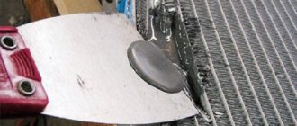
Places for cutting LED strips and soldering wires
Such tape should only be cut in appropriate places. If you cut in another place, you will simply ruin the product by damaging the LED connection. Such pieces need to be soldered using special contact pads that end these sections.
Note! You can solder LED strips using a soldering iron with a power of 40 V.
As a flux, you should use a special solution that looks like a gel. Remember that the ends of the wires in this situation should be well tinned. You can also use special devices to create contacts between pieces of LED strip - connectors. But they are quite expensive, so they are rarely used.
Soldering Features
After we have refreshed our school knowledge and the basics of connecting LED elements, and also found all the necessary tools, we can begin to directly work with the parts.
LEDs can be connected in series. The important thing here is to know how to do it correctly.
Note! In order to solder diodes in series, they should be selected with the same parameters.
The resulting chains of LEDs can be used in a wide variety of devices and purposes. Most often, they are used to organize various types of lighting (open or closed) for premises, as well as vehicles. When installing such chains, you should remember that the voltage in the car's electrical network will be higher than 12 V (14-14.5 V). The machine's power supply is not characterized by constant voltage. To suppress possible interference, special voltage stabilizers are needed.
Chip KREN8A
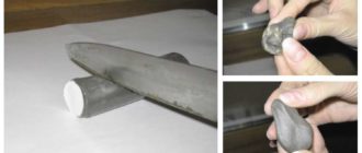
Independent assembly of voltage stabilizers is possible on the basis of KREN8A and K142EN8A microcircuits for a 9 V network. KREN8B and K142EN8B microcircuits are suitable for a 12 V network. A
small-sized soldering iron is suitable for soldering this element. Its tip should heat up to 260 degrees.
Note! The duration of the soldering process for each point should be 3-5 seconds.
To ensure that the soldering itself went correctly, you need to know the following rules and recommendations:
- If you don’t have even minimal soldering experience, you need to practice first. Otherwise, there is a high risk that the LEDs will not work or will even deteriorate. To improve your skills, you should use wires with different cross-sections;
- It is imperative to use standard tin-lead solder and flux for aluminum;
Flux for aluminum
- Wires that have not been covered with oxides must be tinned immediately after exposure. To do this, you need to take a small amount of solder and heat it on the soldering iron tip. Then we touch the rosin with it and run it along the exposed sections of the wires. As a result of such manipulations, the solder will spread into a thin film;
- sometimes tinning is not allowed. Then the wire should be placed on an aspirin tablet and heated with a soldering iron. Heating lasts 3-5 seconds.
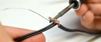
LED soldering process
Knowing these rules, you can correctly solder the LEDs in series.
Another soldering option
In addition to conventional LEDs, there are chips that are mounted in LED strips. The most common LEDs today are SMD type.
SMD LED
This circuit element is a leadless component. SMD does not have traditional copper lead wires. Therefore, such elements are connected using printed circuit board tracks. Soldering is also used to connect the SMD diode to the board.
It is necessary to solder track tracks and contact pads to them.
Soldering such a circuit component is not difficult, since for this you can use a low-power type of soldering iron with a capacity of 10-12 W.
Therefore, you can quite conveniently and quickly solder each contact in series separately.
Soldering SMD components
There are situations when it is necessary to desolder SMD components to replace or test them. In such a situation, in order to prevent the element from overheating, you need to warm up all its terminals at the same time.
If such a need with SMD components happens often, then it makes sense to purchase a special set of soldering iron tips. These tips should have two or three small branched ends.
They are very easy to work with SMD as the risk of damage is minimized even when they are glued to the PCB.
Sometimes it is impossible to use a low-power soldering iron. Then, in order not to damage the element during soldering, a copper wire with a diameter of one millimeter should be wound to the tip of a powerful soldering iron.
Source: https://1posvetu.ru/montazh-i-nastrojka/kak-payat-svetodiody.html
DIY soldering of SMD components. Instructions
This article will cover a short guide on soldering SMD components . You will learn how to solder multi-legged microcircuits, as well as get acquainted with the main points and possible difficulties that may arise during the soldering process and learn how to avoid them. The article clearly shows how to solder SMD components with your own hands , and also talks about the necessary equipment and solders, I hope it will be useful!
Every day, radio amateurs are increasingly using SMD parts and components in their work. Despite their size, they are easier to work with: you don’t need to drill holes in the board, bite off long pins, etc. It is imperative to master soldering of SMD components, as it will definitely come in handy.
This master class is not intended for beginners in soldering, but rather for amateurs who are good at soldering but have a little difficulty soldering multi-legged microcircuits or controllers.
What you need to solder SMD components
It’s best to buy a ready-made kit for soldering SMD components , which contains all the necessary tools and accessories.
Buy SMD soldering kit
This is a minimal set, without expensive soldering stations, hair dryers and desoldering pumps.
We solder SMD components with our own hands
So, let's start with the most difficult thing - soldering the controller in the QFP100 case. With chip resistors and capacitors, I think everything is clear. The main rule here: there is no such thing as too much flux, or you won’t ruin the soldering with flux. Excessive application of flux prevents tin from spreading abundantly over the contacts and shorting them. There is also a second minor rule: even a little solder can be a lot. In general, you need to dose and apply it to the sting very carefully so as not to overdo it, otherwise it will flood everything at once.
Tinning the site
Experienced radio amateurs do not always perform this step, but in the first couples I recommend doing it.
You need to tin the board, namely the place where the controller will be soldered. Of course, the site is most likely tinned, especially if the board was made in production. But over time, an oxide film appears on the contacts, which can hinder you. Heat the soldering iron to operating temperature. Lubricate the area generously with flux. We apply a little solder to the tip and tin the tracks.
We remove excess solder using the PSH wire. It absorbs solder perfectly due to the capillarity effect.
Installing and aligning the controller
Once the site is prepared, it's time to install the controller. There is a trick here; most solders install the microcircuit and use tweezers to align its contacts along the tracks. But this is very difficult to do, since even a slight twitch of the hand throws the controller a considerable distance. It will be much easier to do this if you grease the corners diagonally with flux paste.
Now we install the controller and adjust it with tweezers.
As soon as the microcircuit is installed, we solder the contacts diagonally.
We check that all contacts are in the right place.
Soldering SMD contacts of the microcircuit
Here you can already use both liquid and viscous flux. We apply it very liberally to the contacts.
We wet the tip with a drop of solder and clean off the excess with a sponge.
And, carefully move along the lubricated contacts.
There is no need to rush in this matter.
Removing excess flux and solder
After soldering all the contacts, it's time to remove excess solder. Probably several contacts stuck together.
We wet the contacts very generously with liquid flux. We completely clean the soldering iron tip from solder with a sponge and go over the sticky contacts. Excess solder should be drawn onto the tip. To remove excess flux, use SBS - an alcohol-gasoline mixture mixed 1:1.
We wet it generously.
And we wipe everything thoroughly!
Watch the video with the master class:
Be sure to watch the video, where you can clearly see the movement of the soldering iron and all the manipulations.
Source: https://kavmaster.ru/pajka-smd-komponentov-svoimi-rukami-instrukciya/
How to solder SMD with a simple soldering iron
Sometimes it happens that you urgently need to solder an SMD element, but there are no special tools at hand. Just a regular soldering iron, solder and rosin. In this case, it is difficult to solder a miniature SMD element, but it is possible if you know certain features of such soldering.
I use some skills that I haven’t seen described anywhere, so I decided to share them ( at the end of the note - see the video of the process ). SMD housing - 0805.
It is impossible to make the sting not tremble
Not a single person is able to make sure that a tool (any tool - not just a soldering iron ) does not tremble in his hands. Once upon a time I read about masters who paint miniature paintings or murals. The technology they use in their work was described there. Its essence is that it is necessary to coordinate the movements of the hand with the beats of the heart. The inevitable actually occurs from heartbeats .
There is no need to fight trembling - it is useless. You need to learn to adapt to it.
Bird's beak technique
When a bird builds a nest, inserting another branch, it makes short and multiple movements with its beak. Even if it is necessary to correct a twig that has already been inserted into the nest, the bird performs each action by making several small and precise movements. In truth, these movements are not always accurate, but in total they still give the desired result.
The mistake of many beginners is that when soldering they try to make a long and continuous movement. It's useless. The secret is that you need to make short movements (ideally they are coordinated with the heartbeats, but you don’t need to specially concentrate on this - over time it should work out by itself).
Soldering an SMD element in three stages
The difficulty of soldering SMD elements with a conventional soldering iron is to hold the part with tweezers .
Those. At the very beginning of soldering, the main attention should be concentrated on the strength of the hand holding the tweezers. It is also important here to choose the correct viewing angle in order to clearly see how smoothly the part lies in its place.
It doesn't hurt to know one little secret.
At the very beginning, it is enough to just “ grab ” the part slightly. No need to try to solder it on the first side right away! Good soldering requires a shift of attention to the soldering process itself - concentration on the tweezers is lost
Thus, first we only grab the part from one end.
Having grabbed the part, we get rid of the tweezers and solder the second side of the part. And only then do we return to the final soldering of the first side.
Do not forget that the areas for the element on the board must be level . If there was solder there, you need to carefully remove the excess before soldering, otherwise the part will remain “skewed” after soldering.
So, when the part is stuck, it is no longer possible to move it (unless you overheat or apply noticeably great effort). This allows you to take a break from holding it, and concentrate on soldering from the other end , and then return to the first.
Thus, soldering occurs in three stages:
- "Picking" of the part
- Soldering the opposite end to the “stuck” end
- Return to soldering the “stuck” end
Below is a video that I recorded when I was finalizing the video and audio output for the old FUNAI
(see the article FUNAI tvr 1400a mk7 - how to make a video output).
All the tools used are simple and crude, including a homemade brush made from fishing line (with which I wash the soldering area with alcohol ).
Rosin - ordinary, “pebble”. Soldering iron - 25 watts. BY THE WAY! The best soldering iron for “delicate” parts is one on which the rosin “smoke”, but does not have time to completely boil over on the tip for about 7 seconds. If the rosin boils away within 2-3 seconds, then the soldering iron tip is too hot and can damage the SMD element.
acceptable to be captured , even with some minor blemishes (touching an adjacent pad, dripping of excess rosin), which was facilitated by the camera, which required me to hold the tools almost at arm's length.
Nevertheless, this soldering is normal and the essence of the technique was demonstrated here. I recommend expanding the video to full screen and setting the quality to “Full HD” in the video settings.
Source: http://dummyluck.com/page/kak_pripajat_smd_prostym_pajalnikom
How to solder SMD LEDs correctly
I use some skills that I haven’t seen described anywhere, so I decided to share them ( at the end of the note - see the video of the process ). SMD housing - 0805.
It is impossible to make the sting not tremble
Not a single person is able to make sure that a tool (any tool - not just a soldering iron ) does not tremble in his hands. Once upon a time I read about masters who paint miniature paintings or murals. The technology they use in their work was described there. Its essence is that it is necessary to coordinate the movements of the hand with the beats of the heart. The inevitable actually occurs from heartbeats .
There is no need to fight trembling - it is useless. You need to learn to adapt to it.
How to desolder an LED from the board?
An LED light bulb made from SMD LEDs can be repaired if one or more chips are burned out (SOB plates cannot be repaired). You need to check it with a tester, unsolder the LED and connect the circuit or insert a new element. When using the first option, the light bulb becomes dimmer and its service life is reduced. A working chip can be taken from another device or purchased online. It is important to select elements with similar parameters.
The structure of diode elements and how to solder them
SMD LEDs are installed on strips and rulers, in lamps. They do not have wire leads; on an aluminum or plastic printed circuit board, these elements are connected to each other by special tracks using soldering. Unsoldering and soldering them is not difficult if you have a low-power soldering iron and flux or a gas torch.
The printed circuit board of the LED strip is made of flexible plastic. It has the form of perforation and can be one or two layers. First, a special solder paste is applied to the tape using a machine or manually. Next, the robot machine places the LEDs and resistors in their places. Soldering is carried out in a furnace consisting of 5 chambers, each of which is maintained at a different temperature. The output is a ready-to-install tape.
How are diodes connected?
The printed circuit board of an LED lamp is most often aluminum. This material ensures efficient heat dissipation to the radiator. The number of chips on the board depends on the power and design of the lighting device. A feature of SMD contact pins is the presence on the reverse side of a substrate that removes heat, which is also soldered to the conductive track. When dismantling it, it also needs to be unsoldered.
Reference! The plastic LED strip also has conductive tracks. The main difference from products with an aluminum base is the soldering method.
What is needed for work
To unsolder LEDs from an aluminum board, you need:
- tester;
- tweezers;
- soldering iron (preferably with a thin tip);
- flux;
- holder (if there is no assistant);
- blade.
If the soldering iron is standard, the tip is made of copper wire.
Attention! To warm up the board, you can use a hair dryer, a compact gas burner or a turbo lighter. When installing a new diode, it is allowed to use adhesive paste that conducts current.
Step-by-step instructions on how to unsolder an LED
To remove the aluminum board from the lighting fixture, it is necessary to separate the housing from the lampshade. This can be done using a knife, being careful not to damage the elements. The board is soldered to the base using two wires (positive (red) and negative). They need to be unsoldered after securing them in the holder. The soldering iron tip is wetted with flux. The aluminum base simply removes the board.
Next, the tester checks all the tracks; to test the LEDs, a visual inspection is most often sufficient. If at least one of them burns out, a black dot appears on it. However, it is better to check everything with a multimeter or tester in resistance mode - a malfunction does not always lead to blackening.
Attention! If the lamp contains elements with two LEDs connected in series, a voltage of 6 V is required for dialing, so testing is carried out by connecting to a 9-12 V power supply.
It is also necessary to inspect the quality of soldering. There may be a manufacturing defect that interferes with the normal functioning of the light bulb.
After identifying the burnt-out LEDs, the aluminum board must be secured in the holder, a soldering iron (torch) should be taken in one hand, and tweezers in the other. The burner is brought to the back of the board, after a few seconds the soldering softens, and the diode is easily removed with tweezers. The serviceable element is “glued” before the aluminum base has cooled.
In approximately the same way, you can unsolder diodes from corn lamps, if they are classic or small with a bulb and the board is made of aluminum alloy (not fiberglass). The best option is a soldering iron (it takes a long time to heat it with a hairdryer). The tip should be U-shaped, which allows you to unsolder 2 points at once. The chip is removed from the board with tweezers.
If the lighting device is made to replace a fluorescent source, the diodes are located on an aluminum strip. Before unsoldering the chips, it must be secured to prevent damage to the conductive paths. The tin is melted with a soldering iron, while a blade is advanced between the lead and the board. After releasing all the pins, you need to warm up the crystal and use a blade to disconnect the substrate from the board.
Attention! Some craftsmen advise desoldering the diode by applying flux and a little solder to the crystal. The chip is heated with a burner until the diode can be removed using tweezers. It is recommended to add Wood's alloy to lead-free solder, which reduces the likelihood of overheating of the aluminum board.
To unsolder the SMD from the LED strip, you need to heat it with a hairdryer to soften the paste. Tweezers are used to remove the soldered chip from the board.
Safety precautions
If repairs are carried out on a device that is powered from the mains, compliance with safety regulations is required.
LED lighting devices are connected to a voltage of 220 V, this requires increased caution:
- after turning off the light bulb, you must manually discharge the capacitors (short-circuit the terminals with a metal object equipped with a dielectric handle);
- when turning it on after repair, it is better to turn away (the possibility of an explosion cannot be ruled out);
- During repairs, you should not leave the soldering station or soldering iron unattended (250-260 degrees is enough for a fire to occur).
Knowing the design and operating principle of an LED lamp, it can be repaired. However, there are models that can only be replaced.
Main conclusions
LED light sources are relatively expensive, so everyone wants them to last longer. To prevent the device from burning out after 2-3 months, you should not buy a cheap product. In it, the chips are connected in series, and if one fails, the light bulb stops lighting. No one will want to repair a cheap lamp; it is easier to replace it.
Reasons for failure of LED light sources:
- poor quality solder;
- progarodny or several diodes;
- breakdown.
Before throwing away the LED lamp, it is advisable to check whether voltage is supplied to the board. The reason that the device does not light up may be a faulty driver or wiring.
After the light bulb is disassembled, you need to check the quality of the solder. The easiest way to correct such a manufacturer’s mistake is to just drip a little tin onto the problem area.
When a breakdown occurs, the LED turns into an ordinary current conductor. A tester is required to determine this fault. It happens that faulty chips or resistors are initially installed in lighting devices; it is impossible to check this before purchasing. If faulty elements are detected, you need to unsolder them and solder new ones.
If you don’t have serviceable LEDs with the appropriate characteristics on hand, 1-2 of them can be replaced with jumpers or resistors (the second option is better) that have the same resistance as the diodes.
Source: https://1000eletric.com/kak-vypayat-svetodiod-s-platy/
Soldering temperature of SMD components - Metalworker's Guide
Many people wonder how to properly solder SMD components. But before we deal with this problem, it is necessary to clarify what these elements are. Surface Mounted Devices - translated from English, this expression means surface-mounted components.
Their main advantage is their greater mounting density than conventional parts. This aspect affects the use of SMD elements in the mass production of printed circuit boards, as well as their cost-effectiveness and manufacturability of installation.
Conventional parts with wire-type leads have lost their widespread use along with the rapidly growing popularity of SMD components.
Errors and basic principles of soldering
Some craftsmen claim that soldering such elements with your own hands is very difficult and quite inconvenient. In fact, similar work with VT components is much more difficult. In general, these two types of parts are used in various fields of electronics. However, many people make certain mistakes when soldering SMD components at home.
The main problem that hobbyists face is choosing a thin tip for a soldering iron. This is due to the existence of an opinion that when soldering with a regular soldering iron, you can stain the legs of SMD contacts with tin.
As a result, the soldering process is long and painful. Such a judgment cannot be considered correct, since in these processes the capillary effect, surface tension, and wetting force play a significant role.
Ignoring these extra tricks makes it difficult to do the DIY job.
To properly solder SMD components, you must follow certain steps. To begin, apply the soldering iron tip to the legs of the taken element. As a result, the temperature begins to rise and the tin begins to melt, which eventually completely flows around the leg of this component.
This process is called wetting force. At the same instant, tin flows under the leg, which is explained by the capillary effect. Along with wetting the leg, a similar action occurs on the board itself. The result is a uniformly filled bundle of boards with legs.
Contact of the solder with adjacent legs does not occur due to the fact that the tension force begins to act, forming individual drops of tin. It is obvious that the described processes occur on their own, with only a small participation of the soldering iron, who only heats the legs of the part with a soldering iron. When working with very small elements, they may stick to the soldering iron tip. To prevent this from happening, both sides are soldered separately.
Factory soldering
This process occurs on the basis of a group method. Soldering of SMD components is carried out using a special solder paste, which is evenly distributed in a thin layer onto the prepared printed circuit board, where there are already contact pads.
This application method is called silk-screen printing. The material used is similar in appearance and consistency to toothpaste. This powder consists of solder to which flux has been added and mixed.
The deposition process is performed automatically as the printed circuit board passes through the conveyor.
Factory soldering of SMD parts
Next, robots installed along the motion belt arrange all the necessary elements in the required order. As the board moves, the parts are firmly held in place due to the sufficient stickiness of the solder paste.
The next step is to heat the structure in a special furnace to a temperature slightly higher than the one at which the solder melts. As a result of such heating, the solder melts and flows around the legs of the components, and the flux evaporates.
This process makes the parts soldered into their seats. After the oven, the board is allowed to cool, and everything is ready.
Required materials and tools
In order to do the work of soldering SMD components with your own hands, you will need to have certain tools and consumables, which include the following:
- soldering iron for soldering SMD contacts;
- tweezers and side cutters;
- an awl or needle with a sharp end;
- solder;
- a magnifying glass or magnifying glass, which is necessary when working with very small parts;
- neutral liquid no-clean flux;
- a syringe with which you can apply flux;
- in the absence of the latter material, you can get by with an alcohol solution of rosin;
- To make soldering easier, craftsmen use a special soldering hair dryer.
Tweezers for installing and removing SMD components
The use of flux is absolutely necessary, and it must be liquid. In this state, this material degreases the working surface and also removes the formed oxides on the metal being soldered.
As a result, an optimal wetting force appears on the solder, and the soldering drop better retains its shape, which facilitates the entire work process and eliminates the formation of “snot.”
Using an alcohol solution of rosin will not allow you to achieve a significant result, and the resulting white coating is unlikely to be removed.
The choice of soldering iron is very important. The best tool is one that allows you to adjust the temperature.
This allows you not to worry about the possibility of damage to parts due to overheating, but this nuance does not apply to moments when you need to desolder SMD components.
Any soldered part can withstand temperatures of about 250–300 ° C, which is ensured by an adjustable soldering iron. If such a device is not available, you can use a similar tool with a power of 20 to 30 W, designed for a voltage of 12–36 V.
Using a 220 V soldering iron will not lead to the best consequences. This is due to the high heating temperature of its tip, under the influence of which the liquid flux quickly evaporates and does not allow the parts to be effectively wetted with solder.
Experts do not recommend using a soldering iron with a conical tip, since it is difficult to apply solder to parts and a lot of time is wasted. The most effective is the sting called “Microwave”. Its obvious advantage is a small hole on the cut for more convenient capture of solder in the right amount. With such a tip on the soldering iron it is convenient to collect excess solder.
Soldering iron tip “Microwave”
You can use any solder, but it is better to use a thin wire, with which you can conveniently dose the amount of material used. The part to be soldered using such a wire will be better processed due to more convenient access to it.
Work order
The soldering process, with a careful approach to theory and gaining some experience, is not difficult. So, the whole procedure can be divided into several points:
- It is necessary to place SMD components on special pads located on the board.
- Liquid flux is applied to the legs of the part and the component is heated using a soldering iron tip.
- Under the influence of temperature, the contact pads and the legs of the part themselves flood.
- After pouring, remove the soldering iron and allow time for the component to cool. When the solder has cooled, the job is done.
Soldering process for SMD components
When performing similar actions with a microcircuit, the soldering process is slightly different from the above. The technology will look like this:
- The legs of the SMD components are installed exactly at their contact points.
- In areas of contact pads, wetting is performed with flux.
- To accurately place the part in the seat, you must first solder one of its outer legs, after which the component can be easily aligned.
- Further soldering is carried out with the utmost care, and solder is applied to all legs. Excess solder is removed with a soldering iron tip.
Soldering iron with a sharp tip 24 V.
How to solder with a hair dryer?
With this soldering method, it is necessary to lubricate the seats with a special paste. Then the required part is placed on the contact pad - in addition to components, these can be resistors, transistors, capacitors, etc. For convenience, you can use tweezers.
After this, the part is heated with hot air supplied from a hair dryer, at a temperature of about 250º C. As in previous examples of soldering, the flux evaporates under the influence of temperature and the solder melts, thereby flooding the contact tracks and legs of the parts. Then the hair dryer is removed and the board begins to cool.
When it has cooled completely, soldering can be considered complete.
Hair dryer for soldering small parts
Source: https://ssk2121.com/temperatura-payki-smd-komponentov/
How to solder LED strip: advice from a professional
Often, when installing an LED strip, it becomes necessary to connect the pieces to each other or to the power supply wires. There are several main methods: connector, soldering.
The latter approach requires more time and skills in working with a soldering iron, but is considered the most reliable. Because
not everyone knows how to solder and is encountering this for the first time; in this article we will look in detail at how to solder an LED strip, what materials will be needed, which soldering iron is best to use, and many other important soldering issues.
What is needed for soldering
Immediately before starting soldering, you need to stock up on all the necessary materials and tools. The most important thing is, of course, a soldering iron. The choice of a soldering iron for LED strip should be taken very seriously. Too weak - it will not allow you to solder the contacts properly. Too powerful, on the contrary, will melt them.
The ideal option is a soldering station. It allows you to regulate the soldering temperature and select the tip of the desired diameter. If you have a similar station, then that's good. It’s not worth buying it specifically for this task, because... You can get by with a regular soldering iron.
Appearance of a soldering station with a hair dryer
Optimal power varies in the range of 20-40 W. This is enough to make a high-quality connection of parts.
Any solder that you have in your supplies can be used as solder. You can also use a couple: rosin, tin. There are no restrictions on this.
It is very convenient to use the universal mounting holder - a third hand. The device is very helpful in the soldering process. Allows you to clamp the LED strip and easily solder everything you need to it. But, if there is no such device in the house, do not despair, you can do without it, but you will have to suffer a little.
Let's make a list of what we need:
- Soldering iron 20-40 W or soldering station.
- Solder.
- Universal mounting holder (if possible).
- Wire cutters.
- Scissors.
- Knife (for cleaning contacts).
- Electrical tape (for insulating contacts after soldering) or heat shrink (heat shrink tube) with a diameter of 10 mm.
- Copper wires with a cross-section of 0.5-0.75 mm, stranded (needed for connection).
Getting the soldering iron ready
The soldering iron is the main tool in our business. The result of soldering depends on the quality of its manufacture and preparation for work. Before starting, I recommend cleaning the soldering iron tip from burns using a needle file. Be sure to warm it up to operating temperature and tin the tip.
Do not overheat the soldering iron. During operation, it is necessary to disconnect it from the power supply for 5 minutes, every 15-20 minutes of operation.
Where to solder
An LED strip consists of a flexible board made in the form of a strip, groups of LEDs and conductors connecting these groups. It follows that it can be divided into pieces only at the junctions of groups. These places are marked with a special line and a scissors symbol; it is in them that the LED strip is cut into pieces.
We solder in the place of the cut “with scissors”
Soldering or connecting an LED strip with a connector (without soldering) cut using scissors is not difficult. To do this, just follow a simple algorithm:
- Clean the contact pads (conductors) of the LED strip with a knife and tin the contact pads (conductors) of the LED strip using a soldering iron.
- If you are soldering two strips, then clean the contacts of the second one. If soldering is carried out to the power supply using wires, then they also need to be thoroughly cleaned and tinned.
- Using a low-power 20-40 W soldering iron, apply solder to the parts to be connected.
- Solder the parts to be connected together using wires or end-to-end. For beginners, I recommend the second approach - simple and reliable!
- Check the quality of soldering (how to do this is described below in the article)
- Insulate using electrical tape and heat shrink.
For reference, it is worth noting that depending on the type of LED strip, it has a different number and name of conductors. Colored RGB tape: “R”, “G”, “B”, “+”. Single color: “+”, “-”.
Only those of the same name need to be soldered together, for example, plus with plus, R to R!
We solder in the wrong place of the cut
What if the cut is made in a different location? It is not possible to connect the tape using a connector, but you shouldn’t throw it away either; in this case, soldering will come to the rescue. Let's figure out how to solder the LED strip in this case.
- Clean the tracks of the LED strip itself so that the contact tracks running inside the LED strip are visible.
- Strip the second part of the tape.
- Using a soldering iron and solder, apply solder to the contact tracks of both pieces of tape.
- There are two options here. Solder the LED strips together using pieces of wire or simply butt them together. The first method is easier - I recommend it for beginners.
- Check the quality of soldering.
- Insulate the contact pads with heat shrink or electrical tape.
Example of insulation with electrical tape
Upon completion of work, it is worth checking the quality of soldering of the LED strip. To do this, you need to move the wires, pull the connected places to break with a little force. If, despite all this, the adhesion site is not subject to deformation, then you have done everything correctly.
To consolidate the information received, we recommend watching an interesting video, the author of which shows with an example everything that we have said. An interesting moment is demonstrated starting from the 5th minute of the video - close-up soldering.
To summarize, we conclude that soldering an LED strip is a simple process that does not require any expensive tools or serious skills. For people who know how to solder, this process will not raise any questions at all, but for those who hold a soldering iron in their hands for the first time, there will be a lot to learn. We wish you success in this simple and interesting process. If you have any questions, write in the comments, we will answer.
Source: http://ledno.ru/lenty/kak-payat-led-lentu.html
Soldering SMD LEDs using a soldering table
Hi all. Today we’ll talk about soldering SMD LEDs, namely, speeding up this process.
Not long ago, they brought me a 47-inch TV with a faulty backlight for repair.
It had more than 100 LEDs on board, and in order to “make life easier” for the repairman, the manufacturer installed these LEDs on strips with an aluminum backing.
Of course, such strips are very heat-intensive, and soldering LEDs in the usual way (using a hair dryer as described in this article) turns out to be very labor-intensive. Nevertheless, everything was done, but the process took about two days with coffee breaks.
After this repair, in the process of communicating with a familiar master, it turned out that many people no longer use a soldering hair dryer or soldering iron to replace LEDs, but use so-called soldering tables. It is this kind of device that we will now talk about.
What is a soldering table for soldering LEDs?
The soldering table itself is an aluminum plate measuring 77 by 62 mm , inside of which there is a ceramic heater.
Such heaters are manufactured for different operating temperatures, from 75 degrees to 250 degrees. I was advised to buy 250 degrees, since with certain skills it is possible to solder LEDs at the highest speed.
Having received such a heater, I began testing on a donor.
Soldering table test
To check the operation, we used a faulty LED strip from an old TV.
Having connected the heater to a 220 volt network, it was decided to measure the temperature of the heating element.
Measuring the temperature of the soldering table with a thermocouple The result was 239 degrees.
As a result, we have 239 degrees, which is within the error.
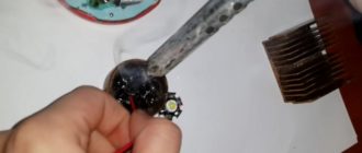
Having first applied a little flux to the LED, I attached the bar to the heater.
LED removed
The LED was soldered within 5-7 seconds, which is very fast, but as you can see in the image, the PCB darkened a little.
Next, I cleared the area of old tin. I used braid for cleaning.
The process of cleaning contacts from solder
After cleaning and wiping the board with alcohol, I decided to try soldering a new LED using soldering paste.
I had solder paste from the mechanical company with a tin content of 63% and a lead content of 37%. I use this paste for rolling balls on chips.
Solder paste
Using a toothpick, I applied just a little solder paste to each contact and installed the LED.
solder paste on the contacts Installed the LED on the solder paste Soldering process
The LED was successfully soldered within 5 seconds. Having washed off the remaining flux, we have a perfectly soldered LED and a not very good darkened strip.
Final version
Eliminating this shortcoming is not a problem; you can simply glue the lens reflector. In 80 percent of cases I glue such reflectors, since with them it will be possible to focus the lens much faster.
LED reflectors LED with lens.
Conclusion
I will definitely use this method of replacing LEDs. I like the fact that you can desolder all the LEDs within a minute. After that, within 5 minutes you can clean the pads, apply solder paste, install new LEDs and quickly solder everything back.
The only significant drawback is the darkening of the PCB, but using reflectors all this can be corrected.
All links to LEDs and the soldering table itself are posted below. Thank you all for watching and good luck with your repairs. I look forward to your feedback on this method.
TABLE-OVEN FOR LED SOLDERING
REFLECTOR LENSES FOR LED BACKLIGHTING
LEDS, GLUE FOR LED BACKLIGHTING TV MATRIX
SOLDERING PASTE
(5 5,00 out of 5)
Source: https://remonter.info/pajka-smd-svetodiodov-s-pomoshhyu-payalnogo-stola/
Soldering LED strip - mistakes and rules. Connectors, when you can’t live without them?
When connecting and installing an LED strip, many people are put off by the need to solder it.
For example, this can be encountered when the tape needs to be shortened, cut, rotated, and then connected to the contact pads. Or simply connect it with wires to a power supply or controller.
People think that only professional radio amateurs and electronics engineers can do this correctly. Therefore, they prefer to buy some connectors or connecting wires for connection.
However, only soldering can make a truly high-quality connection in LED strips.
Disadvantages of connecting connectors
When using a connector, the contact on the tape and the contact on the connector have a fairly small contact area after snapping into place. What does this ultimately reflect?
Due to the reduction in area, heating occurs. Firstly, this affects the LEDs themselves located near the connection point. They begin to degrade and lose brightness faster than the rest of their “brothers” in the backlight.
And secondly, copper without soldering and tinning tends to first darken and then oxidize, forming a greenish coating. That is, oxides are formed that do not conduct electric current. This is typical even for not very small contacts on switches with high currents.
If your contact heats up, the oxidation process will occur much faster and more intensely. Eventually normal contact simply disappears. The LED strip begins to blink spontaneously, go out, etc.
Even if you provide a sufficient contact area, but do not protect the contacts in any way, oxidation processes will still occur sooner or later.
Therefore, soldering is the most reliable and durable way to connect and connect LED strips.
Tools and materials for soldering
This process is not at all complicated; it is enough to have the necessary materials and follow a few basic rules.
Here's everything you'll need:
- soldering iron with a power of no more than 25-40W
- thin copper wires with a cross section of 0.5-0.75mm2
- rosin
- neutral flux gel
- knife or stripper for stripping insulation from wires
- toothpick for convenient application of flux
- tin-lead solder POS-60 or equivalent
Briefly, the entire process should look like this:
1 Prepare the soldering iron
2 Dip in rosin
3 Dip in solder
4 Again in rosin
5 Soldering wires and tape
And now all this in more detail and with certain nuances.
So, you have a tape and contact points on it where you should solder the wires.
First of all, find the marking which contact is “positive” and which is “negative”.
On RGB options there will be one common plus (+12V) and three minuses (RGB). This is important in the future for maintaining polarity and supplying power from the unit.
Strip the ends of the wires from insulation. It is advisable to take multi-colored cores so as not to be confused with the polarity in the future.
Heat up the soldering iron, touch the solder and lower the core into the rosin.
After which, when pulling out the core, immediately bring the soldering iron tip with tin to it.
The tinning process should happen automatically. Do the procedure a couple of times to completely cover the copper core on all sides.
Now you need to tin the contact points on the LED strip. This is best done using flux.
Before doing this, do not forget to thoroughly clean the soldering iron tip.
Dip it in rosin and clean off all excess. This can be done with a special sponge, a simple knife if the carbon deposits are completely ingrained, or use a metal sponge.
The main thing is to prevent any foreign elements from getting onto the contact pad.
Next, take a very small amount of flux on the tip of a toothpick and apply it to the LED strip.
Then touch the solder with a heated soldering iron and apply its tip for 1-2 seconds to the soldering points on the tape.
It is important that the soldering iron is low-power, with a heating temperature of no more than 250 degrees.
What if you don't have a regulator? How to determine the heating temperature?
- look at the sting. It must be clean, not hot.
- when dipping in rosin, the latter should not boil
- there should just be a little smoke coming from the sting
The maximum allowable time for applying the tip to the LED strip is no more than 5 seconds. When using flux, this happens much faster, 1-2 seconds.
As a result, you should end up with two tin tubercles, in which you will then need to “drown” the connecting wires.
Before directly soldering the wires themselves, try on their ends.
They must be stripped exactly along the length of the soldering areas. Usually this is no more than 2mm.
If the bare ends are long enough, then when bent they can easily short out each other. Therefore, always bite off the excess, leaving the tip as short as possible.
Touch the tip of the tubercle on the contact of the LED strip with this tip and apply a soldering iron on top for 1 second. The tin melts and the wire sinks, as if drowning in it. Do the same with the second wire.
As a result, you should end up with a fairly large contact area. But most importantly, this place is covered on all sides with a tin “cushion”, which reliably protects the contacts from oxidation.
For even greater strength, the soldering area can be filled with hot glue and heat shrink applied on top. Then the wires will not fall off even with constant bending.
Soldering silicone coated tape
If the LED strip is completely covered with silicone, there is nothing tricky about soldering it either.
Simply, carefully clean off the silicone from the soldering points with a utility knife, and follow the entire procedure described above.
Silicone here plays the role of additional insulation of LEDs from external conditions.
If you have a tape with IP68 protection, then after all the work with the soldering iron, you will have to reseal the end with the wires.
To do this, you need to try to push the LED strip back into the protective shell and fill the entire space in this place with silicone.
Filling depth is at least 10mm. Then install the plug, also pre-lubricated inside with silicone. The wires are passed through the holes in the plug.
Overlapping connection without wires
To solder two overlapped strips, one of its ends must be tinned on both sides. To do this, carefully remove the double-sided tape from the back side and use a knife to clean the layer of glue.
After this, you place one piece (the one that was treated on both sides) on the other (tinned only on top).
Align the contacts with each other and heat the top strip with a soldering iron so that the solder melts on the bottom too.
True, such a connection is not considered particularly reliable, so it is better to use traditional wires for this purpose.
If you have a long LED strip (up to 5 meters), then it is advisable to solder the power wires to it on both sides. This will ensure that all LEDs glow evenly.
What is the best way to solder wires to an extended LED backlight consisting of several parallel sections?
Typically, for such a connection there is a common power bus (wires with a cross-section of 1.5 mm2), and separate pieces of tape that need to be soldered and connected to this bus.
In this case, it is best to solder the wires to separate pieces at an angle of 90 degrees.
And so as not to put one wire on top of another
The “plus” connection can be made not in the same contact place as the “minus”, but in the next section of the module.
This will not affect the glow of the LEDs in any way.
If you have an RGB LED strip, then you probably noticed that its solder contacts are quite close to each other.
Therefore, when soldering such a backlight, be sure to check that the pads do not short out with a tin track.
If this does happen, and you didn’t notice it, then the minimum that will happen is that the colors will get mixed up, or some of them will disappear.
But if the positive contact and any of the minuses close, this can lead to failure of the power supply or the tape itself.
What to do if the pads are still covered with solder? To fix this, bring the tip of the soldering iron again to the pads, heat the tin and run an ordinary toothpick between the contacts.
The soldering process for RGB is the same as for a simple single-color LED strip. Apply flux (4 drops).
Create tin “pads”.
After that, you recess the wires inside one by one.
To make a branch from 4 or even 5 (RGBW) contacts to the side, and at the same time not interfere with the connection of the second piece of tape, solder only one contact on each module.
Or solder all 4 wires not at the very end, but on the penultimate module.
The tape will still glow properly, no matter where the soldering is.
Thus, having a normal soldering iron, solder and good flux, any beginner can learn how to solder an LED strip.
Of course, installation with connectors is much faster and does not require special tools.
But if you are making LED ceiling lighting for yourself and for many years to come, then losing an extra 10-15 minutes during installation will pay off in the future with a couple of extra years of reliable operation.
However, it is still not worth completely abolishing connecting connectors. If you are assembling some kind of lighting of a complex design, especially high under the ceiling, then you cannot do without them.
Soldering in such places is not only inconvenient, but can also result in accidental damage to the ceiling covering. Yes, and soldering by weight is still a pleasure.
When you move the soldering iron from bottom to top, a drop of solder does not always stick. It is imperative to wear safety glasses when doing this type of work.
Therefore, with complex designs, it is certainly better to opt for connectors.
It will be easier to rearrange the backlight segments and change the configuration.
1Even after one-time soldering and desoldering of wires and tape, it is not advisable to make a connection with a connector in this place.
Due to the difference in the thickness of the tin layers on the plus and minus, somewhere the contact may be better, but somewhere much worse. Therefore, decide in advance which connection you will use.
2Heating the soldering iron to more than 250-300 degrees and soldering with such a tip.
Signs by which this can be determined without having a built-in regulator:
- the soldering iron really starts to smoke
- rosin or flux literally sizzles, boils
- solder does not stick well to the tip
- the surface of the solder at the tip of the tip looks like loose drops with a matte surface, but should shine
- The soldering iron tip becomes covered with black soot
3Use of acid or active flux instead of neutral.
Acid tends to corrode the area around the contact, and the active flux reacts with the metal for a long time after soldering. All this, when manipulating the wires, can lead to damage to the contact even at the time of installation.
4 Unfortunately, cheap Chinese LED strips often use strange alloys instead of copper contacts.
You seem to follow all the rules of soldering: heating up the soldering iron, cleaning it, flux, etc., but the wires still don’t want to be soldered.
Of course, there are no mistakes of yours here, except for one - buying and choosing such a cheap tape.
Source: https://svetosmotr.ru/pajka-svetodiodnoj-lenty/
Soldering LEDs correctly - Build Tool
13.06.2019
When connecting and installing an LED strip, many people are put off by the need to solder it.
For example, this can be encountered when the tape needs to be shortened, cut, rotated, and then connected to the contact pads. Or simply connect it with wires to a power supply or controller.
People think that only professional radio amateurs and electronics engineers can do this correctly. Therefore, they prefer to buy some connectors or connecting wires for connection.
However, only soldering can make a truly high-quality connection in LED strips.