Rules for working with automotive electrical wiring
19.04.2015
To the list of articles
Our country is full of sages who are able to check the wiring “for a spark” and drive for years with the wiring “on twists”. Let’s just keep silent about “bugs” instead of fuses.
Undoubtedly, you can live like this, but today we will talk about the correct and reliable approach to working with automotive electrics. And the emphasis will be placed specifically on wires, connections, connectors, insulation - i.e. interblock elements. I'll tell you about my own experience.
I don’t claim absolute truth, however, I have positive experience, and the knowledge of electronics acquired in due time allows me to make judgments.
All of the following will be true for ordinary urban use of a passenger car. If you plan to work on a vehicle that is used off-road, in conditions of heavy pollution or high humidity (fords, etc.), make appropriate adjustments.
Working conditions
So, first of all, you need to understand that to work with auto electricians you need to have a suitable place, a sufficient set of tools, accuracy, patience and some knowledge of electrical engineering.
You can work successfully with electricians in the field (in fact, I did this many times), but you can also screw everything up in the garage. When you arrive at a service station, you must clearly understand that an electrician and any auto mechanic are different people; the electrician’s post cannot be located in the same place as the mechanic’s. If you see a dirty area, covered in grease, without proper lighting, run away from this shambles quickly. Accordingly, when you work on your own, organize and think through your workplace, and do not do everything “on your knees”. You need to work at a warm temperature: in the cold you will freeze, which means the work will not work well (this is not turning nuts); so the wires will become inflexible, and the electrical tape will become non-sticky - the quality will drop.
The only tool you will need is a 60-watt soldering iron. More precisely, it won’t be needed - it’s too powerful and clumsy. But a soldering iron powered by 12 volts will come in handy, especially if you are going to work not only in a garage where there is 220 V. In any case, a 40-watt soldering iron with a regular tip will be optimal.
I use regular POS-61 solder and FIM flux. Why FIM? Somehow it happened and it turned out to be very effective. But you need to remember that when working with boards (as well as with multi-pin connectors), it needs to be thoroughly washed off, for example, with alcohol - and it’s better not to ignore this, otherwise “glitches” will subsequently begin due to leaks.
You will also need pliers, a small screwdriver, tweezers, alcohol, wire cutters, a knife (scalpel), scissors, a marker, thermal tubes, electrical tape, 0.5mm2 and 0.75mm2 wires (as are the most common).
Separately about the multimeter. Probably, any motorist who is capable of more than adding oil should have it.
An ordinary simple digital multimeter will do - there are plenty of them in any store.
And, of course, the most important thing is your own qualities and knowledge. The more knowledge, the better, and slowly, patiently, with careful checking and testing.
Wiring
Wires should be selected taking into account the current that will pass through them and their length. The most popular are 0.5mm2 and 0.75mm2, you can also use 0.35mm2 for low currents. By type, these are PV-3, PuGV and MGShV - this is what can be easily found in electronics stores.
If it is possible to use “car” PVA wires, that’s also good, but they have no advantages other than a variety of colors.
The laying of new wires should be planned as carefully as possible, otherwise your car after some time will begin to resemble a web that is difficult to disassemble, which also makes it difficult to dismantle parts.
You should try to lay wires in groups, defining common paths. Also, don’t forget about connectors where they may be needed.
There should be no tension on the wires, no load on the blocks or connectors - wires are not cables! Otherwise, they will repay you at the most inopportune moment. We lead the wires freely with a reasonable margin, but so that they do not dangle, so as not to get caught on them later.
It wouldn’t hurt to wrap the wiring harnesses in the cabin with self-adhesive fabric tape for sound insulation. Such a tape can be ordered, at least, in Chinese online stores.
Pay special attention when placing wires in the engine compartment. Here, the danger is posed by high temperatures, rotating and rubbing elements, as well as the possibility of mechanical damage during repairs. Therefore, we plan the location (it can be done along the standard wiring), and we protect the wires themselves in a plastic corrugation.
Soldering connectors
I make connectors (regular car connectors - blade connectors) this way. First, I lightly solder the cable to the connector. After this, I crimp the connector with pliers; it wouldn’t hurt to grab the insulation here, although it’s not necessary. And finally, once again, I solder the connection more carefully. This guarantees both mechanical strength and electrical conductivity.
All that remains is to insulate the connector with a thermal tube.
This technology has proven to be absolutely reliable. It should be said that if you do not re-solder, the connection may break, and this will not be easy to detect, which can lead to “glitches” in operation.
Well, I won’t talk about crimping without soldering: it may be technologically advanced at the factory, but it does not guarantee good conductivity, especially at low currents.
Reliability
You need to understand that during operation, as well as during car repairs, loads and forces involuntarily arise that can damage the electrical wiring.
Therefore, no matter how delicate and high-tech the electronic unit itself is, its housing, external connections, as well as interunit wiring must be mechanically stable and reliable, capable of withstanding not only vibrations, shocks and contamination during operation, but also sloppy and even barbaric treatment during repairs.
The connectors must be securely connected to the wires, because...
Often it is by holding the wires that they try to pull out the connector. Wires can be caught by hands, tools, or other parts. A good option is to use plastic corrugations. In other cases, a thermal tube will help, capable of not only insulating, but also protecting the connection mechanically.
If the detachable connections are not located in an aggressive environment (under the bottom, in front of the bumper, under the wings), they can withstand impacts quite well without additional protection. In other cases, it is worth considering sealed connectors or additional protective treatment and sealing.
Convenience of service
Sooner or later, you yourself or someone else will have to repair either the wiring or any components located next to it. Therefore, try to provide everything so that the wiring can be conveniently dismantled without compromising its integrity - do not skimp on connectors and do not waste time on planning.
Wiring made with wires of the same color is terrible! Any radio store has wires in at least 4-5 colors, and car wires have dozens of colors and their variations. In addition, if necessary, wires of the same color can be marked with a permanent marker: for example, with a longitudinal strip or several transverse ones. This marking may be erased, but not throughout the entire wire, and usually holds up well.
In addition, it would be useful to mark some wires with marks indicating their purpose. It is convenient to make tags from white electrical tape; the inscription is applied with a permanent marker and sticks perfectly.
Diagnostics and testing
We forget about the “control lights” - a multimeter will help us.
After installing the wiring, it would be useful to check what voltage is supplied to the load: whether all connections are reliable, whether there is a high ground resistance. After soldering the multi-pin connectors, we check (without connecting them) the resistance between the contacts, because
Flux could remain on the connector body, creating leaks. These leaks are unnoticeable under heavy loads, but when connecting, for example, LEDs, funny things can begin in the form of “smoldering” and blinking.
You need to understand that the electrical wiring of a modern car includes not only ordinary, but also digital lines (CAN, LIN, OBD, etc.).
If at first we can easily see the voltage or its absence, then when diagnosing digital lines, a multimeter will not help - you cannot do without an oscilloscope.
In general, such lines should be treated with particular caution. Also, in addition to 12V, car wiring also operates at 5V.
Be careful not to apply voltage from the battery to such wires: with a high probability you will “kill” the corresponding unit.
Precautionary measures
Source: http://LADA-2108.ru/tuning.php?id=62
How to make jumper wires with your own hands?
Faced with a completely discharged battery somewhere along the way, the car owner finds himself in a difficult situation.
You have to start the engine “from the pusher” or look for a donor car to light a cigarette by connecting the car’s starter to a third-party power source. An important point: in the trunk you must have special thick cables equipped with clamps.
It is not necessary to purchase them - make reliable wires for lighting your own using the instructions below.
Why not buy cables in a store?
The main reason is this: at the moment the market is saturated with inexpensive products of dubious quality, made, as a rule, in China. Finding truly reliable wires becomes problematic - car stores sell cables that are unsuitable for lighting for the following reasons:
- the cross-section of the copper conductors does not correspond to the declared current carrying capacity;
- the insulation is made too thick in order to imitate a large cross-section conductor;
- the end clamps (the so-called crocodiles) are made of tin coated with a thin layer of copper on top;
- the insulating layer is often made of polyvinyl chloride (PVC), which cracks in the cold;
- fastenings at the points of contact of copper conductors with the crocodile are not reliable.
The result of these problems is large voltage losses, in some cases reaching 1 volt per meter of cable length. This is a serious obstacle to starting a cold engine in a car with a completely dead battery. Insulation cracks can lead to a short circuit to the vehicle body and failure of the donor battery. That is why it is quite difficult for a car enthusiast ignorant of electrics to choose wires for lighting; it is easier to assemble the product yourself.
Requirements for quality conductors
The main task of the cable “cigarette lighter” is to ensure safe transfer of current to the starter of another car with minimal losses for the donor car battery. There are a number of requirements for wires:
- voltage loss - no more than 1 V over the entire length of the cigarette lighter;
- cable type – stranded copper (consists of a large number of thin wires twisted into a single conductor);
- the minimum operating time is 30 seconds, which is exactly what is needed to start a working motor;
- current-carrying conductors must be designed for a current of at least 500 amperes;
- The minimum length of conductors is 2.5 m, the maximum is 4.5 m.
Note. The current value of 500 A is indicated for starters of cars with a power unit displacement of up to 3 liters. For powerful SUVs, small trucks and other commercial vehicles, a wire cross-section is selected that can withstand at least 850 A.
The type of cable insulation plays a big role. On a “cigarette lighter” operated in the middle zone with a minimum winter temperature of minus 40 ° C, the use of an insulating layer of rubber is allowed (for example, a flexible welding cable designed for high currents). For northern regions, a different type of insulation is required, made of frost-resistant silicone that can withstand temperatures of minus 60 °C.
Tips for choosing components
You need to understand that a set of high-quality parts will probably cost more than finished Chinese products. But in a situation where your car’s battery suddenly runs out, or another driver asks for help, the cigarette lighter wires will definitely not fail.
To make your own cigarette lighter wires, you should purchase the following components:
- stranded copper cable, brand KG or KOG, with rubber insulation, working cross-section – 35 mm2;
- stranded wire KOG1 with a cross-section of 16 mm2;
- brass crocodiles for wires, designed for a current of 500 A;
- contact connecting sleeves type GML for cable 35 square – 4 pcs.;
- terminal lugs for M8 screw and cross-section 16 mm2 – 8 pcs.;
- short M8 bolts – 8 pcs.;
- heat shrink insulating tube.
Reference. Cable products such as KG and KOG with rubber insulation are used to connect holders of electric welding machines.
The length of the wires, consisting of a thick welding cable 35 mm2, is selected simply: the “cigarette lighter” should be enough to connect two batteries with a small margin. As a rule, a length of 3 meters is enough.
A thin stranded wire of 16 squares will be used to connect the “crocodiles” with the main current-carrying conductors of large cross-section. Why is the transition to 2 cables of smaller diameter made:
- The 35 mm2 stranded conductor is quite thick. It is quite difficult to screw it directly to the clamp with one screw.
- Insulated crocodile handles cannot be pulled over a powerful cable with a cross-section of 35 squares.
- To ensure reliable electrical contact with the battery terminals, voltage should be applied to both jaws of the clamps. It is for this purpose that the manufacturer provides 2 mounting screws on each side of the crocodile.
To connect the main conductor to the clamps, it is enough to purchase 1 m of welding cable KG with a size of 16 mm2. To avoid buying expensive heat-shrinkable tubing (sold in lengths starting from 1 m), use cheaper cotton insulating tape used in electrical installations. Choose tinned copper sleeves and tips.
Manufacturing procedure
Since homemade wires for lighting will be thicker than cheap Chinese ones, the “crocodiles” will need to be slightly modified. The fact is that the size of standard screws is 4–5 mm, and the tips must be secured with M8 bolts. What should be done:
- Remove the insulating handles from the clamps and remove the factory screws.
- Using an electric drill and a 6.9-7mm drill bit, ream the holes to a larger diameter.
- Using a tap, cut a new M8 thread into the holes.
- Manually screw the contacts to the clamps and make sure that the ends of the bolts protruding inward do not rest against each other and do not interfere with the full spread of the crocodile jaws. Otherwise, trim the screws flush with the surface.
Reference. Some clamp models are equipped with external stiffeners that do not allow screwing large terminals. It is better to check the compatibility of tips with landing pads during the selection of parts.
After finalizing the contacts, proceed to assembly:
- From the thinner cable KOG1, cut pieces up to 25 cm long.
- Clean the ends of the workpieces. On one side, the length of the exposed part should be enough to insert the end of the wire into the terminal, and the edge of the remaining insulation should be flush with the end of the crocodile handle.
- Place the tips on the workpieces and press in the bushings. If there is heat shrink, put it on the exposed part and fix it with a hairdryer.
- Having passed the contacts through the special openings in the jaws, screw them with bolts to both sides of the clamps, tighten the bolts with an open-end wrench. Pull the standard insulating handles.
- Connect pairs of 16 mm2 wires to the main 35 square cable using sleeves. Insulate the connection.
Note. The bare ends of the 16 mm2 cable, adjacent to the brass surface of the “crocodiles” and protected by dielectric handles, may not be insulated.
Ready-made wires for lighting a car can be further improved by installing primitive safety automatics. The task is to protect an electrical circuit carrying a large current from an accidental short circuit. You need to purchase powerful fuses (2 pcs.), designed for a breakdown current of 600 A, and two pairs of connecting lugs. The inserts are mounted in the gap of each wire and, if necessary, can be easily replaced with new ones.
Source: https://autochainik.ru/provoda-dlya-prikurivaniya-svoimi-rukami.html
Selecting wires and cables for wiring in a car
Before installing additional power wiring or when repairing (or replacing) wiring in cars and other vehicles, questions often arise related to the correct selection and use of the wire required for installation. When choosing wires and cables, fire safety requirements come first.
Electrical wiring in any vehicle usually has to be done in the body along the thresholds and corners, through suitable random holes and bulkheads. During operation, wires may well be exposed to low and high temperatures, ice, acids, water, oil, fuel, as well as friction, vibration, shock and shaking and other destructive factors.
We must remember that in the summer the temperature in a car parked in the sun with the windows tightly closed can easily reach plus 5060°C in normal mid-latitudes, and even plus 90°C in southern latitudes. In winter, during severe frosts, a car can cool down in mid-latitude conditions to -30 or 40°C, and in the Urals and the Siberian region to -50 and even 60°C, and in Yakutia even down to minus 70°C.
It is quite dangerous to use rigid wire, which has an unreliable insulation that cracks quite easily and quickly! Such a wire can cause a short circuit in the wiring and a fire! You should use cables and wires that fully correspond to the installation location in terms of current strength, operating and climatic conditions.
Also, the wire must be quite flexible and have strong insulation, which should not harden even when temperatures are below freezing, and in addition, it should not soften when heated. The cable conductor must certainly be multi-wire and copper, so as to conduct the current for which the electrical circuit is designed well and without any losses.
If a current overload occurs in the circuit, or a short circuit occurs, immediately before the special fuse link in the circuit burns out, the conductor should in no case be heated to the maximum temperature from which the melting of the cable insulation begins. If for some reason a fire suddenly occurs, the wire insulation should not spread the fire.
Today, Russian industry produces a fairly wide range of wires and cables that are suitable for power wiring in a wide variety of vehicles.
Foreign industry produces special cables and wires for power wiring in cars. These cables 100% meet the entire range of requirements placed on them. These cables differ from each other by the presence of a certain translucent sheath (that is, insulation) of brown or red color and the rather characteristic weaving of their conductive multi-wire core, consisting of bundles of wire twisted together. Inexpensive cables have wires made of simple copper, and those that are more expensive have wires made of oxygen-free copper, which gives them low resistance and therefore minimal losses. The cables have standard markings, for example: Power Cable - which means power cable Belsis, Proleader, etc. – means the trademark of the supplier or manufacturer OFC – wire made from special oxygen-free copper No. 20 - No. 20 - No. 20 – means the gauge (size) of the conductive cable core of 20 gauge, etc. AWG - American wire gauge SWG - standard grade A BWG - Birmingham wire gauge Wires of the same gauge in different gauges differ slightly from each other in the diameter of their own wire (core). The main gauge for automotive power wiring is the AWG gauge. To select the caliber of the required cable, you should know: • the maximum current consumed by the load; • length of wires from the battery to the load; • the minimum voltage of the battery or other source that is intended to power the load. Each wire must have a similar cross-section (that is, thickness) of the wire conductor, in which the voltage drop across the wire resistance at the maximum (that is, long-term) current consumed will be no more than ten centimeters from the nominal battery voltage. For short-term pulsed current consumption, a voltage drop of 15% is allowed. If the battery has a voltage of +12V, then the maximum permissible voltage drop should not exceed plus 1.2V. Petrol cars, as well as trucks, light diesel cars and buses have an on-board voltage of plus 12V. SUVs, buses and heavy trucks have plus 24V voltage. Reducing the voltage directly across the conductor resistance usually causes the conductor to heat up and release power. Since the cable conductor is placed in an insulating sheath, the insulation itself prevents its subsequent cooling. In order to reduce heating, the conductor cross-section should be selected taking into account the current density coefficient, which for different wiring conditions can have a value from one to ten A/mm2. The average value of current density for an insulated wire, which is laid with open wiring at normal temperature, corresponds to 6 A/mm2. The maximum current consumed by the load according to the rating of the installed fuse link can be determined by the load or the sum of the insert ratings, if there are several similar loads. You can also accurately determine the maximum current when the total ULF output power is known, using the following formula: Imax = P: 6 1 example: you need to calculate the cable size when the battery load plus 12V becomes an audio power amplifier with an output power of 2x200W. The distance between the battery and the amplifier is 6 meters. We carry out the calculation: Load power 2x200W is equal to 400W Maximum current 400W: 6 is equal to 67A Cable cross-section 67A: 6A/mm2 is equal to 11.2 mm2 A cable close to the cross-section is 11.2 mm2, that is, a cable of caliber number 7 AWG, whose cross-section is 10 mm This cable caliber per six meters of conductor resistance has (see table): 6 meters x 0.0018 Ohm equals 0.001 Ohm On the cable conductor, the voltage drop is: 67A per 0.0011 Ohm equals 0.74 V, this is 7.4 percent of the voltage plus 12V From this calculation it follows that the 7-gauge cable is chosen correctly. The cross-section of the current-carrying core is determined by the following formula: S is equal to πD2/4, where π is equal to 3.14, and D is the diameter of the core. In order to prevent a fire from a short circuit on the power wire to ground, a fuse holder (the so-called fuse link) should be installed on the “positive” wire. It is recommended to install “bulb” type fuse holders. They have a distinctive transparent body and allow you to clamp wires up to gauge No. 000. Install it in the cable break in the vicinity of the positive terminal of the battery. The body of the safety holder must be securely fastened. Typically, the rating of a suitable fuse link is selected to be 20 to 30 percent greater than the maximum current consumed by the load. The power wire from the load to the fuse must be the same measured segment (that is, from one piece). If there are connections, this will degrade reliability and may even cause voltage loss as power consumption increases. If for some reason you have to splice wires, to connect them you need to use special “car” couplings, or distributors with reliable clamp-contacts and a well-insulated housing made of heat-resistant plastic. In the absence of special connecting products, so-called terminal blocks, mounting boxes and blocks for industrial or household electrical wiring should be used. It is prohibited to use PVC insulating tape as an insulator for spliced cable ends. If there is a need to install a ferrule on a wire for a contact bolted connection, a ferrule having an internal diameter of the shank that corresponds to the caliber of the wire must be placed on the wire stripped of the top insulation, and the shank must be crimped with a special tool, after which the crimped area must be soldered. When laying the cable, it is recommended, in order to avoid damage, to place it in a corrugated tube of suitable diameter. If the wiring passes through places with rather sharp edges, then the cable should be passed through rubber or nylon seals. The connection between the battery and the load must be made using two differently polarized cables, having insulation of different colors and with the same caliber of current-carrying core. It is forbidden to use a metal chassis or car body as a “negative” power wire, since due to welds, as well as unimportant contact connections, there is a possibility of a drop in the load supply voltage. When assembling a car body, parts of the chassis and body are connected to each other using welding, threaded connections and riveting. These connections are designed to provide the necessary rigidity of the structure and the required galvanic contact between its components, but for power currents they create body transient total resistances. During the operation of a vehicle, mechanical connections are susceptible to corrosion, oxidation and rusting, which leads to an increase in total transient resistances that can reach values from 0.5 to 1.5 Ohms. Vocabulary: Current density is the distribution of electrical energy. current along the conductor section. Electric current is the ordered movement of electrical energy. current in the conductor. Electrical wires - bare or insulated electrical conductors. current, consisting of one or several wires. Electrical cables are a series of insulated conductors (otherwise known as conductors) that are enclosed in a protective sheath.
Power cables are electrical cables for transmitting electricity.
Add comments can only registered users.
[Registration | Entrance ]
Latest answers on the forum ukrelektrik.com
Grounding, grounding
rashpilek1975 Alexzhuk / 37 Electric heating
IusCoin Multiki / 68 Everything about everything - communication
2alpilip Nade4ka / 29
Source: http://ukrelektrik.com/publ/vybor_provoda_i_kabelja_dlja_provedenija_montazha_provodki_v_avtomashine/1-1-0-1097
Wiring in a car: understanding its purpose
Without electrical components, a modern gasoline-powered car cannot even move. But the presence of a diesel power unit will not make the car safe and comfortable to operate. And all because, thanks to wiring, all components and assemblies work as a single mechanism.
In the photo - engine compartment wiring
Features of automotive wiring
Indeed, all these wiring harnesses that encircle the car from top to bottom perform the only task - to ensure the uninterrupted transmission of electrical impulses between the components of a particular system. And if one of the wires has poor contact, or even worse, the terminal is burnt out or oxidized, then the operation of the circuit will be disrupted or even fail.
Replacement is simple; it’s more difficult to find the location of a break or short circuit with your own hands, especially if you don’t know how to do it.
In this article we will try to answer many questions, including:
- how to test the wiring in a car to find a fault;
- how to properly repair the actuator;
- how to restore bad contact;
- how to solve other electrical problems.
Troubleshooting wiring requires basic knowledge and precise tools.
What's under the hood
In the engine compartment there are many wires that perform a wide variety of functions:
- transmitting high voltage pulses from a current source (generator or battery) to the engine cylinders;
- transmitting data from various sensors;
- ensuring continuous operation of the fuel supply system, lighting fixtures, etc.
The wiring of the ignition system deserves the greatest control.
What's in the cabin
Inside the car, intended for the driver and his passengers, there are even more wires, since there are:
- Automotive system controls:
- control of external lighting devices (road lighting, maneuvering signals and rear brake lights);
- management of audio devices;
- automatic transmission control;
- control of electronic assistants (cruise control, automatic windshield wipers, navigation system);
- Control devices and sensors;
- Active safety systems:
- electric seat belts;
- driver and front passenger airbag mechanisms;
- Comfort features:
- air conditioner;
- window regulators;
- musical equipment;
- heating systems for windows, mirrors, seats, etc.
Replacing the wiring in a car will necessarily require disassembling the instrument panel.
Please note! Wiring harnesses go through the interior to the rear of the car.
Therefore, there is a maximum concentration of electrical wiring inside the machine.
How to detect a fault
If one of the electrical devices or actuators stops working, then there is no need to rush to replace it. It cannot be ruled out that the cause of the failure is hidden in a wiring malfunction, and installing new equipment will not solve the problem.
Working with a multimeter makes it easy to determine faulty wires
Any factory manual for a car recommends starting the search for the cause of malfunctions by ringing the electrical wires connecting this device or mechanism to other components.
To do this you need to arm yourself with:
- multimeter;
- or a 12 Volt signal lamp with connecting wires.
How to use a multimeter
Source: https://avtoelektrik-info.ru/zap-chasti/79-provodka-v-mashine
Do-it-yourself auto electrical repairs - instructions for all occasions
Auto electrics are one of the vehicle systems that can be repaired with your own hands. Since many of our compatriots repair their cars themselves, it makes sense to talk about the malfunctions of this system. You can learn more about breakdowns and options for eliminating them from this material.
From time to time, problems with the electrical equipment of a car may occur, and any components in the electrical wiring circuit may fail. If we consider malfunctions of the electrical equipment of a car, then first of all we need to talk about the battery. By its design, the battery consists of cans (6 pieces, each 2 Volts). Over time, the battery loses its capacity and is no longer able to charge.
The battery plates in the car begin to crumble; in general, any breakdowns associated with the battery appear for the following reasons:
- the battery wears out over time;
- the device is subjected to high loads, as a result of which it is regularly discharged;
- the electrolyte level in the banks is insufficient; the problem may also be poor density;
- the presence of mechanical damage to the housing, in particular, cracks through which the electrolyte escapes.
Quite often, wiring problems arise as a result of the failure of the generator unit; this unit is characterized by the following breakdowns:
- lack of charging;
- noise of bearing devices.
Diagnostics of wiring condition using equipment
In the event that there is no charge or it is too weak, the vehicle will run on the battery, and if the latter’s resource is exhausted, it will quickly discharge. Accordingly, the main equipment in the car will not work - the audio system, heater, optics, and perhaps it will not be possible to start the engine. It should also be noted that repairing the car’s electrical equipment can also cause the starter to fail – if this element breaks down, the engine will not be able to start.
Among other malfunctions, the following should be highlighted:
- wiring short;
- lack of contacts in connectors;
- electrical circuit break.
Self-repair of auto electrics - from theory to practice
How to find a short circuit? How to check your car, how to repair wiring and what you need to know about its maintenance? Read more about how car electrical repairs are carried out below.
Checking the integrity of all fuses
The fuse is considered one of the weakest elements in the on-board network. When a short circuit occurs in the system, these parts burn out, thereby protecting all equipment connected to a particular line.
It is best to find a malfunction in the operation of these elements with a multimeter, since visual diagnostics do not always allow you to obtain the desired result.
All work related to diagnostics must be carried out with the ignition turned off (the author of the video is the Auto Electrician HF channel).
The devices are dismantled from their installation locations, after which each mounting socket is diagnosed. It must be taken into account that the short circuit could occur in several circuits at once, so if you find a faulty fuse, this is not a reason to stop the diagnosis. The wiring diagram itself is quite complex, but a professional electrician can tell you about the actual interaction of its circuits. So diagnostics must be carried out for each fuse.
Checking circuit circuits for short circuits
After you have removed the fuses to be tested from the block, you can begin to check the car circuits with your own hands for short circuits. But before this you need to turn off the mass; for the diagnosis itself you will need the same multimeter or lamp. If you are using a light bulb, then one of the wires must be connected to the base, and the second to the central contact.
As for diagnostics, it is performed like this:
- the ignition key must be set to position I;
- The probes should be connected one by one to the terminals of the fuse element holders.
If the light does not light up, then this is normal, but if it does, this indicates a short in the circuit. If you use a multimeter, then everything is simple - you just need to put the tester in current measurement mode (the author of the video is Sergey Martin).
Checking the wiring
In this case, we can only give general advice, since today there are quite a lot of vehicle models, as well as electrical circuit diagrams. If you find a short circuit, you need to figure out why it happened.
To do this, carefully examine the circuit to understand what equipment is connected to it. After this, it will be necessary to turn off each consumer in turn and check its circuit.
If all tested consumers are working normally, most likely the problem lies in the wire.
Accordingly, you will need to change it. If you are unable to remake the harness, then the old conductor will need to be completely removed and a new one installed in its place. But we would still recommend turning to specialists with such a problem, because problems in the operation of the electrical circuit must be solved so that they do not reappear. After all, an electrician who regularly repairs wiring knows better than anyone else what is needed to replace wires.
How to properly connect wires in a car?
There are several options for connecting conductors in a car. The most popular and least reliable of them is twisting wires. To twist, the two ends of the conductors are simply twisted together, and the exposed section of the circuit must be insulated with electrical tape. But still, we would advise using a more reliable connection option, for example, crimping. To do this, you will need a connecting sleeve, which must be selected correctly in diameter, as well as press pliers.
The crimping procedure is carried out as follows:
- First, the insulation is removed from the wiring in accordance with the length of the sleeve.
- After this, the wires must be twisted and placed inside the sleeve.
- Next, everything is crimped using press pliers.
- The resulting connection is isolated.
1. Options for connecting wires 2. Connected soldering wires
Another option - welding - is considered professional, since its implementation will require a welding machine. It is worth noting that this method is also considered reliable. If you don’t have a device, you can resort to soldering; for this you will need a soldering iron with all consumables.
The soldering procedure itself is carried out as follows:
- First, the insulating layer is removed from the conductor.
- Then, using sandpaper, the conductor core is cleaned.
- After this, you need to decide what type of core connection will be used.
- The solder should be brought to the tip of the soldering iron, and then the twist should be heated so that the solder flows into it.
- When the soldering has hardened, the area should be washed with alcohol.
- At the final stage, the connection is isolated.
“How to solder wires correctly”
Detailed recommendations regarding soldering wiring are given in the video below (author - Valera shevchenko channel).
Source: https://avtozam.com/elektronika/avtoelektrika-svoimi-rukami/
Car device
Wires used in cars to transmit electrical energy from sources to consumers during operation experience significant thermal and mechanical loads, and are also susceptible to chemical and corrosive influences.
These include significant temperature changes, vibration and shaking, the negative effects of petroleum products, moisture and pollution. Some wires are designed to carry small amounts of current, which can be affected by various radio interference and electromagnetic fields.
For these reasons, high technological and operational requirements are imposed on electrical wires used for installation of electrical circuits of automobiles.
The electrical system of automobiles can use wires designed to transmit low and high voltage current, while high-voltage wires are usually used in ignition systems of automobile engines with forced ignition of the working mixture.
***
Automotive low voltage wires
Low voltage wires are used for connections in the on-board network. They consist of copper conductors with PVC or rubber insulation. The cores are made of tinned or untinned copper wire, which has high electrical conductivity, elasticity and is technologically simply connected to terminals with plugs and other connecting elements.
For convenience when installing and repairing electrical equipment, alphabetic and numerical designations of terminals and color markings of wires are used. Marking wires by insulation color creates convenience during their installation, maintenance and repair.
Solid coloring of wires uses ten colors; with combined coloring, stripes or rings of white, black, red or blue are additionally applied to the solid coloring.
Thus, the color palette used to mark wires is significantly expanded.
The use of colored wires on a car is governed by certain rules. All connections of products to the car body (“ground”) must be made with wires of the same color (most often black). The wire connecting the switching device (switch, switch) or fuse to the power supply line must have the same color as the wire of the network to which the connection is made.
Sections of the circuit passing through dismountable or non-separable contact connections must be made with wire of the same color.
Sections of the circuit separated by relay contacts, fuses, resistors, etc. must have different colors. The color of wires laid in different bundles to different consumers may be repeated.
Wires may have armored insulation to protect against mechanical damage and braided shielding to reduce the influence of electromagnetic fields (radio interference) on the current flowing through them.
Flexible single-core wires PVA, PGVA (flexible wires with insulation made of polyvinyl chloride plastic, automotive), PVAE (shielded) and PVAL (with tinned core) are recommended for use in bundles operating at temperatures from -40 to +105 ˚C.
For temperatures from -50 to +80 ˚С, PGVA, PGVAD (two-core), PGVAE (shielded) and PGVAB (armored) wires are intended.
PGVA-HL wires are installed on vehicles operated in areas with cold climates (from -60 to 0 ˚С). For portable lamps, SHVPT wires with parallel-laid conductors and PLNT wires with rubber insulation are used.
Braided non-insulated AMG wire is used to connect the negative terminal of the battery to ground and body noise suppression jumpers.
On trucks, KGVVA cable is used in electrical circuits.
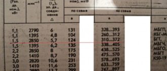
The cross-sectional area of the core in automobile wires can be 0.5; 0.75; 1.0; 1.5; 2.5; 4.0; 6.0; 10.0; 16.0; 25.0; 35.0; 50.0; 70.0; 95 mm2. Insulation thickness – from 0.35 mm (sectional area 0.5 mm2) to 1.6 mm (sectional area 95.0 mm2).
Before installation on the car, the wires are assembled into bundles, which are a complete electrical product containing, in addition to wires, lugs, rubber protective caps, braiding, etc.
The length of the wires in the bundle must be at least 100 mm, the length of the branches must be at least 50 mm.
Promising are flat bundles in which the wires are attached to the base by heat welding. Such harnesses up to 60 mm wide are used on many modern passenger cars (in particular, VAZ-2108, -2109 cars). Flat harnesses are more convenient to maintain and simplify troubleshooting related to breakdowns or breaks in the circuit. In addition, this design of the harness contributes to more efficient cooling of the wires.
Wire ends are made for screw fastening with holes with a diameter of 0.20.5 mm larger than the diameter of the screw or in the form of plugs. Flat plugs are available in thicknesses of 0.20.5 mm and widths of 2.8; 4.8; 6.3 and 9.5 mm. The maximum permissible current for plugs with a width of 2.8 mm is 6 A; 6.3 mm – 2030 A; 9.5 mm – 3040 A.
The cross-section of the wire in the bundle is selected taking into account the thermal load, i.e., ambient temperature, the number of wires in the bundle, the thermal load of the wire and the design of the harness. Thus, at an ambient temperature of 30 ˚C, a harness of a traditional design with 819 wires with a cross-section of 0.5 mm2 allows a current of up to 6.5 A, and a flat harness with wires of a similar cross-section under the same conditions - up to 9.0 A.
For foreign-made wires, when choosing a cross-section, average recommendations are offered, regardless of the number of wires in the bundle. Wires with a core cross-section of less than 1 mm2 are not recommended for installation on vehicles due to their low mechanical strength.
The harnesses in the car are secured with metal or plastic clips. The standards for permissible current loads of wires when laid in bundles decrease with the increase in the number of wires in the bundle.
The wires must be checked for the permissible voltage drop, which is determined from the ratio:
ΔU = ρlI/S,
where ρ is the resistivity of copper wire at a temperature of 20 °C equal to 0.0185 Ohm/m;
l – wire length, m;
I – current strength, A;
S – cross-sectional area of the core, mm2.
If the consumer is connected using a two-wire circuit, then the total wire length l is the total length of the forward and return wires. The voltage drop in a circuit consists not only of the voltage drop in the wire, but also of the voltage drops in the transition contacts of plug connections, switches, connecting panels, etc.
Taking into account voltage drops, the minimum voltage in the high and low beam circuits of the headlights should be 12.6 V, front side lights, turn indicators, rear side lights - 12.3 V, rear turn indicators, brake signal - 12.7 V.
The voltage drop in the starter circuit at a current of 100 A should not exceed 0.2 V for a rated on-board circuit voltage of 12 V and 0.4 V for a rated voltage of 24 V.
***
The development of electronics makes it possible to significantly simplify the vehicle's on-board circuit diagram, reduce the number of harnesses and reduce the weight of electrical wiring and connecting elements.
A multiplex electrical wiring system provides for the connection of two common buses to all devices included in the system: a power bus, through which the “+” supply network is supplied to consumers, and a control bus, through which a signal to turn on or off, encrypted in binary code, passes.
The signal is generated in the multiplexer when the corresponding switch is pressed. The consumer's demultiplexer, having received the signal, decrypts it and, if it matches the switching code of this consumer, connects it to the power supply network.
Consumers are disconnected in the same way. The electronic unit synchronizes the passage of signals.
The control bus can be a light guide in an optical communication system; for this purpose, the control signal is converted from electrical to light.
***
High voltage wires of the ignition system
High-voltage wires, capable of withstanding voltages of up to 15 kV or more, are used in ignition systems of automobile engines with forced ignition of the working mixture. These wires carry high voltage current to the spark plugs from the switchgear to ensure sparking between the spark plug electrodes.
The main requirements for high-voltage wires are low resistivity, resistance to radio interference and good insulating properties. Since these wires operate in conditions of constant vibration and possible contact with petroleum products, they must be elastic and resistant to aggressive environments affecting them.
High-voltage wires are divided into conventional ones - with a metal central conductor, and special ones - with distributed parameters that provide radio interference suppression.
Wires with a copper core (PVV, PVRV, PPOV and VPZS) have insulation made of polyvinyl chloride, rubber or polyethylene, over which a sheath with increased gasoline and oil resistance is put on. These wires have a low central core resistivity (1819)×103 Ohm/m, are designed for a maximum operating voltage of 1525 kV and can only be used in conjunction with noise suppression resistors.
Wires with uniformly distributed resistance are divided into wires with distributed active resistance (resistive wire) and reactance (reactive wire).
The resistive wire has a conductive core made of cotton yarn, impregnated with a soot solution, in a cotton or nylon braid. Such a PVVO wire has a resistivity of (1540) × 103 Ohm/m and is designed for a maximum voltage of 15 kV.
Reactive wires are increasingly used in modern passenger cars (in particular, VAZ brand). The PVVP wire has a central flax thread, on which a layer of ferroplast is applied, which contains manganese, nickel and nickel-zinc powders.
A conductive iron-nickel wire is wound on top of the ferroplastic core. Absorption of radio interference occurs in the conductor and dielectric of the ferroplastic layer.
PVVP wire is available in diameters of 7.2 and 8 mm and is designed for operating voltages of 25 and 40 kV, respectively; has a resistivity of 2 kOhm/m.
The PVVP-8 wire installed on VAZ cars is red.
Wires PVPPV and PVPPV-40 have a similar design and differ only in the materials used in them.
For contactless ignition systems of VAZ cars, a blue PVVP-40 wire with silicone insulation with a resistivity of 2.55 kOhm/m, designed for an operating voltage of up to 40 kV, is used.
Foreign-made wires have higher resistivity values to increase noise suppression ability (for example, Motocraft wires have 11 kOhm/m).
Installing wires with increased resistance can lead to interruptions in the operation of the ignition system. Noise suppression resistors, which are available with a resistance of 513 kOhm, are connected to the spark plug or distributor.
The resistor can be built into a shielded spark plug tip (Fig. 1).
***
Protective equipment for automotive electrical circuits
Olympics and tests
Source: http://kat.ru/mdk.01.01_elektro/61-provoda/index.shtml
How to test wiring in a car with a multimeter
› To the master
articles Best products from AliExpress HERE ⬇
Without electrical components, a modern gasoline-powered car cannot even move. But the presence of a diesel power unit will not make the car safe and comfortable to operate. And all because, thanks to wiring, all components and assemblies work as a single mechanism.
Wiring in a car: from the first motorized strollers to modern cars
It is difficult for a person far from the auto industry to imagine the endless wiring harnesses hidden under the skin of a car. In a modern car, their footage amounts to hundreds of meters, and troubleshooting turns into a whole problem , which can only be solved with the help of special diagnostic equipment. A clear example of the total length of the electrical wiring of a passenger car
Moreover, this pleasure is not cheap; the price of a standard hour at a branded service station will also add considerable costs to the overall estimate of time and financial costs for finding and eliminating faulty electrical wires and electrical circuit components. But in fact, everything is much simpler, since the physical parameters of the wires are also available for checking with your own hands.
And if difficulties arise with the operation of the car, the owner himself can determine the cause of the failure, or find a unit that is operating unstable precisely because of the failure of the connecting wires.
History of development
The appearance of wires in cars is directly associated with three inventions:
- High power rechargeable battery;
- Electric starter;
- Battery ignition.
For reference: The battery and electric starter are a trial-and-error solution for easy engine starting. They simultaneously brought each other under the hood of the car, paving the way for battery ignition and other consumers of electric current.
The modern generation of car enthusiasts, who start the engines of their cars with a half-turn, are unfamiliar and incomprehensible to the problems of age-old motorization. And for the first car owners, the main difficulty was starting the engine. Today's engine starts at the touch of a button
To say that these were temporary difficulties means to hide a century-old layer of history.
In particular:
- Starting the engine took longer than the trip itself;
- All proposed easy starting schemes - springs, flywheels, compressed air, etc. only made the structure heavier;
- A “crooked starter” caused more injuries to drivers than road accidents.
A popular automobile magazine in the 19th century covered all the more or less noteworthy inventions for starting an engine.
Note! The first component in a car that had wires in its design can be considered a magneto, which was installed on the internal combustion engines of the first cars.
Magneto-electric ignition (magneto in the photo below), discovered in 1864 by inventor Marcus, combined:
- Generator;
- Ignition coil;
- Relay interrupter.
Single spark magnetto
Moreover, in 1875, Marcus himself assembled a car with a gasoline engine and electromagnetic ignition. Today, its only surviving copy is considered the oldest car in Europe, having competed for this role with the car of Karl Benz, which was considered the first-born.
In general, the inventors of those years had to solve a lot of questions and problems. For example, Henry Leland, the general director of Cadillac, also needed to replace the wiring in the car with a more functional one.
He invented and introduced into the automotive industry:
- automatic ignition timing regulator;
- The electric starter began to be used commercially in 1911.
Marcus' car already had wires in its design
Further improvements in the ignition and starting systems only added wiring to the design of cars, and this was perceived as a good thing. But later, bundles of wires began to create a problem for the moving parts of the engine and chassis, and automakers began to hide it in the car's design.
Single-wire circuit
Traditionally, all cars were produced using a single-wire circuit, where the role of the second “negative” wire was played by the metal parts of the car body.
- In early cars, wires were used only in the ignition system;
- The high-voltage “+” wire connected the coil to the breaker;
- The second “+” wire from the breaker led to the spark plug;
- The “-” role was played by the cylinder block, also grounded to the frame minus;
- The appearance of two or 4-cylinder units added more wires under the hood;
- The introduction of electric lamps and the electric horn required connection to a power source (generator);
- Introducing side lights forced wires to be pulled into the rear of the car;
- The advent of fuel level sensors added wiring to the gas tank, etc.
In short, the development of modern control and comfort systems led to an increase in wiring in the car. Since cars in those years were built on a frame structure, the wiring harnesses were fixed directly to it.
Note! To protect the car from fire, electrical wiring is laid in special corrugated channels.
Shielded wiring diagram
Two-wire circuit
Despite the simplicity of the single-wire circuit, when the role of the negative wire was performed by the metal body of the car, automakers encountered difficulties from time to time.
In those years, the quality of connections of body parts (riveting, soldering, welding) did not ensure reliable contact, which caused problems with the power supply of various vehicle systems.
Note! Failure of insulation and oxidation of contacts can lead to a short circuit in the wiring at the time of load.
Such consequences are sad, and not uncommon these days - TV news often flashes stories about yet another car burning down. Pay close attention to the wires of your own car!
All this forced automakers to experiment with full-fledged two-wire insulated wiring:
- Cars operated in conditions of high humidity borrowed shielded wiring from power units operating in mines;
- The use of cars for military purposes (armored vehicles) required redundant systems, including double wiring, etc. For example, a proven wiring diagram for UAZ 452 and 469.
In the photo - shielded ignition of UAZ 469
Subsequently, technical difficulties were left behind and a division took place:
- The single-wire circuit is used for the mass automotive industry;
- Two-wire – for special and military vehicles.
Second hands
New cars are a separate category: all automakers, without exception, pay maximum attention to the cars they sell.
Therefore, their share in fire chronicles is negligible, because:
- High level of control on the assembly line;
- Mandatory maintenance for the first 2-3 years;
- Rigid selection of suppliers of components (including wires and electrical components).
And it’s a completely different matter for cars that have been in use - who did what with them, how correctly they followed all the instructions, etc. no one can guarantee . It is quite possible that the car’s wiring was treated this way
But even without the “playful hands” of the previous owner, there are a lot of places in a used car that require control:
- High-voltage wiring of older cars often suffers from problems associated with violation of the integrity of its insulation. If in the evening under the open hood in the area of the wiring you notice bright flashes of electrical discharges, replace all high-voltage wires, including the tips, as quickly as possible.
Note! Simply replacing these wires will improve engine stability.
Don't forget about the center wire. The instructions will tell you the order of execution and warn against erroneous actions.
Strictly follow the car manufacturer's recommendations when servicing wiring.
- Oxidized wiring contacts at the junctions with the body can also create a lot of problems. If you know how to test the wiring in a car, then measure the resistance with an ohmmeter and make sure either that urgent repairs are necessary or that the physical parameters of the contact have been restored.
- Pay attention to twists and solders in the wiring - there should not be any. Most likely, a short circuit occurred in this circuit, and the previous owner replaced only part of the defective wire.
- Inoperative switches should also be carefully inspected. It is likely that the supply wire has fallen off or even rotted due to corrosion.
- Spend time on music equipment installed by previous owners. For ease of installation, electrical wiring could be laid in places not intended for this, which could also pose a fire risk.
Non-standard wiring can be found even under the ceiling trim
Finally
The complexity and saturation of a car with electrical components can be seen in the video in this article. Let us add on our own that it is necessary to constantly devote time to wiring, be it a car or original Java wiring. Sometimes even a quick inspection of the main elements allows you to notice this or that violation, thereby preventing sad consequences for both the car and the owner.
Source: https://sam-avtoelektrik.ru/obshhie-svedeniya/provodka-v-mashine-ot-pervyx-motokolyasok-do-sovremennyx-avto/
How to change wiring in a car even without training to become an auto electrician
There is no place in a car without electrical components; without them, the engine won’t even start. And this applies to both diesel and gasoline engines. Each element performs its specific function, all are connected both to each other and to the on-board computer, which is considered the main control center in the car.
All such nodes are connected into a common network using wiring, and if its integrity is compromised, this can lead to irreparable consequences. Therefore, it is so important for all motorists to monitor the condition of the electrical system.
In this article we will tell you how to change the wiring in a car and check it for breakdowns, as well as much more.
Quality of wiring in the car
All the huge coils of wires connected with clamps that you see under the hood perform a single task - supplying impulses to various components. And if at least one of them breaks or the contact oxidizes, then the operation of the entire system may be disrupted, sometimes the entire computer component completely fails.
It will not be particularly difficult to replace any wire; the most difficult task is that you still need to find it. And this is quite difficult to do, so to help you we will look at the following questions:
- how to check the wiring and find the break point;
- how to repair the actuator;
- how to change wiring in a car;
- how to fix poor contact;
- how to solve other difficulties with electrical equipment.
What's under the hood
Under the hood you can see many wires of different types, quite a lot, and they all perform different functions:
-
The wires transmit high voltage pulses, they come from the battery (or generator) to the engine cylinders.
-
They send data from sensors so that the driver can know how his car is working.
-
The fuel supply system works thanks to high-quality wiring, as well as all lighting fixtures: headlights, brake lights, turn signals.
What's in the cabin
There are many more wires inside the car than under the hood, and all because of the fact that they are located there:
-
Control systems for regulating the operation of: lighting devices: brake lights, headlights, turn signals; sound devices: beep, sound alarm; automatic gearbox; windshield wipers; navigation system;
-
Instruments and sensors that send and display information;
-
Safety devices: electric seat belt drive; mechanisms for proper operation of airbags;
-
Devices to ensure comfort for everyone in the cabin: window lifts; speaker system for playing music; heating systems: seats, windows, mirrors, etc.
How to find a fault
If any of the devices powered by electricity fails, then you don’t need to immediately search the Internet for “how to change the wiring in a car.” Because you don’t need to immediately think that it’s broken. Because there are many cases when drivers immediately throw away this element and buy a new one. And then the car service center finds out that the problem was faulty wiring.
Source: https://vsepoedem.com/story/kak-menyat-provodku-v-avtomobile-dazhe-bez-obucheniya-na-avtoelektrika
Car electrical wiring repair. How to ring and determine the faulty electrical wiring in a car? Diagnostics and repair of car electrical wiring. How to check and repair car electrical wiring
It is difficult for a person far from the auto industry to imagine the endless wiring harnesses that are hidden under the skin of a car.
Their footage in a modern car amounts to hundreds of meters, and troubleshooting becomes a whole problem, which can only be solved with the help of special diagnostic equipment.
And if difficulties arise with the operation of the vehicle, the car owner can determine the cause of the failure with his own hands, or find a unit that is functioning unstable precisely as a result of the failure of the connecting wires.
Wire for car electrical wiring, wire quality requirements
The principle on which the choice of cable should be based is ensuring fire safety, since as a result of quite prosaic reasons, a vehicle is quite easily susceptible to fire. In any wiring, including automotive wiring, there are two main risk factors: current overload and short circuit.
The cable must be selected so as to prevent overheating and current overload when installed correctly, and the wire insulation must protect against possible short circuits, as well as minimize the consequences if this occurs.
And most importantly: it is important that the cable delivers life-giving energy without significant losses. A car cable must be selected taking into account two main aspects: its physical and mechanical parameters and electrical characteristics.
As for the electrical characteristics of the cable, they are responsible for safety and power losses. Two important parameters are the material and diameter of the cable core. They determine certain resistance readings per meter of length. The lower the resistance, the better: less energy is lost on the way from the battery to its destination. In addition, the cable heats up less.
It is much better to use a wire with a copper core rather than an aluminum one. However, the most effective are oxygen-free copper strands. Their resistance is even lower, but such a cable is more expensive. If we talk about the core diameter, then it is advisable to choose a larger one, but do not overdo it.
Physical and mechanical parameters relate more to the insulation than to the core. Insulation plays an important role: it protects the cable from short circuits and exposed cores. Therefore, it is important that the insulation does not melt, tan or crack.
It must have a certain margin of strength so as not to tear under conditions of the slightest friction/tension/rolling.
It should not react in any way with various products of the chemical industry that are intended to “prevent”, “feed” and “treat” the car.
In general, the responsibility of insulation is to withstand all kinds of chemical and physical influences to which the cable is exposed. Additionally, if a fire occurs, the insulation must not spread the fire.
Car wiring diagrams, where can I find the diagram?
Symbols on car electrical diagrams
The electrical circuit of a car is a graphic representation of special pictograms and symbols that have a serial or parallel connection. In this case, the diagram never displays the actual location of these elements, but only indicates their relationship with each other. So, a person who understands them can determine at a glance the principle of operation of an electrical appliance.
In fact, all electrical circuits depict the following groups of elements:
Source: https://prosedan.ru/remont-elektroprovodki-avtomobilya-kak-prozvonit-i-opredelit-neispravnost-elektroprovodki-v-mashine
Why it’s better not to solder wires in a car - what to do
Additional electronic equipment in a car is connected by wires using twists. Even experienced auto electricians try not to solder wiring on electrical appliances, as this is quite dangerous.
Why is soldering dangerous?
There are several negative aspects when soldering electrical wiring can be dangerous:
- soldering on an electrical wire that constantly vibrates when moving may fall off;
- microcracks appear, which often cause short circuits and fires in the car.
Inexperienced repairmen connect twisted wiring with a regular soldering iron and wrap the soldering area with electrical tape. Water gets under the insulation and destroys the soldering. After this, the contact disappears and the connection is broken.
There is also a risk of fire when working with a soldering iron inside a car - one wrong move and the dashboard can melt and catch fire.
What to do if the “Check” light comes on
“Check engine” - this is exactly the translation of the mysterious expression “check engine” for many. Dashboard of many
What kind of soldering of electrical wires can be used in a car?
Experienced auto electricians say that in rare cases it is still possible to solder auto wiring, but this must be done with a special soldering iron and not use electrical tape, but use soldering or heat shrink.
This is a complex method, but it guarantees safety and reliability. Electrical wires connected using heat shrink do not oxidize or break, maintaining good contact at all times.
The principle of this method:
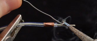
- a solder is put on one end of the electrical wire;
- the veins are twisted together;
- the solder is pulled onto the twist and heated with a hair dryer until solder appears;
- when the solder becomes liquid and plastic, heating must be stopped;
- the tube will tightly grip the connection and prevent moisture from entering it.
How to legally improve headlights in a car
Often, drivers of budget cars do not have enough light on the road. This problem is especially relevant in the autumn, when
It's better to twist
For power cables and headlights, soldering is the best option, but for low-current electrical wires it is necessary to twist them correctly.
The twisted areas must be well insulated and tied to the main harness to prevent unnecessary vibration.
You need to twist the wires in a certain way:
- It is good to clean and level the metal conductors. Strip the braid at a distance of 1.5-2 cm from the junction.
You can use a stationery knife, but you need to do the work carefully without damaging the thin veins.
- After straightening, the veins should look like a broom.
- We connect the 2 metal ends so that the wires are mixed.
- With our hands we tightly twist the wires together along the entire length.
- We tightly insulate and seal.
- We put heat shrink on the connection.
How to repair a burnt-out muffler without welding
The muffler, in addition to the main function of reducing engine noise, also performs several additional tasks - reduces
Every driver should learn how to make correct twists and solder only power cables. The ideal option is crimping, which securely holds the wires together and does not require a soldering iron.
Stay up to date with AUTO news - subscribe to the channel in Yandex.Zen
Source: https://lada-xray2.ru/sovet/pocemu-v-mashine-lucse-ne-paat-provoda