How to use a soldering iron correctly: how to solder boards, contacts and LEDs with wires
Soldering is one of the most effective and simplest ways to connect metal materials, wires and parts. Although soldering work is considered simple, you will need certain knowledge and skills. The most common type of soldering is work done with a soldering iron. To know how to properly solder with a soldering iron with rosin or other types of fluxes, you need to delve a little deeper into the topic.
There are different types of soldering irons that differ in power.
- Electric soldering irons are the most common and operate on electricity.
- Gas - they work using a gas burner.
- Thermal air - use air flow.
- Induction soldering irons - their work is based on heating the tip with a magnetic field.
One of the varieties of this tool is also a soldering iron for rhinestones. It is considered one of the most common elements when working with thermal rhinestones. The technology for using this product is very simple - put the rhinestone on the fabric and apply a soldering iron on top, the glue penetrates the fabric and securely holds them together.
In everyday life, electric soldering irons are most often used, having different powers for different types of work. For soldering electronic components, soldering irons with a power of up to 40 W are used; if the parts have a wall thickness of no more than 1 millimeter, then the device has a power of 80 to 100 W. For thicker-walled parts, soldering irons with a power of over 100 W are used.
Solders and Fluxes
Before you begin soldering work, you need to select solders and fluxes. For electrical soldering, there are different types of solder, which can be soft or hard.
Soft ones include tin-lead alloys, which have a low melting point and are not particularly strong. It is not recommended to use them if the soldering temperature exceeds 100 degrees Celsius. Refractory alloys include silver and copper alloys.
They are perfect for those connections where there will only be a static load on the material, since such alloys are very fragile.
Fluxes are responsible for how the metal will be soldered and how strong the connection will be. Its task is to remove the metal oxide film. The following fluxes are used: various mixtures of rosin and acid. Rosin mixtures are commonly used when soldering electronics, while acid is used to join small wires and small contacts.
Security measures
Organize your workplace; it should be bright and ventilated, as the soldering process produces gases that are harmful to health. It is also recommended to wear glasses to protect your eyes from splashes of molten metal or flux.
Tinning the tip
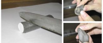
The tip is a cylindrical rod made of copper. Its shape can be changed depending on the type of work. For example, it can be flattened into the shape of a screwdriver tip. This type of sharpening is used when soldering massive parts. You can also grind off a pyramid-shaped tip; it should be used when soldering small parts.
Tinning is used at the preparatory stage and involves covering the tip with a thin layer of solder for better contact with the surface to be connected. This operation will protect the tip from rapid wear and corrosion.
Soldering conductors
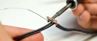
To know how to solder a wire to a contact, you just need to practice a little. Before proceeding directly to soldering, you should thoroughly warm up the soldering tool; when you use it for the first time, the soldering iron begins to smoke - this burns out the lubricant used in its production. It needs to be allowed to cool, then turned on again.
Next, the first thing you need to do is clean the insulation; it can be easily removed with wire cutters in one movement. Insulation in the form of enamel, paint or fabric wrapping must first be burned. Then go over the wires with sandpaper or resort to a chemical method - put the wire on an aspirin tablet and heat it with a soldering iron.
The next step is to apply a little flux to the wire you are going to solder, then use a soldering iron to begin tinning. Immediately after this, you need to connect the two ends of the wire, carefully heat the contact point until the solder melts and quickly remove the soldering iron so as not to overheat the parts.
Modern electronic devices do not have wires. The connection is made by soldering the contact surface. For such types of work, use a low-power soldering iron with a power of 10-12 W. Before use, you can make several copper tips with branches for it. They will allow you to use the tool when working with LEDs and various radio elements.
Working with the board
Before soldering the wire to the board , you need to perform certain actions:
- Insert the part into the previously prepared place.
- Bring the heated soldering iron along with the solder to the soldering area.
- Apply a thin layer of solder to the contacts of the board and the pins of the part.
- Quickly remove the soldering tool.
The heated soldering iron tip should be in contact with the board and contacts at the same time. We remove it only when the soldering area is covered with a thin layer of solder. Excess solder can be removed with copper wire; you just need to bring it to the soldering site.
Induction soldering
This type of soldering is widely used in industry and allows you to connect various conductive metals, such as copper, steel, aluminum, hard alloys, etc. During the operation, non-contact heating occurs due to the formation of eddy currents. To protect parts from oxidation, induction soldering is carried out using fluxes or in a vacuum.
Common mistakes
Typical mistakes made by beginners:
- Don't get lost
- Overheat
- Chemical destruction
- Solder rolling
Failure to solder occurs due to the fact that the soldering iron was not warmed up enough , or the materials being soldered were too refractory, and the soldering iron had too little power.
Overheating is the exact opposite of unsoldering. The main reasons for overheating: using a soldering tool that is too powerful, or leaving it on the soldering area for too long.
Solder rolling occurs due to the fact that the surface of the materials being joined was poorly cleaned. The oxidizing layer on their surface does not allow the solder to spread well, which leads to poor contact of the components being soldered.
Chemical destruction appears at the soldering site due to incorrectly selected flux, and if washing is not carried out after soldering. This leads to corrosion and gradual destruction of the soldering area.
Proper care
A high-quality soldering iron is not a cheap tool, and like any other tool, it requires careful care. Basic rules for caring for it:
- It is not recommended to turn on the soldering iron with the tip removed, as this leads to overheating of the element and significantly reduces the service life of the tool
- Before first use, you need to coat the tip with high-quality flux and tin it.
- After completing the work, you need to thoroughly clean the tip and tin it, this will help to quickly warm up the tool the next time you use it.
- During soldering, you need to periodically apply solder to the tip of the soldering agent, so its tip will last you longer.
Source: https://220v.guru/fizicheskie-ponyatiya-i-pribory/payalniki/kak-pravilno-payat-payalnikom-vidy-payalnyh-rabot.html
How to solder contacts on a board
For professionals, the title of the article may cause a condescending smile. It would seem, what’s so complicated here? I cleaned the contacts, scooped up some solder with the nose of the soldering iron, and applied it to the connection point. For an experienced radio amateur, this process really does not cause problems. But if everyone (including professionals) knows how to solder correctly with a soldering iron, where do unsoldered boards, short circuits between adjacent contacts, and parts that fail due to overheating come from?
Our material will tell novice craftsmen how to learn to solder using traditional and non-standard methods, and for those who consider themselves professionals, it will help improve their skills.
What is soldering
Without referring to Wikipedia, we will explain in our own words. Soldering is the joining of metal contacts using a conductive melt, followed by its solidification. In this case, unlike welding, none of the parts being connected should melt during the process. Of course, after the conductive melt (solder) has solidified, reliable electrical conductivity of the connection must be ensured. Contact resistance cannot affect the characteristics of the electrical circuit.
General rules for working with a soldering iron (we will consider all these points in detail in the review)
- The connection point must be mechanically cleaned of dirt, protective coating and oxides (if the dimensions and design of the parts and conductors allow). What you can focus on: some metals, in principle, cannot be cleaned of the oxide film, at least in air. Only under a continuous layer of special fluxes (we are talking about aluminum and alloys based on it). The fact is that the “winged metal” oxidizes instantly.
- To degrease the connection point, special cleaners are used: fluxes. They should not have a destructive effect on the metal you are working with. Even if the joint seems perfectly clean, soldering without flux is almost impossible. When you touch the heated tip of a soldering iron, thermal oxidation occurs.
Important: metals used in electrical engineering (aluminum, copper, silver, gold) in their pure form have good adhesion.
Standard solders seem to stick to the surface, securely fixing after hardening. The oxide film layer not only prevents “sticking”, it is also a dielectric.
And when heated, fluxes activate their cleaning properties, and not only remove invisible contaminants, but also prevent oxidation.
Special fluxes have been developed for various materials. Even acids are used.
Let us repeat, these are only theoretical principles, from which it is not yet clear how to solder with a soldering iron. You will see detailed instructions below.
Selecting a soldering iron
If you are not involved in radio work professionally (most likely this is the case, otherwise you would not have studied this material), you have in your arsenal an ordinary soldering iron in one copy. We are not talking about a soldering station at all, since it is quite expensive (albeit a very convenient kit). But for a novice master this is overkill.
Let's return to soldering irons. The classic is a nichrome heater and a copper tip. In fact, this is the best combination, but for manual control. No temperature control, smooth slow heating. At the same time, the copper tip holds the temperature perfectly, and often compensates for the heat dissipation at the soldering site. Another advantage is that the soft material allows you to mold any tip configuration. You can literally rivet and cut out a tip for a specific type of soldering.
The only drawback is that copper burns out quickly, and this type of tip is actually a consumable item. It constantly has to be sharpened with a file.
Tip: Be sure to use a hammer before shaping the tip with a file. Once the copper rod is sealed, it will last longer. A little lost time is more than compensated for by ease of use.
The illustration shows the classic “screwdriver” shape. A universal tip for most amateur jobs.
Source: https://vi-pole.ru/kak-propajat-kontakty-na-plate.html
How to solder correctly with a soldering iron, how to desolder a microcircuit
For professionals, the title of the article may cause a condescending smile. It would seem, what’s so complicated here? I cleaned the contacts, scooped up some solder with the nose of the soldering iron, and applied it to the connection point. For an experienced radio amateur, this process really does not cause problems. But if everyone (including professionals) knows how to solder correctly with a soldering iron, where do unsoldered boards, short circuits between adjacent contacts, and parts that fail due to overheating come from?
Our material will tell novice craftsmen how to learn to solder using traditional and non-standard methods, and for those who consider themselves professionals, it will help improve their skills.
How to desolder a microcircuit with a soldering iron
By picking up the microcircuit with a screwdriver and applying slight pressure on it, while simultaneously warming up the legs of the microcircuit located on one side with a soldering iron, you can gradually desolder it. How to do this is shown in more detail in the video at the bottom of the article (watch starting at 15 minutes 15 seconds).
How to solder or desolder a microcircuit without a soldering iron
You already understand that successful soldering requires heating the part to the melting temperature of the solder. It can be melted using a heat gun or soldering hair dryer. This is an analogue of a construction hair dryer, only it is compact and often equipped with special molded nozzles.
With its help, the working area is heated, while the solder melts not at a certain point, but over a relatively large area. This is an effective method, especially if it is necessary to desolder the microcircuit (all legs heat up at the same time). But with this method there is a risk of damaging the part itself from overheating.
If you remove the faulty element, no problem.
In general, a soldering gun should only be used in cases where the traditional soldering method is not possible. For example, when mounting SMD parts (who doesn’t know, they don’t have legs) on a radiator plate.
Flux selection
We will talk about soldering copper parts. There are special acid compositions for iron and aluminum; this is a topic for a separate material.
In fact, it's everyone's personal preference. You just need to try different formulations and determine the best one for yourself. Some people like soldering fat (the consistency is like grease), some like liquid flux. We will talk about traditional rosin.
More precisely, how to solder correctly with it.
This flux is based on pine resins and has excellent cleaning properties. It provides mechanical and chemical cleaning, in addition, it protects the surface well from oxidation when heated. There is only one drawback: in its pure form, rosin is solid. This means that it cannot be applied to the parts to be joined in advance. However, the technology is there:
- Having touched the rosin with the tip of the soldering iron, we collect solder on it;
- we immerse the legs of the part or the wire in the flux using a soldering iron (it melts), while the surface is covered with a thin layer of solder;
- similarly apply solder to the soldering area;
- connect the tinned part (wire) to the soldering point;
- touch the flux with a soldering iron, then pick up solder, dip it in rosin again;
- Immediately transfer the tip to the soldering zone.
Parts have been soldered this way for many decades. With a certain skill, there are no restrictions on the choice of materials for joining. This technique is ideal for training. If you master it, the other methods will seem even easier.
Tip: To clean solder surfaces that have a layer of oxide on them, regular pharmacy aspirin is suitable. It contains acetyl salicylic acid. It must be ground into powder and applied to the contacts.
Soldering with liquid or paste fluxes
The advantage of such compounds is that they can be pre-applied to the connection point. That is, the flux begins to work even before heating. When touched with a soldering iron, the second stage of the reaction occurs, and the liquid flux serves as a lubricant for the spreading of solder.
Another plus is that a paste or liquid cleaner increases the contact patch. The main problem with soldering non-flat objects is that the heat transfer area from the soldering iron is minimal. If the point of contact is moistened with flux, the temperature is transmitted more efficiently.
The only drawback: there is no mechanical impact on the surface.
Information: some old-school professionals dissolve pine rosin with alcohol or a more liquid flux, and an effective composition is obtained with virtually no drawbacks.
What kind of solder to solder
These alloys are made from tin, lead, copper, nickel, or silver. Tin-lead solder (PLS) is used to work with circuit boards and household wiring. Despite the great variety, they can be divided into two types:
- soft (melting point up to 300°C);
- solid (melting point over 300°C).
Any form of release: lump, wire, powder, paste. A universal option is wire up to 2 mm in diameter. It is convenient to put it on the soldering iron tip or insert it directly into the soldering zone.
An interesting offer from manufacturers is solder paste or powder. This is finely dispersed solder, to which liquid flux is added for viscosity. The result is a consistent composition with high adhesion, which can be used for soldering without prior fluxing. We simply apply the paste to the contacts and heat it up.
You can work without a traditional soldering iron, using a soldering iron. Thanks to the fine grinding, the solder melts quickly and instantly spreads over the work area (with the help of flux).
This is a good option for a beginner master. The work is simple, but you won’t be able to learn how to solder efficiently in difficult conditions: when you don’t have good flux and solder at hand.
How to solder with copper
Copper, nickel or silver are used as the base for specialized solders that are not used in consumer electronics. Copper solders have a melting point of 800–900°C, so it is impossible to work with them in relatively delicate printed circuit boards. With their help, contact pads are soldered in electrical engineering; the main application is the assembly of copper pipes. The composition is produced in the form of wire.
Practical advice in unusual situations
- Installation and dismantling of elements with two legs is easy. How to desolder a microcircuit from a board with a soldering iron, since you need to heat several legs at the same time? Use a heat-conducting object with a large area. For example, copper braid.
- If, after removing parts from the board, the hole is closed with solder, use a toothpick.
- A third-hand clamp can be used to secure elements before soldering.
Bottom line
Despite the abundance of theoretical advice, only practice will help you learn how to solder correctly. Take a faulty circuit board from any electronics, remove and solder the components several times. The same applies to splicing wires. A couple of meters of used wiring is enough to get practical experience. Then start the real work.
Source: https://ProFazu.ru/elektrooborudovanie/samodelki-oborud/kak-pravilno-payat.html
How to solder tracks on a board
To restore damaged tracks on the motherboard you will need:
1. Soldering iron with a small tip.
4. Several copper wires 0.1 - 0.3 mm thick.
Repair
1. Use a sharp knife to clean off the protective varnish on the torn tracks:
2. Tin all these tracks using solder and flux (you can also use acid, but after soldering, thoroughly clean the sealed areas with alcohol):
3. Tin the copper wires. It is best to take one long copper wire and tin it, and then cut it to the size necessary to restore the track.
4. You need to start sealing from the outermost damaged track, so that when sealing others, the neighboring ones do not interfere:
5. Having soldered all the wires, clean the soldered areas with alcohol and be sure to test the damaged tracks for breaks.
Hello, friends! Today I will try to tell you almost everything about microcracks in soldering on printed circuit boards. I will not talk here about microcracks in microcircuits, cracks in the compound, in conductive paths, in resistors, capacitors and inductors, transformer cores and quartz resonators. All these are topics for separate articles.
And in this material you can read about what microcracks in soldering look like, why they form, how malfunctions from microcracks manifest themselves, why they are dangerous and how to fix them.
What do microcracks look like in soldering on printed circuit boards?
Microcracks in the soldering around the terminals of radio elements when mounted in a hole are very clearly visible even with the naked eye. Peeling of tracks from the board is also often visible.
Microcracks in the solder around planar radioelements for surface mounting are most often visible under magnification through a microscope at a certain angle of light reflection.
Microcracks in the soldering contacts of BGA microcircuits are not visible even with a microscope. Sometimes they can be seen using a microprobe with a light. The microprobe is a light guide with a lens at the end. It is placed in the gap between the board and the microcircuit.
Watch a video about visual soldering quality control systems:
Why do microcracks form in soldering?
Microcracks around contacts mounted in a hole most often appear at contacts of massive elements (transformers, capacitors, chokes) due to board vibrations, even with high-quality soldering. Cracks often appear around the contacts of power connectors when force is applied to them. For example, frequent malfunctions of flash drives are associated with mechanical stress on the USB connector - over time, the contacts of the connectors peel off or even come off.
Microcracks in the solder on the contacts of SMD components appear from the same vibrations and thermal stresses. Also common causes are defects in soldering - cavities in the thickness of the solder, impurities, cold soldering, sagging, overheating, rapid cooling.
Microcracks in BGA ball contacts appear due to soldering defects - cold soldering, poor wettability of contact surfaces, rapid cooling, displacement during cooling, thermal stress.
Look how boards are soldered in China:
How malfunctions manifest themselves if there are microcracks in the soldering
Microcracks in soldering lead to chattering in contacts, changes in load current, loss or appearance of contact when the device heats up during operation. All this most often damages switching power supplies. They are afraid of sudden voltage drops in high-current circuits.
It happens that the soldering area with a microcrack gets very hot due to the small cross-section of the conductor. In this case, the board begins to turn black and charred, carbon deposits appear, which, as you know, conduct electricity. This is a direct path to failure of the power source and high-voltage circuits.
What are the dangers of microcracks in soldering in working devices?
The most dangerous thing about microcracks is sparking and air breakdown in working electronics. All this is accompanied by flammable sparks, loud bangs, acrid smoke, heating and melting of plastic. This is dangerous for humans.
For an electronic circuit, this is dangerous due to the failure of power transistors, expensive processors and burnout of board tracks. In general, this is not very pleasant and leads to expensive repairs. The photo shows soldering defects in the SMD component (resistor) and inhomogeneities in the BGA balls.
How to fix microcracks in soldering
Fixing microcracks in solder is most often very easy - you need to carry out high-quality soldering with a good flux.
Source: https://ProDemio.ru/kak-pajat-dorozhki-na-plate/
How to solder SMD LEDs correctly
The installation of electronic circuit components is carried out in different ways. One of the most common options is soldering, which ensures reliable contact and strong attachment of parts to the printed circuit board.
It is not very difficult and is accessible even to novice radio amateurs. Soldering SMD LEDs has different features and rules. They are designed to preserve the elements and protect them from overheating. Failure to comply with the requirements leads to the loss of lamps, so it would be useful to consider the issue in more detail.
Basic soldering principles and common mistakes
The process of soldering SMD LEDs consists of applying a thin layer of solder (a low-melting tin-lead alloy with various additives) simultaneously to the contacts of the attached part and the current-carrying tracks of the printed circuit board. Physical processes used:
- wetting of metals with melt;
- capillary impregnation of small gaps between contacts, ensuring connection both mechanically and electrically.
In order to solder SMD diodes, it is necessary to use a special soldering iron with low power and limit the time of contact of the LED device with the hot working part. Experts recommend not to exceed 3-5 seconds. A common mistake is to use soldering irons with a thin tip. This reduces the efficiency of heat transfer and does not allow high-quality heating of the contacts and traces of the printed circuit board.
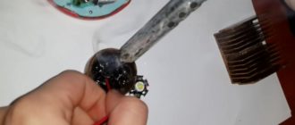
Experienced people recommend using a normal tip, ground at an angle. The large mass will ensure rapid heating of the pads and melting of the solder, eliminating overheating of the LED. Liquid solder, under the influence of wetting and capillary absorption effects, flows into the smallest gaps between the element legs and the printed circuit board track, after which the hot soldering iron is removed to the side. The solder hardens and creates a monolithic area of strong connection of parts.
The second error leading to LED failure is overheating. Excessively long contact of the soldering iron with the legs of the LED element leads to an increase in the temperature of the emitting crystal. If you do not constantly control the duration of contact of the tip with the part, it will not be possible to avoid excessive heating.
Factory soldering
In the factory, other soldering technologies are used that allow several boards to be soldered simultaneously. A special robot installs the necessary elements on the base, on the working side of which solder paste is applied using silk-screen printing.
It contains solder and flux; when heated, they change phase and perform their tasks.
The flux degreases the contacts and provides wetting, and the solder, under the action of capillary effect, flows into the gaps of the connections and ensures a strong connection of the SMD elements.
The process takes place in a special oven, where the board is kept for a certain time. The contact duration and heating mode are selected in such a way as not to harm SMD LEDs. The procedure occurs quite quickly and ensures soldering of elements in industrial quantities.
Important! It will not be possible to repeat this technology at home, since you need to have a full set of equipment and materials. Therefore, it is important for hobbyists to master the process of manual soldering of SMD LEDs using conventional tools and materials.
Required materials and tools
To solder SMD LEDs you will need:
- soldering iron with the necessary parameters;
- side cutters, tweezers, scissors;
- mounting needle or thin awl;
- solder and flux. Regular rosin or a special liquid composition, which is an alcohol solution, will do. An aspirin tablet is often used;
- thin brush for applying liquid flux;
- a magnifying glass on an adjustable stand (bracket), which is used by jewelers;
- soldering gun (component of a soldering station).
It will not be possible to do without flux, since molten solder without it does not wet the contacts and does not settle on the metal. Experts do not recommend an alcohol solution of rosin, as it is ineffective and leaves an indelible white residue.
Choosing a soldering iron is an important preparation step. The best option is a soldering station with a temperature control function. However, a regular low-voltage unit with a supply voltage of 12 to 36 V and a power of 20-30 W is also suitable. It is not recommended to work with a standard 220 V device, as their tip gets too hot. As a result, the flux evaporates faster than it should, not performing its task within the required limits. The maximum heating temperature is 260°.
The type of sting tip is of great importance. A regular cone is not the best option; the optimal choice would be the so-called. microwave. This is a rod cut at approximately 45° with a small recess made in the axial direction. It is filled with liquid solder and allows you to more efficiently apply the material to the SMD LED pads and boards. If necessary, the microwave acts as a suction for excess solder, which avoids drips and drips.
The optimal type of solder is a thin wire with rosin inside. This type allows you to successfully solder LEDs with almost any soldering iron.
How to solder SMD components
Installation of LED elements is technologically significantly different from connecting a lamp. Soldering SMD LEDs requires some experience and skill. If there are none, it is recommended to first practice on some unnecessary pieces of wire.
This will help you master the art of soldering and keep your LEDs in working order. Before starting work, you should inspect the surface of the board.
If it is coated with varnish or a layer of silicone, the current-carrying paths to which the LEDs will be soldered should be freed from them.
The specificity of installing SMD LEDs is the absence of conventional long leads. The elements are installed on the board and soldered to the tracks, for which there are small areas on the sides of the LED device housings. The work requires accuracy and attention.
It is important to remember the danger of heating, reducing the time the soldering iron touches SMD parts as much as possible. If there is no appropriate tool, a copper wire about 1 mm thick is wound around the tip of a conventional soldering iron.
One end of this winding serves as a sting, the heating temperature of which is significantly lower than that of the main element. Let's look at the procedure in more detail:
Work order
The soldering process consists of the following operations:
- removing a burnt out LED (if necessary);
- cleaning conductive paths, applying flux to the soldering area;
- installing a new LED element in place;
- soldering of contacts;
- cleaning the soldering area from flux residues.
It is necessary to constantly remember the contact warm-up time, reducing it as much as possible to acceptable values. The finished soldering should be neat, smooth, without solder sagging or drips. Excess material can be collected with a piece of braided screen, heating the solder and touching it with a bundle of wires.
How to solder with a hair dryer
Soldering with a hair dryer is somewhat reminiscent of the industrial method of mounting SMD LEDs, only instead of an oven with the required temperature, a special hair dryer is used. The process is carried out in stages:
- We apply special thermal paste to the surface of the board. You should not completely cover the base with it; it is enough to apply the material only to the contact pads;
- install the LED using tweezers;
- we direct the flow of hot air and solder the board to the LED element. To protect against overheating, it is recommended to cover it with a metal object.
When hot air is supplied, the pasta melts, forming a layer of flux and liquid solder. The flux evaporates quickly, leaving a strong seal.
https://www.youtube.com/watch?v=LoeEpCUA7J8
A hair dryer is convenient to use for dismantling work. If you need to unsolder many LEDs at once (for example, to replace burnt-out elements on a linear backlight), a hair dryer will quickly heat the board and easily remove even glued parts.
Soldering silicone coated tape
Silicone protection is applied to prevent contact of the tape with moisture. For soldering, it is necessary to remove the coating layer. To do this, cut the tape with a sharp knife and carefully remove the protection.
After this, the current-carrying paths are thoroughly cleaned and degreased, flux is applied and the LEDs are soldered. At the end of the work, it is necessary to re-apply a layer of transparent silicone to the cleaned area.
You can use a regular plumbing compound, which hardens for about a day (depending on the thickness of the layer).
Main conclusions
Soldering SMD LEDs is not very difficult, but requires care and caution. You should remember the danger of overheating of the elements, which will result in their failure. It is necessary to ensure compliance with the following conditions:
- use a low-power soldering iron with a heating temperature no higher than 260°;
- use high-quality flux (experts recommend a special composition for soldering aluminum);
- limit the contact time of LEDs with the soldering iron.
In addition, you must remember to maintain polarity and monitor the condition of the current-carrying paths. Please share your options for soldering SMD LEDs in the comments.
PreviousNext
Source: https://svetilnik.info/svetodiody/pajka-svetodiodov-smd.html
How to restore a cable: expert advice
Cables are a type of wire that is used to connect various printed circuit boards and electronic elements inside a device. They have many varieties and soldering features. Depending on the internal cross-section of the installed contacts, the conductivity will be higher or lower. This also applies to the type of soldering material.
If the question arises of how to restore a cable if it is damaged yourself, then many different nuances should be taken into account. The article will describe the main elements and provide information on how to solder contacts on various devices.
Peculiarities
Before you start considering the question of how to restore a torn cable, you should study its features. Depending on the type of device or printed circuit board, this type of wire can be either flat or circular. In addition, various elements in the form of technical varnish, graphite coating or rubberized braiding can be applied over the contacts and the conductor itself.
If the cable on the moving modules of the device is damaged, for example, on the print head of the printer, then it is necessary to clean the contacts from the rubberized braid. Loops on screens and phones can be applied on top of a printed silicon board. They have a flat appearance and are protected by graphite coating.
Purpose
The main purpose of each loop is to transmit a short or long electrical pulse between the device modules. Depending on the type and thickness, as well as the material of the conductor, the signal is transmitted at a certain speed.
This is important to consider, since if it is necessary to replace the conductive element itself, a copper wire of the required alloy will be required. Otherwise, contact may not proceed. The cables are convenient to place in compact equipment models due to their small size. Often this type of connection is used in mobile phones, laptops or screens.
Conductors can vary in the number of wires and contacts inside. Stubs with a single conductor element are usually installed on top of silicon circuit boards.
If you need to connect a screen or hard drive, then a multi-threaded connection type will be used. It can have up to 40 grip points. It is these cables that are most often subject to damage, since soldering occurs on all contacts.
If at least one of them is damaged, the device will cease to function normally.
Malfunctions related to damage
Determining that equipment is damaged due to a loop is quite simple. If you look at the screen of a laptop or TV, then due to damage to the conductor, the matrix will begin to flicker or the image will partially disappear. This is due to the fact that such a connection channel to the main board is responsible for projecting the signal. The damaged area will be broadcast with interruptions in the image precisely at the point where the contacts are soldered.
In any case, you can make sure that the problem is in the cable only by disassembling the device itself and checking the voltage at each of its contacts. Usually such interruptions are visible to the naked eye.
The main visual signs of damage include the following:
- Darkening in the places where the cable conductor goes.
- Kinks and tears in the tape.
- Damaged contacts at solder points.
In any case, such problems cannot be corrected with ordinary glue. Here you will need rosin, tin, alcohol and a soldering station.
Which devices often need repairs?
Every time the owner of household appliances and electronics is faced with the question of how to restore a cable, he must understand that the operation of soldering or stripping contacts itself carries a certain risk. If you fix a problem on the cable without the necessary tools or materials, there is a risk of damaging neighboring modules.
The owners of the workshops become frequent clients:
- TVs, monitors, laptop screens.
- Keyboards.
- Laptops and PCs.
- Phones.
The problem is not the quality of the conductors themselves, but the risk of damage to them. If we consider a mobile phone, the cable is mainly damaged due to contact with liquid. As a result, the contacts burn out at the soldering points.
Keyboard wires wear out from frequent use of keys and switches. This leads to the fact that the conductor itself wears off over time and conductivity decreases. If we consider laptops and personal computers, the problem may arise due to a power surge or incorrect connection of the conductor itself.
Screens
The question of how to restore the display cable is quite complex. It all depends on the brand and model of the matrix and the boards to which such a screen is attached. It could be a laptop, monitor, tablet, all-in-one or TV. Each of the listed devices uses its own soldering method and technology for applying binding materials.
Damaged contacts at the coupling points must be completely cleaned. You can use a blade or scalpel for this. Then you will need to strip the wires to fix them in place where they are soldered to the board.
It is better to use a soldering iron with a small tip to prevent tin from getting on other elements. If you need to build up a damaged area if it is broken or bent, then you will need a similar wire model.
You can find it on the radio market or on the Internet, on thematic resources.
When considering the question of how to restore a cable on a matrix, it is necessary to test each connected element or contact before starting the repair. This is done using a voltmeter. It shows the voltage at each section. This must be done in order to not only find the source of the damage, but also its cause, which may be a damaged part.
Keyboards
Fans of computer games and constant correspondence become frequent clients of workshops asking how to restore a cable on a keyboard. It is a common practice for a keyboard to become unusable after several years of active use.
A frayed cable will have to be replaced. For these purposes, you will need copper wire of a suitable cross-section. The contact itself is flat and located over the entire area of the printed circuit board, which is responsible for transmitting information after pressing a specific button on the keyboard. You will need to clean the varnish layer and remove the frayed wire. After this, a new one is placed in its place and fixed with conductive glue. Then technical varnish is applied.
It is not difficult to restore the keyboard cable. If performed correctly, the operation will take no more than 30-40 minutes. The main thing is that all contacts are well treated with varnish and glue.
Laptops
There are several ways to restore a laptop cable. The contacts and wires located on the motherboard are of a replaceable type. If damage is detected on them, it is better to replace the wire itself. It costs much less than the materials that would be required to restore it.
If the components cannot be found, you can replace it. To do this, you will need to select a suitable wire cross-section. This method is not suitable for multi-core loops.
The damaged conductor is removed from the contact point on the board. After this, the braided wire is carefully threaded into the forks at the clutch points. They use latches so you can secure them with a flathead screwdriver.
If it is necessary to restore a multi-core cable, then the damaged area should be cleaned and the break should be extended using conductor compound. Conductive glue is often used for these purposes.
Phones
Another popular question is how to restore a cable on a phone after it gets into water. Upon contact with it, the screen of the mobile device begins to darken. This is a sign that the cable contacts on the matrix are damaged.
In order to fix this, you will need to replace the conductor. It must be carefully cut away from the place where it is fixed on the main board and disconnected from the phone screen. After purchasing a new wire, it should first be soldered to the main board exactly in the place where the old wire was. Next, the contacts are attached to the smartphone matrix.
What you need to know about recovery
If we talk about how to restore a track on a cable, then first of all you should understand the procedure for repairing such a conductor. A special feature of the tracks is that they are not contained in a protected casing or rubber braid, but on the printed circuit board itself.
The main difficulty is that the contacts are flat, and in order to remove them you will need to clean off the base layer of protective varnish. To correct the damage, they can be replaced with wires and round copper fishing line. The conductor is fixed using conductive glue. After this, varnish is applied on top.
When connecting a stranded conductor, it is important that each individual contact is well soldered. You can verify the conductivity of all flows using a voltmeter.
What materials and tools will be required
When considering the question of how to restore a track on a cable, you need to know what materials and tools will be needed to perform this action.
In most cases, when repairing or replacing a conductor, a soldering iron or soldering station will be needed. When using a nozzle, it is important to install the needle as a heater, since it is this that will allow you to accurately apply the tin to adhere all the elements.
Technical varnish and conductive glue will also be needed when repairing the cable. Depending on its type and shape, you will have to purchase consumables in the form of wires of the required size and cross-section. In order to increase the accuracy of the adhesion of each element, it is recommended to use a magnifying glass or microscope.
How the repair is carried out
There are several ways to restore the loop contacts. The main and simplest of them is the use of conductive glue. It can be found in specialized equipment repair stores.
All types of work differ depending on the device model and the nature of the damage. The general procedure for performing recovery is as follows:
- Clean the cable where it is damaged.
- Remove the damaged area.
- Apply glue or install a new conductor.
- Secure the wire at the junction.
- Using a soldering station, apply tin for joining.
- Apply a protective layer of varnish over the conductor or wrap the conductor with electrical tape.
Do not start the device right away, as the protective layer of varnish or tin may not fully harden. It is important to be careful when applying all liquid solutions to the board to avoid touching other conductive components.
Precautionary measures
When considering the question of whether the cable can be restored, it is important to know what problems may arise during this action. It is not recommended to solder the conductor in modern smartphones. Unlike older phone models, special equipment will be required to repair matrices. It will be impossible to do this at home using a blowtorch.
When replacing a conductor, only install an identical one. If you replace it with a high- or low-conductivity one, as a result of a voltage surge, the connected element may completely fail. After replacement, all stripped elements must be covered with a protective layer. They should not be left open, as this may lead to overheating of the conductor itself.
What to do if the cable installation failed
Having figured out how to restore the cable, you can get to work. To achieve a successful result, you must carefully follow each step and apply the solder adhesive carefully. Only after the applied mass has hardened can the device be tested. To do this, check the voltage level on the connected element with a voltmeter.
If there is no voltage and the cable itself does not function, it is better to seek help from a specialized workshop. Not all parts and cables can be glued or soldered at home.
However, experienced specialists note that a set of tools and materials will not be enough to carry out soldering. To do this, expensive equipment and various devices are used, which would be problematic to purchase on your own. Therefore, to avoid the risk of damage, it is better to immediately seek help from professionals.
Source: https://FB.ru/article/436167/kak-vosstanovit-shleyf-sovetyi-spetsialistov
All about microcracks in soldering on printed circuit boards
Hello, friends! Today I will try to tell you almost everything about microcracks in soldering on printed circuit boards. I will not talk here about microcracks in microcircuits, cracks in the compound, in conductive paths, in resistors, capacitors and inductors, transformer cores and quartz resonators. All these are topics for separate articles.
And in this material you can read about what microcracks in soldering look like, why they form, how malfunctions from microcracks manifest themselves, why they are dangerous and how to fix them.
Notes from a master. If the “nickel” was torn off with the “legs” - android.mobile-review.com
Hello!
Let's figure out what kind of legs these are, what kind of nickels they are and what to do with them. Nickels are often called contact pads on the board onto which the legs of the elements are soldered. The “nickels” themselves are most often just a plate of copper or brass foil, which ends the conductive path on the board.
Legs are the legs of the elements with which the element is soldered to the nickels.
If used carelessly, implying strong mechanical impact, the element can come off the board, tearing out that same contact pad and making restoration either more problematic or impractical.
The complexity of the repair also depends on how exactly the tracks are laid on the board.
For such work I use binoculars. But if you don’t have a binocular, you can easily get by with a magnifying glass, since the elements are not so small.
Today we have a simple Chinese tablet being repaired, which they very persistently wanted to charge and, without calculating the strength, they tore out the charging connector, as they say, “with meat”.
What is surprising is not the fact of damage itself, but the fact that with such barbaric treatment only two contact pads were damaged. Lucky.
The owner of the tablet said that he contacted a couple of workshops and either they told him that they couldn’t do it, or they quoted an amount of half the cost of the tablet. As a result, he gave the tablet to me for experiments for a symbolic 500 rubles. If everything goes well, this tablet will become an excellent car navigator.
Well, let's revive it.
A few words instead of a conclusion
Many people prefer not to bother with such repairs, since in this case the cost of the time spent turns out to be too high in relation to the cost of the device. But if you do this for yourself, then why not. The main thing is to use high-quality soldering irons, do not neglect protection and always have a spare tool on hand. Unbreakable equipment to everyone!
Source: http://android.mobile-review.com/articles/51855/
How to solder SMD chips
Every novice electronics engineer asked the question: “How to solder microcircuits, since the distance between their terminals is very small?” You can read about different types of microcircuit packages in this article. Well, in this article I will show how I solder SMD chips, the pins of which are located around the perimeter of the chip. Each electronics engineer has his own secret for soldering such microcircuits. In this article I will show my method.
Removing the old microcircuit
Each microcircuit has a so-called “key”. I have highlighted it in a red circle.
This is the mark from which pin numbering begins. In microcircuits, pins are counted counterclockwise. Sometimes the printed circuit board itself indicates how the chip should be soldered, and also shows the pin numbers.
In the photo we see that the edge of the white square on the printed circuit board itself is cut off, which means that the chip should be positioned in this direction with the key. But more often than not they don’t show it.
Therefore, before unsoldering the microcircuit, be sure to remember how it stood or take a photo of it, since your mobile phone is always at hand.
To begin, generously lubricate all tracks with Flux Plus gel flux.
Ready!
We set the temperature of the hair dryer to 330-350 degrees and begin to “fry” our microcircuit with calm circular movements around the perimeter.
I want to brag about one thing. For me it came complete with a soldering station. I call it a chip extractor.
Currently, the Chinese have improved this tool, and now it looks something like this:
This is what the attachments look like for it
You can buy it using this link.
As soon as we see that the solder begins to melt, we take hold of the edge of the microcircuit and begin to lift it.
The chip extractor antennae have a very large springing effect. If we lift the microcircuit with some piece of iron, for example, tweezers, then we have every chance of tearing out the contact tracks (spots) along with the microcircuit. Thanks to the springy antennae, the microcircuit is unsoldered from the board only at the moment when the solder is completely melted.
This moment has come.
Installation of a new microcircuit
Using a soldering iron and copper braid, we clean the spots from excess solder. In my opinion, the best copper braid is Goot Wick.
Here's what we got:
Next, take a soldering iron with solder and begin to tin all the spots so that the solder settles on them.
It should look like this
The main thing here is not to skimp on flux and solder. The result is a kind of mounds on which we will plant our new microcircuit.
Now we need to clean this whole thing from all sorts of soot and debris. To do this, use a cotton swab dipped in Flux-Off or alcohol. Read more about chemistry here. We must have clean and beautiful contact tracks prepared for the microcircuit.
Finally, we lubricate the whole thing a little with flux.
We put the new microcircuit on the key and begin to fry it, while holding the hair dryer as vertically as possible and moving it around the perimeter in a circular motion.
Finally, we lubricate it a little with flux and “smooth” the contacts of the microcircuit along the perimeter to the nickels using a soldering iron.
I think this is the easiest way to seal SMD chips. If the microcircuit is new, then it will be necessary to tin its contacts with LTI-120 flux and solder. Flux LTI-120 is considered a neutral flux, therefore, it will not harm the microcircuit.
I think now you know how to solder microcircuits correctly.
Source: https://www.RusElectronic.com/kak-pajat-mikroskhjemy/
How to desolder a microcircuit
The need to dismantle radio elements arises in several cases:
- Dismantling the faulty element;
- Incorrect installation of the radio component;
- Soldering from the donor board due to the lack of a new microcircuit.
In all these cases, except for the first, the main conditions are maintaining the integrity and working condition of the soldered part and the integrity of the printed circuit board.
Dismantled microcircuits
To carry out this work, it is necessary to observe accuracy and simple rules that were developed back when most of the range of radio components was in short supply. The urgent question was how to remove an expensive microcircuit from the board without damaging it.
Chip types
The wide variety of microcircuit packages has led to the fact that soldering techniques began to differ. Previously, the most widespread were microcircuits with pin pins for mounting into holes on a printed circuit board. Subsequently, with an increase in the degree of integration and the widespread use of automated soldering lines, surface mount elements with flat or ball leads began to be used.
ICs (integrated circuits) with solder pins are typically DIP and SIP packages with two and one row of pins, respectively.
Surface mounting ( SMD ) allows installation of ICs with pins of the following types:
- Flat leads brought outside the housing - SOIC, SOP, QFP (square housing);
- Flat legs, bent inward, under the body - SOJ, PLCC, QFJ;
- Ball terminals - BGA.
Each variety has several subspecies. The total number of housing types is in the dozens.
Safe work with semiconductor radio components
Before you unsolder a part from the board with a soldering iron, you need to know the following. Semiconductor elements are extremely sensitive to overheating. Also, tracks on a printed circuit board at high temperatures or when the soldering time is exceeded can peel off from the substrate or break, which is even worse.
Temperature conditions
Soldering station - operating principle and types
The temperature of the soldering iron tip should be 200-250⁰С. At higher temperatures, peeling of the printed tracks and overheating of the microcircuit may occur. The same goals are set for the soldering time of one leg - no more than 3 seconds.
Note! Some sites advise for dismantling to focus not on the temperature, but on the power of the soldering iron. It is not right. Their temperatures are the same, it’s just that a less powerful one may not be able to cope with melting the solder at the pin due to intense heat removal, and a too powerful one can easily overheat the pins and the board. The best option is a 40 W soldering iron.
Many microcircuits are sensitive to static electricity. It is necessary to work with an electrostatic wrist strap on and a grounded tool.
Electrostatic bracelet
Board design
DIY soldering station
Printed circuit boards differ in the number of printed layers and the method of installing radio components:
- Single layer;
- Double layer;
- Multilayer;
- For DIP elements;
- For SMD components.
One board can contain both DIP and SMD elements on one or both sides. Multilayer printed circuit boards, in addition to outer layers, have internal ones, which usually serve for general shielding or wiring of power circuits. Thus, the motherboards of modern computers or mobile phones have up to seven layers.
Multilayer PCB
Dismantling techniques
The method of soldering microcircuits depends mainly on the type of pins, although there are universal methods.
Dismantling the microcircuit with a soldering iron
How to test a zener diode with a multimeter
This is the most time-consuming and unreliable method. It is used only when the number of microcircuit legs is minimal. Before soldering microcircuits with a soldering iron, the tip of the tip is carefully tinned and cleaned of solder residues so that it remains only in the form of a thin film. The molten solder that surrounds the IC leg is transferred to the tip under the action of tension. By repeating the procedure several times, the leads are completely released.
Important! Before each touch of the board, the tip is cleared of solder. The touch time should not be more than three seconds. If the leg is not completely freed, you can only work on it after some time has cooled down. At this time, you can make the following conclusions.
Removing the chip using a razor blade
When working with planar elements, an ordinary razor blade will come to the rescue. For convenience, the razor blade is broken in half lengthwise. Leaning the blade close to the border of the terminal and the board, heat the scion until it melts. By inserting a blade between the leg and the board, they are separated. The blade is made of stainless steel, so solder does not stick to it.
Using dismantling braid
The special dismantling braid works thanks to the capillary effect, drawing in the molten material. You can use braided shielded cable with the same effect. The braid must be clean, without traces of oxidation. In order to improve the spreading of the melt, the braid is moistened with liquid flux.
Dismantling microcircuits using a desoldering pump
The desalination pump is a special piston that, when moving, draws in the melt, releasing the outlet. This method is suitable for working with DIP and SIP components.
Desoldering pump
Using medical needles
This method has proven to work best when dismantling ICs, especially for single-sided printed material. Double sided PCB can also be used to remove needles from syringes. When choosing a needle, you need to ensure that its inner diameter allows the leg of the microcircuit to fit freely, and its outer diameter allows it to fit into the hole on the printed circuit board. The tip of the needle is ground with a file until a smooth surface is obtained.
The needle is placed on the tip of the leg and the terminal is heated with a soldering iron. After the solder has melted, the needle is inserted into the hole of the board and smoothly rotated around the axis until the tin solidifies. After this, the needle is removed from the stem, which is now completely free. The needle material (stainless steel) is not tinned, so rotation around the stem is only necessary to make it easier to remove it from the hole.
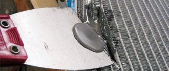
Use of alloy rose
Using a rose alloy, you can desolder all the terminals of the IC at the same time, due to the fact that the low-melting alloy spreads between the terminals and evenly and simultaneously transfers heat to all of them from the heated soldering iron tip. After complete heating, the part is carefully removed from the board using tweezers.
This method has one disadvantage - after dismantling, it will not be possible to collect the remaining rose alloy, since it will be clogged with excess tin and lead, which will change its composition and melting point.
How to desolder a microcircuit from a board with a hairdryer
When working with SOJ, PLCC, QFJ and BGA packages, a soldering station or hair dryer with temperature control is required. Using the station, the entire section of the board is heated until the microcircuit is released, and using a hair dryer with a nozzle, a stream of hot air is directed to the terminals of the IC until they are released.
Radioelements must be desoldered at a temperature of 250⁰C. To prevent overheating, adjacent elements should be covered with aluminum foil.
How to remove capacitors from a motherboard
To desolder capacitors or other two-terminal elements, there is no need to use a special soldering tool. During the dismantling process, one of the terminals of the capacitor is heated, while simultaneously tilting the element so that the leg comes out of the hole. Next, repeat the same with the second leg, tilting the part in the opposite direction. To avoid tearing, do not press hard on the capacitor. By warming up both terminals in turn, they are gradually released.
Source: https://amperof.ru/sovety-elektrika/kak-vypayat-mikrosxemu.html