How to choose the right soldering iron and learn how to solder wires
Soldering is the primary method of electrical and mechanical joining of both parts and wiring. But despite the apparent simplicity of the process, soldering is quite complex and painstaking. That is why, before picking up a soldering iron, you need to have a good idea of what, why and, most importantly, how to solder wires.
Tools and accessories
Soldering, like any other technical process, involves the use of certain tools and accessories. You will need a few tools: a soldering iron, a knife, pliers, a file, sandpaper.
There are even fewer accessories - soldering flux and alcohol or gasoline are enough. Nevertheless, all of these are important components of the process and the choice of both must be taken extremely seriously.
Both the mechanical and electrical reliability of the soldered joint will depend on the quality of the soldering iron and the availability of the necessary accessories.
Selecting and preparing a soldering iron
This is perhaps the most crucial stage. A poorly chosen or improperly prepared tool will not produce high-quality soldering.
Power and type
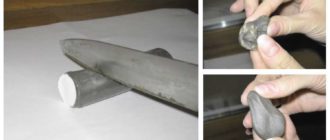
The main criterion for choosing a soldering iron is its power. The industry produces instruments with power from 10 to 200 W and higher. The former can be the size of a fountain pen, the latter look like a natural hammer of impressive size.
Electric soldering irons with a power of 30 (left), 60 and 200 W.
All that remains is to decide which soldering iron to choose for soldering wires. Here everything will depend on the operation being performed, or more precisely, on the thickness and massiveness of the parts that need to be soldered. The more massive the parts, the greater the heat capacity the tool should have. An approximate dependence of the recommended soldering iron power on the task being performed can be presented in the following table:
- 15-25 W – small radio elements, microcircuits, conductors with a diameter of up to 0.3-0.5 mm;
- 30-40 W – large radio elements, wires with a diameter of up to 1 mm, including multi-core ones;
- 40-60 W – fairly large parts, conductors with a diameter of up to 2 mm;
- 100 W – massive parts, wires with a diameter of up to 3-4 mm;
- more than 100 W – power wiring with a diameter of more than 4 mm.
If you don’t have a soldering iron with the necessary characteristics at hand, you can take a slightly larger one in power, but not vice versa. With a massive device, it is possible to solder thin wires with a certain skill, but with a small and low-power thick one, it is almost never possible. Ideally, your household will have several electric soldering irons of varying power.
But what to do if there is no soldering iron of the required power or if it does not exist in nature at all? Trying to solder busbars into a pencil thick with a 100-watt soldering iron? In no case! In this situation, regular fire will help.
Place the parts prepared for soldering, for example, in the flame of a household gas burner or alcohol lamp and solder. Additional heating will help to perform high-quality soldering even with low-power tools.
The only thing is, when heating the wires over an open flame, do not overdo it - a little additional heating is enough.
Separately, it is worth noting the so-called “pistol” or pulse soldering irons, which were widely used, and even today are in service with craftsmen on the road.
A modern version of a pistol soldering iron.
At first glance, the advantages of such a device are obvious - it heats up instantly and cools down just as quickly. But this feature is convenient only for a narrow circle of specialists - on-call specialists. He came, took it out of the suitcase, poked it, put it in the suitcase, took the money and left. But anyone who has seriously worked with such soldering irons knows very well their shortcomings.
Source: https://pochini.guru/sovety-mastera/kak-payat-provoda
Soldering resistors to the board
What are the advantages of using such chip elements? Let's figure it out.
The advantages of this type of installation
Firstly, the use of chip components significantly reduces the size of finished printed circuit boards and their weight, as a result of which this device will require a small compact case. This way you can assemble very compact and miniature devices.
The use of chip elements makes it possible to save a printed circuit board (fiberglass), as well as ferric chloride for etching them, in addition, you do not have to waste time on drilling holes, in any case, this does not take much time and money.
Boards made in this way are easier to repair and easier to replace radio elements on the board.
You can make double-sided boards and place elements on both sides of the board. Well, it saves money, because chip components are cheap, and buying them in bulk is very profitable.
First, let's define the term surface mounting, what does it mean? Surface mounting is a technology for the production of printed circuit boards, when radio components are placed on the side of the printed tracks; in order to place them on the board it is not necessary to drill holes; in short, this means “surface mounting”. This technology is the most common today.
In addition to the advantages, there are of course also disadvantages. Boards assembled on chip components are afraid of bends and impacts, because... after this, radio components, especially resistors and capacitors, simply crack. Chip components do not tolerate overheating when soldering. From overheating, they often crack and microcracks appear. The defect does not manifest itself immediately, but only during operation.
Resistors and capacitors
Chip components (resistors and capacitors) are primarily divided by size, there are 0402 - these are the smallest radio components, very small, such as are used, for example, in cell phones, 0603 - also miniature, but slightly larger than the previous ones, 0805 - used, for example, in motherboards boards, the most popular ones, then come 1008, 1206 and so on.
Resistors:
Capacitors:
Below is a table indicating the dimensions of some elements: [0402] - 1.0 × 0.5 mm [0603] - 1.6 × 0.8 mm [0805] - 2.0 × 1.25 mm [1206] - 3.2 × 1.6 mm
[1812] - 4.5 × 3.2 mm
All chip resistors are designated by code markings, although a method for deciphering these codes is given, many still do not know how to decipher the values of these resistors, in connection with this I have described the codes of some resistors, take a look at the table.
Note: There is an error in the table: 221 "Ohms" should be read as "220 Ohms".
As for capacitors, they are not designated or marked in any way, so when you buy them, ask the seller to sign the tapes, otherwise you will need an accurate multimeter with a function for determining capacitances.
Transistors
Mostly radio amateurs use transistors of the SOT-23 type, I won’t talk about the rest. The dimensions of these transistors are as follows: 3 × 1.75 × 1.3 mm.
As you can see, they are very small, you need to solder them very carefully and quickly. Below is the pinout of the terminals of such transistors:
The pinout of most transistors in such a package is exactly this, but there are exceptions, so before soldering the transistor, check the pinout of the terminals by downloading the datasheet for it. Such transistors are in most cases designated with one letter and one number.
Diodes and Zener diodes
Diodes, like resistors and capacitors, come in different sizes; larger diodes are indicated by a strip on one side - this is the cathode, but miniature diodes may differ in labels and pinouts. Such diodes are usually designated by 1-2 letters and 1 or 2 numbers.
Diodes:
Zener diodes BZV55C:
Zener diodes, like diodes, are indicated by a strip on the edge of the case. By the way, because of their shape, they like to run away from the workplace, they are very nimble, and if they fall, you won’t be able to find them, so put them, for example, in the lid of a jar of rosin.
Microcircuits and microcontrollers
Microcircuits come in different packages; the main and frequently used types of packages are shown in the photo below. The worst type of case is SSOP - the legs of these microcircuits are located so close that soldering without snot is almost impossible, the nearest pins stick together all the time. Such microcircuits need to be soldered with a soldering iron with a very thin tip, or better yet, with a soldering hair dryer, if you have one; I described the method of working with a hair dryer and solder paste in this article.
The next type of case is TQFP, the photo shows a case with 32 legs (ATmega32 microcontroller), as you can see, the case is square, and the legs are located on each side. The main disadvantage of such cases is that they are difficult to solder with a regular soldering iron, but it is possible. As for other types of cases, they are much easier.
How and what to solder chip components with?
It is best to solder a radio component chip using a soldering station with a stabilized temperature, but if there is none, then you can only use a soldering iron, which must be turned on through the regulator! (without a regulator, most conventional soldering irons have temperatures at the tip that reach 350-400*C). The soldering temperature should be about 240-280*C.
For example, when working with lead-free solders that have a melting point of 217-227*C, the temperature of the soldering iron tip should be 280-300°C. During the soldering process, it is necessary to avoid excessively high temperature of the tip and excessive soldering time. The soldering iron tip must be sharpened, in the form of a cone or a flat screwdriver.
Recommendations for soldering chip components
The printed tracks on the board must be tinned and coated with alcohol-rosin flux. When soldering, it is convenient to support the chip component with tweezers or a fingernail; you need to solder quickly, no more than 0.5-1.5 seconds. First, one lead of the component is soldered, then the tweezers are removed and the second lead is soldered. The microcircuits need to be very accurately aligned, then the outer pins are soldered and checked again to see if all the pins fit exactly on the tracks, after which the remaining pins of the chip are soldered.
If, when soldering microcircuits, adjacent pins stick together, use a toothpick, place it between the pins of the microcircuit and then touch one of the pins with a soldering iron, it is recommended to use more flux. You can go the other way, remove the screen from the shielded wire and collect the solder from the pins of the microcircuit.
Several photographs from my personal archive
Conclusion
Surface mounting allows you to save money and make very compact, miniature devices. With all its disadvantages that exist, the resulting effect undoubtedly speaks of the promise and demand of this technology.
Source: https://rem-serv.com/payka-rezistorov-na-platu/
Soldering wires!!! Should be avoided
Hello, dear guests and regular readers of the site http://zametkielectrika.ru.
In one of my articles, I introduced you to all the permitted methods of connecting wires, which are recommended to us by the Electrical Installation Rules (PUE).
Today I would like to make a small correction, namely, to focus your attention on this connection method, such as soldering wires .
I remind you that on January 1, 2013, GOST R 50571.5.52-2011 came into force, which states that when connecting wires to each other or to clamps (terminals) of electrical equipment, for example, to protection devices, it is necessary to maintain their electrical continuity and mechanical protection and strength.
When choosing means of connecting conductors, you need to take them into account:
- quantity
- section
- form
- material (copper, aluminum)
- isolation
Why should you limit your use of soldering wires?
The answer to this question is found in the current regulatory documents. Below I will give you a few excerpts from them:
All of the above points of the current normative and technical documentation limit (I specifically underlined) the use of soldering as a method of connecting electrical wires, due to its disadvantages:
- insufficient mechanical strength
- contact resistance increases over time
- Chemical corrosion occurs from flux residues
- reduced electrical conductivity
- inability to provide the necessary sanitary and hygienic conditions during soldering at the installation site
- environmental friendliness
Here is another excerpt from GOST 10434-82 about contact electrical connections:
From this we can conclude that when connecting two or more copper wires, as well as when connecting a soldered (“tinned”) wire to a protection device, the permissible temperature of the contact connection can reach 300 ° C, and this exceeds the initial melting temperature of soft PIC (tin solder -lead), which ranges from 180-240°C.
In such cases, it is necessary to use additional mechanical fastening, for example, a bandage, therefore, when a short circuit current flows through the contact solder (“tinned”) connection, the solder will melt, but after disconnecting the damaged circuit, the contact solder (“tinned”) connection will be mechanically restored, in connection with the use of a bandage that will prevent the molten solder from draining.
To be honest, it’s hard for me even to imagine how this can be done in practice.
Therefore, I turned to the local energy inspector with this question, especially since the day before we were going to hand over a project to him - a major overhaul of the electrical wiring of a residential apartment building.
The answer was obvious: either do not use soldering at all, or use PPE to connect the wires by soldering. As I understand it, PPE performs the function of additional mechanical fastening.
That's what we did. Wago terminals were used on the lighting circuit, and “solder for PPE” was used on the power circuits. We figured out this issue, and what to do with connecting flexible (multi-core) wires to protection devices.
Is it necessary to solder stranded (flexible) wires to connect them to protection devices?
The answer to this question is available in GOST R 51321.1-2007:
There is no need to explain here, everything is clear.
One has only to add that if the terminals of protective devices (circuit breaker, SPD, RCD, etc.), electric meter or connecting terminals have a socket design, then soldering of the ends of a flexible stranded wire is not required, because A clamp of this type does not squeeze or push the wire out from under the head of a screw, washer or plate, but on the contrary, it even securely squeezes and presses it. In other cases, it is better to use crimping.
Source: http://zametkielectrika.ru/pajka-provodov/
Search data for your request:
Register Login. Mail replies. Questions - leaders Quadcopter flies to the top model YH 1 bet. Quadcopter 1 rate does not take off. Mi band 4 1 rate stopped working.
Search data for your request:
Schemes, reference books, datasheets: Discussions, articles, manuals:
Wait for the search to complete in all databases.
Upon completion, a link will appear to access the found materials.
WATCH THE VIDEO ON THE TOPIC: Part 1 Resistors (resistance)
How to solder correctly? (Part 3. Installation of boards)
Hi all. I am familiar with electronics at the level of a soldering iron, so the question is addressed to those who understand more than I do. I was about to change the oxygen sensor. I will install a non-stock one, but similar. I picked everything up, drew the pinout, and prepared it. But there is one point. The heating resistance of the original CD is 14 ohms. And the one I bought gives 10 ohms.
Someone says that if you don’t solder a resistor into the wiring, the heating will quickly burn out, and the brain will stop perceiving the CD as working.
But no one ever said what kind of resistor is needed. Which resistor is better to solder into the wiring? Do I understand correctly that it will be necessary to solder in series? If there is a mismatch, there can be problems ranging from errors to a fried heater driver in the ECU. Well, if you calculate logically: the new LZ is 12V. That's why it's new - it means it's never warmed up, the old one works for how long - therefore it could have lost its initial resistance.
I wouldn't bother. There are many advisers, but you must have your own head;. I think this is incorrect. Obviously you didn't subtract the resistance of the multimeter leads. Determine it by simply shorting the probes. This is not entirely correct, but in any case it is more correct than overheating the filament and, in the end, soon throwing away the burnt out sensor. For an analogy, you can install 6 V motorcycle lamps on your car.
They will burn brightly - you can’t be happier, but not for long: 3. In your photo, all the resistors are megaohm! You need a resistor marked 3R3. Well, Google showed 4. 3.3 4.3 Ohm will do. Conclusion - 5 W is enough for the eyes. Yes, you yourself understand this perfectly well.
I do not recommend using recommendations and services from this site. Read right from the beginning of your link page:. Bypassing the filament is connecting a resistor in parallel with the filament.
The sensor will produce completely unacceptable parameters, with all the consequences - a sharp increase in fuel consumption, etc.
And it is necessary consistently! As far as I know, there is no current-limiting resistor in the ECU circuit. Therefore, there is nothing to select. I'll say more. Your sensor has a more powerful heating element. If you limit the current, the sensor will not reach operating temperature and will lie.
If this sensor is from a car with an on-board voltage of 14 V, then it will not burn out, but its power will be greater, which may mean more heating, BUT the heater is paired with the sensor, respectively, they are both designed for 14 V. The only thing that confuses me is the power supply for the sensor heating, where does it come from? Does it turn on via a relay or does the brain directly turn it on? If the brain directly swears, but perhaps cannot stand it, the electrical system will burn out. But these are my personal guesses, I need to study the diagram.
I think “screw it”, this resistance is cold, it should be greater when warm. Now, if it were 14, and set it to 2 ohms, then yes, you would have to be clever. In fact, heating is needed so that the DC reaches its operating range faster and that’s all. When the engine heats up to operating temperature, the DC heats up to its operating temperature and begins to regulate the mixture. There are 2 options: install a universal DC, or the one you want, but without resistors.
In these brains, heating plays the role of a signaling device for DC operation. I also had a running start, but the check is silent. Also pay attention to the power of the resistor, the total resistance of the circuit with the resistor will be 14 ohms, the voltage will be 14 volts, a current of 1A at 14 volts will give us 14 watts, of which four watts will be on the resistor and this is quite a lot for a shortcut, none of those on the photo is not good, look for powerful ceramic ones of at least 10 watts or assemble them in parallel from several.
The need for such wiring is doubtful, someone just pulled this information out of thin air, nothing will happen to the DC, it was originally designed that way. And I set it to 4AGE. That's why there are doubts. The new one just has a little more heater power.
If they are both designed for power supply from 12V or another, but the same voltage for both, then no resistor is needed. As I understand it, more current is supplied to the native one, since there is more resistance there.
Perhaps the increased current strength kills heating on new recreation centers.
The lower the resistance, the greater the current and the greater the power. On the contrary, the current will be higher on the new one. Nobody kills anything, everything should be calculated from the factory. What's the difference? Is your onboard voltage higher than standard volts? No. This means everything will work and nothing will burn. The heater is an ordinary spiral, even if you put it on a tank, nothing else is important to it except the supply voltage. The current depends on the voltage and resistance. Your on-board voltage is standard.
This means the current will be the same as calculated for the lambda. Another question is that, as you wrote below, your heating power comes through the brains - it is unknown how they will react to an increase in current compared to a standard lambda.
If he does the math, to hell with it, then it will be possible to solder in the resistor. The main thing is that nothing burns in it, that’s the problem. Better then solder the resistor right away. Let the lambda take longer to warm up and at first the computer may become dull due to incorrect readings, the main thing is that the brain will be intact.
People say that if a resistor is not soldered into the wiring, the heating will quickly burn out, and the brain will stop perceiving the CD as working. Bosch or Siemens brains? Buy a car on Drome. I am familiar with electronics at the level of a soldering iron, so the question is addressed to those who understand more than I. I am planning to change the oxygen sensor.
Register or login:. Damn, I wouldn't bother. Case type ceramic. Place a 4th watt resistor in series with the filament circuit and forget about it. By the looks of it, these kind of flow-type water tanks stand in water and can withstand nothing. And the temperature there is already high. More - what is it about? If the power is greater, is it not scary? Even good. Well, take 7 or 10 watts.
Put it without summary, don’t get caught up in the micro level. Install without any shortcuts, everything will work as expected! YG here people described exactly which resistor is needed, read it, they do this, they have their own website. Everything comes from the brain. And it is also controlled by the brain according to indications. There is only one voltage. The current is greater. It cannot happen that the brain, seeing unusual readings, can assume that there is a short circuit in the circuit. Yes, then you don’t want to crawl under the car. One to one on Sens is after the ecu.
How to solder a resistor
It is believed that about half of the failures of electronic boards are associated with a malfunction of the capacitor, without replacing which the further functioning of the circuit is impossible. These parts themselves may vary both in characteristics and dimensions; however, they all have one thing in common - the presence of a main controlled capacity parameter. The faulty part will have to be removed from the circuit and then soldered on with a new one.
Some types of capacitors do not need to be soldered, since they are attached by welding or clamps. There are several ways to check electrolytic capacitors, just like non-electrolytic capacitors, to ensure they maintain their capacitance rating. But first you need to familiarize yourself with measuring instruments that allow you to correctly estimate the capacitance value of a particular element before soldering anything.
To measure capacitors with nominal capacitances up to ten microfarads, a conventional multimeter with the appropriate function may be sufficient.
How to solder with a soldering iron using examples of soldering parts. Soldering with a soldering iron is... Soldering resistors, diodes, capacitors with a soldering iron. In order to.
www.megadrum.info
Topic in the section "Circuit design, components, modules", created by Dehard4z, March 24 Login or register. Search titles only User posts: Separate participant names with a comma. Newer than: Search this topic only Search this section only Display results as topics. Quick search.
Help with selecting a resistor to reduce the voltage of the cooler Topic in the section “Circuit design, components, modules”, created by Dehard4z, March 24 Hello comrades! I tried to make an adapter to power the cooler from the motherboard in order to reduce the number of revolutions and therefore reduce the noise. I even got burned.
Bright corner - LEDs
It is also known as capacitance - another type of passive elements. In the diagram it is indicated as two identical parallel lines. Unlike a resistor, a capacitor is a nonlinear element. In our sewer analogy, it can be compared to a rubber tank. At first, when it is empty, water suddenly fills it, stretching the walls.
Ru - forums for guitarists We have the largest guitar party.
Resistors are variable, constant - the whole truth!
Soldering with a soldering iron is a physical and chemical technological operation of obtaining a permanent connection of metal parts by introducing metal with a lower melting point into the gap between them. Soldering with a soldering iron is much easier than it seems at first glance.
The technology of soldering with a soldering iron was successfully used by the Egyptians 5 thousand years ago and little has changed since then. Requirements for the technological process of soldering and installation of radioelements are set out in OST The soldering process with a soldering iron begins with preparing the surfaces of the parts to be soldered.
To do this, it is necessary to remove traces of dirt, if any, and oxide film from the surfaces.
Question from an ignoramus about LEDs for electronics engineers
Question for ignoramuses about LEDs Dronych Which LED should I buy? It looks like a resistor is soldered to them.
Which resistor and where to solder, how many ohms, to which leg of the LED, how to distinguish, which side of the resistor? If you need several LEDs, do you need to solder a resistor to each separately, or can the LEDs be connected in series or in parallel? Discussion closed by moderator. This means that for normal operation from a voltage of 12 volts, it needs a resistor that would extinguish the current to these mA.
Mostly it consisted of twisted wires or large resistors. In fact, it's not all that difficult.
Lesson 2.2 - Resistors
How to connect capacitors and calculate their total capacity has already been discussed on the pages of the site. How to connect resistors and calculate their total resistance? This is exactly what will be discussed in this article. So in the circuit you can find a 1 Ohm resistor, and right there nearby there is a 1 kOhm resistor!
What is the LED used for? LEDs emit light when electrical current passes through them. They were invented in the 20th century to change light bulbs, which often burned out and consumed a lot of energy. If you see the inside of the LED, the cathode has a larger electrode, but this is not an official method. LEDs can be damaged by the heat of soldering, but the risk is small if you solder quickly.
Hello, dear readers of the sesaga website. Let's continue the topic of resistors. In the first part of the article we got acquainted with resistors of constant resistance (fixed resistors), and in this part of the article we will talk about resistors of variable resistance, or variable resistors.
Variable resistance resistors, or variable resistors, are radio components whose resistance can be changed from zero to the nominal value.
They are used as gain controls, volume and tone controls in sound-reproducing radio equipment, are used for precise and smooth adjustment of various voltages and are divided into potentiometers and trimming resistors.
Users browsing this forum: Google [Bot] and 7 guests. Question about peds and MegaDrum soldering in Russian. I want to make drum pads; I can’t assemble the megadram module itself, I’ll have to buy it. I searched on the forum, but I couldn’t find detailed instructions on how to make pads and solder piezoelectric sensors. Can you tell me where to find out detailed information on my question?
Source: https://all-audio.pro/c33/obsuzhdeniya/kak-pravilno-vpayat-rezistor.php
Key features of resistor soldering
In most cases, a soldering iron with a power of about 25 watts will be sufficient to solder resistors. Its sting can heat up to a temperature of 3000 degrees. The fact is that inept use of very powerful soldering irons can lead to the fact that the part you are soldering may fail due to overheating. Therefore, you need to wisely choose a soldering iron for soldering resistors.
You may also be interested in looking at soldering tests of domestic resistors, which will allow you to understand how such parts behave when heated.
What is needed to solder resistors?
In addition to a soldering iron, for this purpose you will need a special stand for such equipment, solder, it can be purchased in the form of wire with the same diameter as a match. Don't forget about using flux. With its help, you can degrease the surface and remove the oxide layer from it so that the solder fits normally on it and hardens firmly.
If you do not need to purchase flux, you can make it yourself. To do this, you will need alcohol, then pour solid rosin into it and shake it all until it all turns into a liquid mixture.
If soldering work is carried out on a simple table, we recommend protecting it with cardboard, plywood or special protective fabric
Additional tool
Additional tools may be required for soldering. This includes a tester, scalpel, file, wire cutters and tweezers.
Soldering process
Before soldering, we recommend warming up the soldering iron properly. Before diving into solder, you should first dip the tip in rosin. If the part is old enough, it must first be tinned using solder, which melts very easily.
If you are going to use a special solder paste for this purpose, then it must be poured onto the surface to perform soldering. In this case, the microcircuit tracks should be coated with a special paste. It is also recommended to apply it to special terminals. The paste must be applied in a very thin layer.
If resistors will be soldered directly to the board, then keep in mind that there are vias and tracks underneath it. If you need to solder resistors with a large number of microscopic legs, we recommend using a special hair dryer instead of a soldering iron, which can be used to warm up the microcircuit.
Source: https://console8bit.ru/raznoe/klyuchevye-osobennosti-payki-rezistorov
All about microcracks in soldering on printed circuit boards
Hello, friends! Today I will try to tell you almost everything about microcracks in soldering on printed circuit boards. I will not talk here about microcracks in microcircuits, cracks in the compound, in conductive paths, in resistors, capacitors and inductors, transformer cores and quartz resonators. All these are topics for separate articles.
And in this material you can read about what microcracks in soldering look like, why they form, how malfunctions from microcracks manifest themselves, why they are dangerous and how to fix them.
What do microcracks look like in soldering on printed circuit boards?
Microcracks in the soldering around the terminals of radio elements when mounted in a hole are very clearly visible even with the naked eye. Peeling of tracks from the board is also often visible.
Microcracks in the solder around planar radioelements for surface mounting are most often visible under magnification through a microscope at a certain angle of light reflection.
Microcracks in the soldering contacts of BGA microcircuits are not visible even with a microscope. Sometimes they can be seen using a microprobe with a light. The microprobe is a light guide with a lens at the end. It is placed in the gap between the board and the microcircuit.
Watch a video about visual soldering quality control systems:
Why do microcracks form in soldering?
Microcracks around contacts mounted in a hole most often appear at contacts of massive elements (transformers, capacitors, chokes) due to board vibrations, even with high-quality soldering. Cracks often appear around the contacts of power connectors when force is applied to them. For example, frequent malfunctions of flash drives are associated with mechanical stress on the USB connector - over time, the contacts of the connectors peel off or even come off.
Microcracks in the solder on the contacts of SMD components appear from the same vibrations and thermal stresses. Also common causes are defects in soldering - cavities in the thickness of the solder, impurities, cold soldering, sagging, overheating, rapid cooling.
Microcracks in BGA ball contacts appear due to soldering defects - cold soldering, poor wettability of contact surfaces, rapid cooling, displacement during cooling, thermal stress.
Look how boards are soldered in China:
How malfunctions manifest themselves if there are microcracks in the soldering
Microcracks in soldering lead to chattering in contacts, changes in load current, loss or appearance of contact when the device heats up during operation. All this most often damages switching power supplies. They are afraid of sudden voltage drops in high-current circuits.
It happens that the soldering area with a microcrack gets very hot due to the small cross-section of the conductor. In this case, the board begins to turn black and charred, carbon deposits appear, which, as you know, conduct electricity. This is a direct path to failure of the power source and high-voltage circuits.
What are the dangers of microcracks in soldering in working devices?
The most dangerous thing about microcracks is sparking and air breakdown in working electronics. All this is accompanied by flammable sparks, loud bangs, acrid smoke, heating and melting of plastic. This is dangerous for humans.
For an electronic circuit, this is dangerous due to the failure of power transistors, expensive processors and burnout of board tracks. In general, this is not very pleasant and leads to expensive repairs. The photo shows soldering defects in the SMD component (resistor) and inhomogeneities in the BGA balls.
How to fix microcracks in soldering
Fixing microcracks in solder is most often very easy - you need to carry out high-quality soldering with a good flux.
Contacts of DIP packages of microcircuits and terminals of radio components can be soldered with solid, gel or liquid flux. In any case, it wets the surfaces being soldered and promotes the spreading of solder. It also removes impurities and air from cavities to the surface of the solder. After soldering, it is better to wash off the flux.
Many soldering defects of SMD components can be eliminated quickly and easily. It is better to solder the contacts of SMD elements with gel or liquid flux, avoiding the formation of excess solder accumulation. Liquid or gel flux is easier to wash off after soldering.
Defects in the contacts of BGA microcircuits are very difficult to correct without removing the microcircuits from the board. There is a well-known popular method of frying and shaking microchips with gel or liquid flux. However, this procedure does not help for long. The fact is that impurities and air cannot escape from the cavities in the solder due to the surface tension forces that exist in the solder balls. Even taking into account the increase in fluidity due to flux.
Therefore, experienced craftsmen recommend removing microcircuits, removing defective solder balls and forming new balls. After preparing the contacts for soldering, installation is best done on an infrared soldering station in compliance with the thermal profile.
See how professional soldering is done:
I’ll wrap it up here - please ask questions about microcracks and the electronic defects they cause in the comments or on the forum.
Master Soldering is with you.
Source: https://masterpaiki.ru/vse-pro-mikrotreshhinyi-v-payke-na-pechatnyih-platah.html
Total circuit resistance: how to calculate and determine by formula
Resistance is a physical electrical quantity that reflects the opposition to the movement of electric current in a conductor or circuit.
It was first substantiated and enshrined in a fundamental connection with voltage and current in Ohm’s law, a German physicist who studied this relationship. The unit of measurement of resistance is named after him - Ohm.
Often, when installing any electrical network, it is necessary to find the total resistance of the circuit for various connection methods. This material will tell you how to do it correctly.
What is total circuit resistance
In simple terms, the total resistance of an electrical circuit is the R that it exerts on the voltage in its conductors and devices. There are two types of voltage (based on current strength) - constant and alternating.
Likewise, resistance is divided into active and reactive, which, in turn, is divided into inductive and capacitive. The active type does not depend on network frequencies. It also doesn’t matter at all to him what current flows through the conductors.
Reactive, on the contrary, depends on frequency, and the capacitive characteristic in capacitors and the inductive characteristic in transformers behave differently.
Ohm's law
In addition to the resistance of electrical appliances connected to the network, even intermediate wires, which also have a voltage resistance, influence the general condition.
Resistor - the main element of circuit resistance
How to correctly find and calculate the circuit resistance using the formula
First you need to understand the concepts and formulas. The inductive type is considered as follows: XL= ωL, where L is the inductance of the circuit, and ω is the circular frequency of the alternating current, equal to 2πf (f is the frequency of the alternating current). The higher the frequency of the network, the larger R for it any inductor becomes.
The capacitive type can be calculated using the formula: Xc = 1/ ωC, where C is the capacitance of the radio element. Here everything is the other way around. If the frequency increases, the capacitor's resistance to voltage decreases. From this it follows that for a DC network a capacitor is an infinitely large R.
You can also calculate the characteristic using other quantities
But not only the type of resistance and the radioelements that provide it affect the overall value of the circuit. The method of connecting elements into an electrical circuit also plays a special role. There are two options:
- Consistent;
- Parallel.
In a serial connection
This is the simplest type for practical and theoretical consideration. In it, resistor-type elements are obviously connected in series, forming something like a “snake”, after which the electrical circuit is closed. Calculating the total value in this case is quite simple: you need to sequentially add up all the values produced by each of the resistors. For example, if 5 resistors of 5 ohms each are connected, then the total parameter will be 5 by 5 - 25 ohms.
Serial network formula
In parallel connection
Everything is a little more complicated in parallel networks. If, with the sequential method, the current needs to pass through all resistors, then he has the right to choose any one. In fact, it will simply be divided between them. The point is that there is a characteristic that is similar for all radio elements, for example, a value of 5 Ohms means that to find the total R it is necessary to divide it by the number of all connected resistors: 5/5 = 1 Ohm.
Important! Due to the fact that the voltage in parallel sections is the same, and the currents add up, that is, the sum of the currents in the sections is equal to the unbranched current, then Rtotal will be calculated by the formula: 1/R = 1/R1 + 1/R2 + + 1/Rn.
Parallel network formula
How to determine the total resistance of a circuit using the formula
Ohm's law states that the total resistance is equal to the total voltage divided by the total current in the circuit. With a parallel connection, the voltage, as already mentioned, is equal everywhere, so you need to find out its value at any part of the circuit. With current, everything is more complicated, since on each branch its value is different and depends on the specific R.
It is also necessary to remember that there can be parallel connections with a zero R value. If there is no resistor or other similar element in any branch, but all the current will flow through it and the entire total value for the circuit will become zero. In practice, this happens when the resistor fails or short circuits. This situation may harm other elements due to the high current.
Specific value table for various conductors
Online calculator for calculating circuit resistance
In order to save your time and not have to deal with boring conversions, it is recommended to use calculators for calculating resistance and many other quantities online. Most of them are free:
Interface of one of the calculators
The article details how to calculate the total resistance of a circuit. For different types of connection of elements, it is calculated differently, but thanks to long-established formulas, in any case there is nothing complicated.
Source: https://rusenergetics.ru/polezno-znat/obschee-soprotivlenie-tsepi
How to solder LEDs correctly: what is important to know, common mistakes
› Workshop
30.08.2019
Today, LEDs are recognized by ordinary users, radio amateurs and industrial enterprises as the most environmentally friendly, compact and energy-efficient light sources.
Low-power diodes are used to backlight monitors, mobile phones and in various toys, and high-power LEDs are used in workshop spotlights and festive luminescence of buildings, in the advertising business.
But the unusual light source has a number of maintenance features, in contrast to energy-saving analogues (ESL) and incandescent lamps. It is not so easy, for example, to solder LEDs. This article is devoted to this issue.
Structure of diode elements
The main difference from other lamps is that LEDs have a positive and negative contact (anode and cathode). When soldering a diode in a circuit, it is important to take this into account.
You also need to understand that there are DIP and SMD LEDs.
The positive contact in DIP is determined quite simply. It is worth taking a close look inside the flask. The positive terminal - the anode - is smaller than the negative one. In the picture, the plus is on the left.
There is a second way - look at the length of the leg. It is longer at the positive terminal.
The third way is with a multimeter. The black terminal of the device is negative, the red terminal is positive. Let's call:
The last method is suitable for both types.
This is perhaps the most important thing to know about the structure of an LED. If you are interested in the theory, we recommend watching the video:
Soldering Features
There are usually no difficulties in soldering DIP type LEDs. Knowing the simple rules of soldering, it’s difficult to make a mistake:
Soldering LEDs is, in principle, not difficult. Small problems regarding how to properly solder a diode appear when working with the SMD type. The fact is that these diodes do not have current-carrying legs; instead, they have contact pads. And, as a rule, SMDs are soldered into boards or tapes.
What is needed for work
For independent soldering, prepare the required minimum:
- Soldering iron no more than 60 W or hot air soldering gun.
- Rosin or special soldering paste (for more details, see the chapter “Selecting soldering paste”).
- Tin-lead solder.
Source: https://LampaSveta.com/masterskaya/kak-payat-svetodiody
Rules for testing and soldering capacitors
It is believed that about half of the failures of electronic boards are associated with a malfunction of the capacitor, without replacing which the further functioning of the circuit is impossible.
These parts themselves may vary both in characteristics and dimensions; however, they all have one thing in common - the presence of the main controlled parameter (capacity).
In order to check the capacitor installed in the circuit (including the so-called “electrolytes”), it is necessary to measure its capacitance. The faulty part will have to be removed from the circuit and then soldered on with a new one. Some types of capacitors do not need to be soldered, since they are attached by welding or clamps.
Capacity check
There are several ways to check electrolytic capacitors (as well as non-electrolytic ones) to ensure they maintain their nominal capacity (capacity).
But first you need to familiarize yourself with measuring instruments that allow you to correctly estimate the capacitance value of a particular element before soldering anything.
To measure capacitors with nominal capacities up to 20 microfarads, a conventional multimeter with the appropriate function may be sufficient. An inexpensive device like DT9802A can be used as such a meter.
To assess the condition of elements with high ratings, you will need a special device such as an “RLC meter”. Using such a device, you can test not only capacitors, but also such common elements as a resistor and inductor.
Checking the capacitor with a digital multimeter:
Often a faulty capacitor swells and is noticeable without the use of any instruments.
A simple, but not very effective method of identifying a malfunction is checking with a conventional ohmmeter, the reading of which can be used to judge the integrity of the dielectric gasket.
This method is usually used when the device does not have a capacitance measurement function. For these purposes, a simple pointer device can be used, switched to resistance measurement mode.
When the ends of the probe touch the legs of a working element, the arrow should deviate slightly and then return to a similar state.
If the readings on the device have changed, and the needle, after the deviation, has stopped at some final resistance value, this means that the capacitor is broken and must be replaced.
Check in board
One of the most common ways to check a capacitor without removing it from the circuit is to connect in parallel another, previously working capacitor with a known rating.
This method allows you to judge the serviceability of the element by the device indicator, which shows the total capacity of two parallel-connected “condensers”. When capacitors are connected in parallel, their capacitances add up.
With this approach, it is possible to do without soldering the capacitor in order to remove it from the circuit in which it is shunted by elements (resistors) connected in parallel.
However, the possibilities of using this method are limited by the permissible voltages operating in a given electronic circuit and on the board of the device under test.
The method is effective only at small potentials comparable to the maximum voltage values for which the electrolytic capacitor is designed.
Measurement Precautions
For those who decide to independently check the serviceability of the capacitors built into the circuit and then solder them, we recommend adhering to the following rules.
- Be sure to ensure that the circuit is completely de-energized. To do this, use the same multimeter turned on in voltage measurement mode to check that it is absent at all control points on the board.
- When measuring “suspicious” capacitors built into a circuit, you should be careful not to accidentally damage the elements connected in parallel to it.
- And finally, additionally mounted elements in the circuit must be soldered with extreme caution so as not to damage the rest of the circuit.
Only if all these conditions are met is it possible to keep the controlled device in working condition.
How to resolder a capacitor on the motherboard
Before soldering a new capacitor, you need to unsolder the old one. You should unsolder a damaged or faulty element from the motherboard as quickly as possible, so as not to overheat the contact pads, which otherwise may simply fall off.
To free the legs of the soldered element from solder, you should warm up the seat well. Only if it is sufficiently warmed up when soldering the capacitor is it possible to avoid damaging the board tracks.
When holding a small capacitor on one side, you need to try not to get burned, since its contact becomes hot when heated by a soldering iron.
In addition, you need to be as careful as possible and not use too much force, as the soldering iron tip can break off and damage adjacent parts.
The sequence of actions is as follows:
- First, turn off the power to the computer, disconnect not only the network cable, but also other power wires.
- Remove the cover and unscrew the motherboard.
- They inspect the board and find a damaged element, study its parameters (on the markings), and buy a replacement.
- Note what polarity the capacitor was connected to (you can take a photo).
- Using a soldering station or a soldering iron, the damaged capacitor is soldered out.
- Install and solder a new one.
After removing the capacitor, there remains a free space, which should first be carefully cleaned of solder residues using a suction.
Some radio amateurs use a sharpened match (toothpick) for this purpose, through which the mounting hole is pierced while simultaneously heating with the tip of the soldering iron tip.
Another way to free holes from solder residue involves drilling it out with a drill of a suitable size.
Upon completion of the preparation of the site for the new element, its legs should first be molded accordingly so that they easily fit into the mounting sockets. All that remains to be done after this is to solder it in place of the burnt one.
How to solder resistors
In order to solder a resistor into the circuit of the same motherboard or any other electronic product, proceed in exactly the same way as in the case of a capacitor. Soldering resistors must be done extremely carefully, since any careless movement with a soldering iron can damage nearby parts.
Particular attention should be paid to changing variable resistors that have three legs. In order to desolder it from the board, it is most convenient to use the previously mentioned suction, through which the solder is easily removed from the mounting holes.
After its removal, the resistor can be easily removed from the freed sockets.
You should solder miniature circuit elements, trying to select the appropriate temperature mode for heating the soldering iron, usually 270-300 ℃. Otherwise, you can damage both the element being installed and the contact pad intended for its installation.
Source: https://svaring.com/soldering/platy/proverka-pajka-kondensatorov