Connecting wires in a junction box: soldering, twisting, welding, etc.
Electrical wiring in the room must be safe and convenient to use. If you strictly follow this rule, then each energy consumer (chandelier, TV, computer, refrigerator) must have its own protection device against short circuits or overheating of the wiring. You can run a separate cable from the personal circuit breaker for each outlet and switch. Two more criteria oppose this: rationality and economy.
What are distribution boxes for?
Rational wiring looks like this:
That is, the total energy consumption of the facility is evenly distributed among the circuit breakers. In addition, consumers should be divided into groups, for example:
- Living room and bedroom lighting
- Kitchen lighting
- Lighting for bathroom and hallway
- Socket group (in each room)
- Power socket group (for powerful consumers, such as an air conditioner or an electric oven)
But with such a scheme, there may be many connections on one wiring line. It is not safe to make overhead connections and hide them in the wall. At a minimum, this does not make it possible to disable a faulty branch while leaving the rest of the circuit operational.
For normal distribution of lines, there are distribution boxes.
They are an insulated container, inside which switching (permanent) of electrical wiring lines occurs. The connection of wires in a junction box can be done in various ways, the main thing is to ensure reliable insulation between phases and a contact that can withstand the load.
The wiring diagram in the junction box allows you to save money when purchasing electrical cables, as well as avoid uncontrolled interweaving of wires in the walls. The so-called radial wires diverge from the shield with protective circuit breakers. On each of them there are connecting nodes: those same distribution boxes.
Important: The wire cross-section may be the same or different. The main condition: the power of the main cable cannot be lower than the power of the final wiring to the consumer (socket, light fixture).
In addition, there are certain methods and rules for connecting wires in a junction box. Let's talk about this in more detail.
General rules for switching electrical cables in distribution boxes
Of course, all requirements for energy supply are set out in the PUE.
This is an electrician's reference book. Moreover, there are fines for violating the Electrical Installation Rules. However, in practice, all these strictures apply only to institutions and organizations. In private households, responsibility ends with the wire coming out of the meter (electricity meter). The rest is up to the homeowner. To prevent an incorrect connection from leading to a fire or electric shock, you must follow simple rules:
- The connection of wires in the junction box is made during a complete power outage. Even if the electrician is wearing dielectric gloves and is familiar with safety rules, accidental contact of the phase wire with structural elements of the building or grounding is possible.
- The type of connection must be the same for each line within the same box. This will protect your line from loosening under load.
- Physical contact of conductors made of different materials (copper with aluminum) is not allowed. When electric current flows, active electrocorrosion occurs. Metals are coated with an oxide film, which impairs contact. The result is sparking, overheating, and complete burnout of the contact connection. If such a need arises, it is necessary to tin the wires using solder. After twisting, the connection must be soldered for at least 50% of the length. The rest of the strand will not corrode because no current flows through it under load.
- It is necessary to exclude the possibility of exposed conductors leaving the box. Even if the cable is completely laid in the wall.
- When connecting without contact devices, that is, using soldering, twisting or welding, an insulating cap must be placed on the exposed conductor. The insulator must be firmly fixed; non-combustible materials are used in its manufacture.
- The ends of the wires inside the box must have at least a 200% margin along the length of the connecting ends. In the event of a break or burnout, it will be possible to re-install without laying a new wire.
In addition, inexperienced electricians often make mistakes and break off wires when stripping the insulation. If the wire is inserted into the box under tension, reconnection will be impossible.
Methods for connecting conductors in a box
There is no single possible method. When choosing a way to connect wires in a junction box, an electrician weighs all factors: from the cost of materials to the expected load.
- Terminals. There is an opinion that this method is the most reliable, but this is a false statement. Most often, terminals are used on boxes with ready-made contact pads.
This connection of wires in the box allows you to disconnect one of the lines at any time (for example, for repairs) without causing damage to the entire power system. There are two ways to connect, directly to the block (by making a ring from a wire core), or using a terminal. With the ring everything is simple, you just need to ensure that the wire is laid in such a way that when tightening the threaded connection, the contact does not loosen.
But with terminals everything is more complicated. It is irrational to crimp a single-core wire: you can mechanically damage the conductor, and the core will break off at any moment. And when laid in a box, a single-core cable with terminals takes up a lot of space, and it is difficult to separate different phases at a sufficient distance.
An excellent result is obtained when crimping a multi-core soft cable; the contact terminal fits comfortably. But stationary installation of multi-core cable is nonsense.
Bottom line: Terminal blocks in the distribution box are convenient, but it is better to make the connection directly to the conductor under the screw, without using crimp terminals.
There are modern boxes with quick-installation contact blocks. This solution is really convenient, but is designed for light load.
Thus, the use of contact blocks is justified only if it is necessary to periodically disconnect one of the lines. And even then, sooner or later the conductor will break off.
- For standard wiring in an apartment (or household), the classics are still more suitable:
Welding wires in a junction box has been used since time immemorial. Anyone who repaired their Khrushchev or Brezhnev cars probably noticed a drop of solidified melt at the end of the aluminum strands in the boxes.
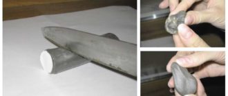
Today, the use of aluminum wiring is prohibited by the PUE, and the welding connection method is still popular. The point is this: after carefully twisting the stripped wires, the contact of the welding machine is briefly applied to the end point.
Usually this is a compact device of low power. It is used by almost all professional electricians. Works on the principle of a spot welding spotter. It will not be possible to light an arc, but the metal at the point of application melts properly. The figure shows the simplest circuit that can be assembled at home.
The connection quality is more than sufficient. In addition to the total twist length (40–50 mm), the ball at the end forms a point with minimal resistance. An additional plus is that this twist will not unwind even when moving the wires inside the box.
If a welding machine is not available, we limit ourselves to ordinary twisting. Of course, we make the connection not with our fingers, but with the help of pliers. All ends of the conductor must be stripped (but not reduced in cross-section), the length of the bare part before twisting begins is at least 70 mm.
Twisting is done after the wires are finally secured in the box. If the cable moves, the connection may become weak. The result is sparking, overheating, and contact breakage. It will be good if there is no fire.
- As an option, after twisting, the wires are soldered in the junction box.
Important! There is a widespread opinion among amateurs: under load, the twist will heat up and the solder will melt. Firstly: a load capable of heating a conductor to the melting temperature of solder is unrealistic at home. Of course, provided that the circuit breakers are in working order. Secondly: heating during twisting occurs due to loose contact, and this can be solved by soldering.
The reliability is not much worse than with welding. In this case, there is no need to purchase (do it yourself) a welding machine, a fairly powerful soldering iron, or even a hair dryer.
Tip: Use the most powerful soldering tool possible. It is better to expose the contacts to high temperatures for a short time than to heat the contacts slowly and for a long time with a weak heater.
During heating, monitor the condition of the insulation. If it starts to melt, take a break until it cools completely. Immediately after soldering, do not move the wire; allow both the solder and the insulation to cool.
Use refractory solders; these alloys have higher strength characteristics.
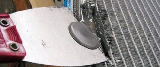
- Crimping. From the point of view of electrical conductivity, the quality of contact is no better than that of conventional twisting. But the strength of the connection increases significantly. If it is not possible to weld or solder the twist, crimp it using a special sleeve.
You can get by with pliers, but a special tool is still more reliable. There are bushings for parallel splicing of wires, and there are for fixing twists. There is no fundamental difference. If there are two or three conductors, parallel crimping is suitable. For larger quantities - crimping after twisting.
In fact, the methods discussed above are a modernization of the good old twisting. You should not be skeptical about the issue. Due to poor contact in the junction box, many fires occurred and damage to household appliances was caused. Therefore, when repairing electrical wiring in your home, use technical means to improve contact in the twist to the maximum.
Modern methods of connecting wiring in a box
The so-called quick fix pads. These products are widely offered in online stores and building materials markets.
Indeed, such devices make installation quick and convenient. The appearance of the connection is also pleasant. Therefore, such “electric clips” are loved by electricians who perform custom work.
However, this method has serious drawbacks. Let's make a reservation right away: the manufacturer does not promise high connection power: the characteristics are on the case. For an LED lamp, connecting a computer or TV - just right. But a refrigerator, electric stove, boiler cannot be connected through such a distribution box.
The contact area in such “quick releases” is small; the pad is connected to the conductor tangentially. With a light load, the current does not heat the surface too much. And when a serious consumer is connected, sparking, heating, and burning out of the connection will begin.
Conclusion
With all the variety of ways to connect wires in a box, traditional twisting remains the most reliable. Welding or soldering significantly improves contact.
No serious equipment is required; all work can be completed with basic electrical engineering skills.
Source: https://ProFazu.ru/provodka/montazh/soedinenie-provodov-v-raspredelitelnoj-korobke.html
Correct connection of electrical wires: do-it-yourself soldering
There is wiring in every house. And the correct connection of wires is part of the safety of the electrical network and its trouble-free operation.
Installation of electrical wiring in an apartment or cottage involves connecting the wires of distribution boxes and switchboards. The safety of the electrical network and its trouble-free operation depend on how correctly and efficiently all connections are made.
Correct connection of electrical wires
Methods for connecting electrical wires
Electricians use the following methods for connecting wires:
- twisted;
- soldering;
- using terminal blocks;
- crimping;
- with bolts;
- plastic PPE;
- “Wago” – spring terminals;
- "nuts" made of plastic.
The choice depends:
- from the material of the wire (cable) cores;
- on the operating conditions of the electrical network (external or internal wiring, hidden or laid openly);
- from the cross-section of the connected conductors;
- on the number of cores in one connection.
The connection of the distribution box wires must be made in such a way as to ensure reliable contact and avoid heating the wires. Here is an overview of the above methods for connecting current-carrying conductors.
Features of using terminal blocks to connect electrical wires
The terminal block consists of a plastic housing, a brass or copper bushing with threads and screws located on both sides.
This device allows you to:
- save on electrical equipment: the terminal block is cheaper than other connectors;
- connect the wires securely;
- connect cores of dissimilar metals (copper with aluminum);
- reduce installation time.
Disadvantages of terminal connectors:
- unsuitability for connecting more than two conductors;
- difficulties when connecting aluminum conductors: if the screw is over-tightened, the metal may break;
- unsuitable for use with multi-core wires.
The connection of electrical wires in the terminal block is carried out as follows.
The outer insulation is partially removed from the cables and the cores are exposed. The length of the bare conductor depends on the size of the terminal.
The length of the wire section without insulation is checked, for which you need to unscrew the terminal screw and insert the core completely into the hole. The excess is cut off with side cutters.
To improve contact, the copper wire is tinned. The connected cores are inserted into the terminals one by one and clamped with screws in several stages.
The reliability of the connection is checked.
Tip: in order to remove the insulation without damaging the core, it is recommended to use a special tool. If this is not available, only the surface layer of insulation is cut in a circle with a sharp knife, after which the wire should be bent along the cut line. After breaking, the insulation is removed with a light movement of pliers.
We use spring terminals to connect electrical wires
The connection of conductors with spring terminals is carried out using springs that press the contact plate to the metal of the core. The mechanism is driven by a special lever.
Wago type terminal connector
The Wago technology has a number of advantages over other installation methods:
- allows you to connect aluminum wires with copper;
- can be used to connect more than two wires;
- allow you to switch wires in small junction boxes;
- installation is carried out efficiently and in the shortest possible time;
- conductor cores are not damaged;
- After installation, it is possible to check the continuity of the circuit using a device probe or indicator through a hole in the housing.
In order to connect the wires using Wago terminals, it is necessary to remove the insulation so that the exposed wires are not visible, then insert the wires into the connector sockets and press the levers until they stop.
Note: Wago spring terminals are available in reusable and disposable versions. The latter, if it is necessary to repair the connection, are cut off, after which new connectors are installed.
Connecting conductors using PPE caps
The PPE cap is screwed onto the connection clockwise
The abbreviation PPE means “connecting insulating clamps”. The connector is designed as a spring located in a plastic housing. The spring securely holds the wires together, which creates reliable contact. Advantages of this method:
- the ability to mark wires using colored caps: the “phase” conductors connect red PPE, “zero” – blue or white, “ground” – yellow or green;
- fire protection: connector bodies are made of non-flammable plastic.
Important: connecting copper and aluminum wires using PPE is not allowed.
Crimping with sleeves
Connecting conductor cores with sleeves
The method consists of putting a metal tube (sleeve) on the cores freed from insulation, which is crimped with press pliers. As a result, the conductors are tightly connected to each other. The connection point is isolated.
Important: connections of aluminum and copper conductors may only be made using sleeves specially designed for this purpose.
Welding or soldering technology allows you to obtain a reliable connection of wires
The disadvantage of this method is the inability to monitor the integrity of the network after installation and isolation, as well as the non-repairability of such a connection. Additionally, a DIY soldering torch is dangerous to use.
An alternative to soldering wires is to weld them. The process involves the use of a welding machine.
Wire welding technology
When connecting copper wires this way, it is recommended that you try out a DIY copper wire soldering transformer before you begin. It is important to know that copper is smelted at a temperature of 1080 °C, but above 300 °C this metal becomes brittle.
In the absence of a special soldering device, use a conventional inverter welding machine. The step-by-step process of welding wires is as follows.
Up to 10 cm of insulation is removed from the ends of the wires.
The cores of the connected wires are tightly twisted together. The result should be twists approximately 5 cm long.
The ground cable of the inverter apparatus is connected to the twist closer to its beginning.
The current adjustment knob is set in the position from 30 to 90 A (at a voltage of 12 - 36 V): the value is selected depending on the cross-section of the wire and their number.
The carbon electrode of the welding machine briefly (no more than 2 s) touches the twist so that an arc is formed. As a result, a welded monolithic joint is formed at the tip of the twist. After complete cooling, the connection is insulated with heat shrink tubing or adhesive tape.
At the ends of the cores connected by welding, a monolithic alloy is formed
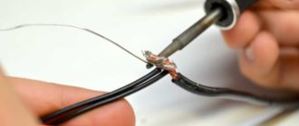
Connecting electrical wires by soldering
Soldering copper wires is an old, proven method that allows you to obtain a reliable electrical connection. The technology allows the installation of monolithic and stranded wires of various sections. There can be several conductors in one connection.
The work is performed using the following technology.
The insulation is removed from the ends of the connected conductors using a special device (approximately 5 cm).
The strands are tightly twisted together manually or using pliers (depending on the number of strands and their sections).
The twist is treated with flux or rosin.
This is necessary to improve the quality of soldering. On an open fire (using a gas burner or a gasoline blowtorch), a cup soldering iron (futorka) is heated red-hot. The cup of the futor is filled to the brim with tin-lead solder grade POS 30, POS 40 or POS 61.
The solder is heated to the point of fluidity.
The twist is briefly (up to 1 second) completely dipped into the futor cup, as a result of which the solder should completely cover the exposed wires.
After natural cooling, the twist is insulated with PVC adhesive tape or a plastic cap.
Important: soldering of wires should be done with safety glasses and tarpaulin gloves. During work, fire safety rules must be observed.
Soldering copper wires is performed as shown in the video.
Connecting wires with simple twisting
Wire connection diagrams in a distribution box for low-power electrical networks can be implemented by simple twisting without the use of additional fixing means. In this case, it is important that the twisting step is as small as possible, and its length is at least 20 mm. Only cores made of homogeneous metals are connected in this way: copper - with copper, aluminum - with aluminum.
It is not allowed to use this installation method in damp rooms and in wooden houses.
After twisting, the wire connection should look as shown in the photo
Walnut clamp
For connecting wires with a cross-section of 4 square meters. mm and it is more convenient to use a “walnut” clamp. It consists of a pair of specially shaped plates that are pressed together with screws at the corners. Advantages of the method:
- ease of connection;
- the ability to connect copper conductors with aluminum ones;
- comparative cheapness of materials.
Important: the “walnut” clamp is not used in distribution boxes (dimensions do not allow). To ensure reliable contact, the screws must be tightened from time to time.
Using a bolted connection to connect electrical wires
To connect large cross-section wires, as well as to install grounding elements in an electrical panel, a bolted connection is used. The ends of the wires, freed from insulation, are screwed onto the bolt threads in a clockwise direction. The connection is pressed with a washer with an engraver and a nut, after which the bolt is isolated.
In conclusion, we suggest that you familiarize yourself with the training video (master class with expert comments).
published econet.ru
If you have any questions on this topic, ask them to the experts and readers of our project here.
Source: https://econet.ru/articles/185364-pravilnoe-soedinenie-elektricheskih-provodov-payka-svoimi-rukami
Soldering wires!!! Should be avoided
Hello, dear guests and regular readers of the site http://zametkielectrika.ru.
In one of my articles, I introduced you to all the permitted methods of connecting wires, which are recommended to us by the Electrical Installation Rules (PUE).
Today I would like to make a small correction, namely, to focus your attention on this connection method, such as soldering wires .
I remind you that on January 1, 2013, GOST R 50571.5.52-2011 came into force, which states that when connecting wires to each other or to clamps (terminals) of electrical equipment, for example, to protection devices, it is necessary to maintain their electrical continuity and mechanical protection and strength.
When choosing means of connecting conductors, you need to take them into account:
- quantity
- section
- form
- material (copper, aluminum)
- isolation
Why should you limit your use of soldering wires?
The answer to this question is found in the current regulatory documents. Below I will give you a few excerpts from them:
All of the above points of the current normative and technical documentation limit (I specifically underlined) the use of soldering as a method of connecting electrical wires, due to its disadvantages:
- insufficient mechanical strength
- contact resistance increases over time
- Chemical corrosion occurs from flux residues
- reduced electrical conductivity
- inability to provide the necessary sanitary and hygienic conditions during soldering at the installation site
- environmental friendliness
Here is another excerpt from GOST 10434-82 about contact electrical connections:
From this we can conclude that when connecting two or more copper wires, as well as when connecting a soldered (“tinned”) wire to a protection device, the permissible temperature of the contact connection can reach 300 ° C, and this exceeds the initial melting temperature of soft PIC (tin solder -lead), which ranges from 180-240°C.
In such cases, it is necessary to use additional mechanical fastening, for example, a bandage, therefore, when a short circuit current flows through the contact solder (“tinned”) connection, the solder will melt, but after disconnecting the damaged circuit, the contact solder (“tinned”) connection will be mechanically restored, in connection with the use of a bandage that will prevent the molten solder from draining.
To be honest, it’s hard for me even to imagine how this can be done in practice.
Therefore, I turned to the local energy inspector with this question, especially since the day before we were going to hand over a project to him - a major overhaul of the electrical wiring of a residential apartment building.
The answer was obvious: either do not use soldering at all, or use PPE to connect the wires by soldering. As I understand it, PPE performs the function of additional mechanical fastening.
That's what we did. Wago terminals were used on the lighting circuit, and “solder for PPE” was used on the power circuits. We figured out this issue, and what to do with connecting flexible (multi-core) wires to protection devices.
Is it necessary to solder stranded (flexible) wires to connect them to protection devices?
The answer to this question is available in GOST R 51321.1-2007:
There is no need to explain here, everything is clear.
One has only to add that if the terminals of protective devices (circuit breaker, SPD, RCD, etc.), electric meter or connecting terminals have a socket design, then soldering of the ends of a flexible stranded wire is not required, because A clamp of this type does not squeeze or push the wire out from under the head of a screw, washer or plate, but on the contrary, it even securely squeezes and presses it. In other cases, it is better to use crimping.
Source: http://zametkielectrika.ru/pajka-provodov/
How to solder twisted copper wires
Electrical wiring in the room must be safe and convenient to use.
If you strictly follow this rule, then each energy consumer (chandelier, TV, computer, refrigerator) must have its own protection device against short circuits or overheating of the wiring.
You can run a separate cable from the personal circuit breaker for each outlet and switch. Two more criteria oppose this: rationality and economy.
on this topic
Source: https://steelfactoryrus.com/kak-payat-skrutku-mednyh-provodov/
Rules for soldering copper wires
One of the best ways to connect copper wires is soldering. It provides high strength and electrical conductivity. At the same time, soldering is easier to carry out than welding, and it is more reliable than simple twisting. Although the wires in junction boxes are often connected using self-clamping terminals such as WAGO, soldering techniques will not hurt any electrician to know.
You can learn how to solder copper wires in a few minutes, having all the necessary materials and equipment.
The essence of the process
The essence of the soldering process is that metals are joined together using an alloy that has a melting point lower than the melting point of the substances being joined.
During soldering, materials are heated to the melting temperature of the solder. This ensures very strong adhesion (sticking) - the property of materials to adhere to each other at the molecular level.
However, the main parts do not melt and mix with the solder material, as happens when welding using filler material.
Soldering iron and solder
Soldering irons are traditionally used for soldering copper wires. There are several types of them, including electric and gas. Soldering of copper wires is carried out using an electric soldering iron with a copper tip. This tool consists of a copper rod, sometimes nickel plated, that is mounted in a heating element housing.
The heating element operates on direct or alternating current. The supply voltage can vary from 12 to 220 V. For soldering copper wires of electrical wiring in the house, the most common soldering iron with a power of 60 W is suitable. If you need to solder thin wires of an electrical appliance, then a less powerful tool will do. It is important that it heats the copper material well and melts the solder.
To ensure high soldering quality and joint strength, it is necessary to remain still while the molten solder cools. You can hold the wires with your hands, but it is more convenient to use tweezers or clamps.
Tin-lead solder is used for soldering copper wires. Most often this is POS-61, but you can also take POS-40. The marking indicates the composition - tin-lead solder with a tin content of 61%.
Solder is usually produced in rods with a diameter of about 8 mm or in the form of solder wire with a diameter of 2 mm. General purpose solder is often used for soldering copper wires, which looks like a hollow tube of tin-lead alloy. Inside such a tube there is flux powder.
Application of flux
In order for the solder and the wire material to interact with each other, and the connection to be high-quality, the wires must be cleaned of the oxide film and only then soldered. For cleaning, you can use sandpaper, and for subsequent processing, use a special substance - flux.
Flux will not only clean copper wires, but will also create a thin protective film that prevents oxidation of the material.
It is allowed to use both solid flux - pine rosin, and liquid - various types of soldering acids or a homemade composition.
Sometimes, in order to correctly and firmly solder copper wires to each other or to any metal object, they use only liquid flux. You can prepare it by dissolving ordinary pine rosin in ethyl alcohol.
Soldering acid is prepared independently by dissolving zinc granules in hydrochloric acid in the proportion of 412 grams of zinc per 1 liter of acid.
But it’s better to buy ready-made flux that meets all quality standards, since bringing acidic compounds to copper wires is undesirable.
How to solder correctly
To reliably solder copper wires, you need to prepare a soldering iron. If you do not tin the tip before work, the solder will not stick, but will roll off the rod in balls. This happens because the tip is covered with a layer of copper oxide and carbon deposits formed during previous soldering.
Preparing the soldering iron
For ease of work, some specialists sharpen the tip with a flat file to give it the shape of a spatula or flat screwdriver. The sharpening angle should be 45-60 degrees.
A non-burning tip (eternal) cannot be sharpened under any circumstances; special sponges are used for it.
The mechanically cleaned tip must be heated and then tinned. To do this, it is coated with flux.
If the flux is solid (rosin), simply immerse the tip in it. The rosin will melt and cover the heated surface. After this, you need to touch the solder bar with a soldering iron and heat it up. The molten solder will coat the tip, protecting it from further oxidation.
The procedure for tinning a soldering iron must be repeated as carbon deposits form on it. This happens because the temperature of the tip is much higher than the melting point of the solder, and over time it begins to burn. To reduce the likelihood of this happening, it is recommended to use a soldering iron with temperature control.
Preparing the wires
The copper wires to be connected also need to be prepared for soldering. First, remove the insulation from the ends at a distance of about 4 cm, strip them, twist them together and tinning them. Copper wires can be tinned as follows:
- heat the twist with a soldering iron;
- coat with flux;
- Apply a small amount of solder, spreading it over the surface of the wire.
The actions are similar to those performed when tinning a soldering iron tip. If you are going to solder stranded copper wires, then you must stock up on liquid flux, since it will be very difficult to cover the entire surface of the copper “hairs” with molten solid rosin. To get a quality connection, you need to heat the stranded wire and then dip it in liquid flux, which will wet the entire surface intended for soldering.
Further, soldering of stranded and single-core copper wires is carried out in the same way. The two or more conductors being joined are heated together and solder is applied to them. After applying it, it is necessary to ensure that the joint remains motionless while it cools. It is not allowed to accelerate cooling by wetting it or blowing air on it.
Copper and aluminum connection
When connecting copper and aluminum wires by soldering, you can encounter many difficulties, which can only be overcome by using alternative connection methods.
The fact is that both aluminum and copper are covered with an oxide film in air.
And if these films themselves do not affect the state of the conductor in any way and even provide fairly good conductivity, then when combined they contribute to the occurrence of a powerful chemical reaction.
Under the influence of moisture contained in the air, at the point of contact between aluminum and copper oxides, the process of electrolysis begins, that is, an electric current is formed due to the fact that the ions of both materials have different electrical potentials.
Electric current is the movement of charged particles - ions, and during their movement, metals at the point of contact are destroyed. At the same time, aluminum is more destroyed. Destruction causes the contact to deteriorate, and subsequently the electrical resistance of the connection increases and it heats up. With severe corrosion, when direct contact between the two materials has already been lost, an electric arc occurs, which completes the destruction.
It is recommended to connect copper with aluminum only through a third, neutral material. Most often, steel terminal blocks or clamps are used for this.
Source: https://svaring.com/soldering/praktika/pajka-mednyh-provodov
Connecting wires by soldering during electrical installation
In this article I will look at the connection of copper wires in a junction box during electrical installation by soldering.
Despite the fact that I switched to Vago connectors, which significantly speed up the installation of electrical wiring, I still think that connecting wires by soldering is better. Now the welding devotees will attack me. But I won’t argue, I’ll just say that it’s more convenient for me, and the electrical and mechanical properties of such a connection are no worse than welding.
By the way, you know that 50-70 years ago radio equipment was assembled by welding. This applied to tube (there were no others) televisions and radios. And then we switched to printed wiring, which uses soldering. The soldering method requires higher technological preparation, but speed and ease of installation are everything.
So, I’m publishing a few photos illustrating the soldering of wires in a junction box. I will try to reveal all my secrets of such electrical installation. I hope my experience will be useful to my readers. Basically, for this purpose I write articles on SamElectric.
Connecting wires by twisting and soldering - what does the PUE say?
Let's start with the fact that twisting wires in electrical installations is prohibited. At least in the PUE, twisting is not allowed (PUE, Chapter 4.2). This can be explained by the fact that the quality of twisting depends very much on the experience, tool, and even the mood of the electrician. And there is no way to check this quality, you can only evaluate it “by eye” or test it with increased current.
Soldering is also not allowed, this is stated in the PUE there. This is motivated by the fact that in some emergency conditions the connection temperature can reach 300°C, the solder will melt and drain. Honestly, I can’t imagine how this can happen if the circuit breakers are installed with the required rating. But even if this happens, in my opinion, such wiring will need to be completely changed! And it won’t matter whether the solder melted or not.
As for crimping - yes, the method is good, but it requires additional equipment (press molds) and consumables (sleeves). The same goes for welding - you need a transformer (inverter) and graphite rods. And experience - how many times have I seen that the ball at the end of the twist fell off due to excess current, or did not grab all the wires in the twist due to low current.
Therefore, I believe that twisting followed by soldering is the best way to connect wires in junction boxes. The soldering iron is lightweight, the price is low, the solder and rosin are cheap.
Next - more about this hot smelling process)
Soldering twisted copper wires
Let's start from the place where the wires are twisted in the junction box.
1. Twisting the wires in the box
In the left box, the wires are twisted according to the electrical wiring diagram. In principle, many electricians stop there. And they are 90% right, it can be insulated, such wiring will last 100 years, we don’t need any more. But this is provided that in this distribution. the box will always be dry and the circuit breaker has been selected correctly. I recommend my article about choosing a circuit breaker - How to choose a circuit breaker.
I saw that in old boxes there was a twisted connection between aluminum and copper. These were twists from 50 years ago! And everything worked great! This is very risky, and such compounds will live for a long time if several favorable conditions are met. Such twisting is usually subject to severe criticism among electricians, and it is considered extremely unprofessional. But we’ll forgive you, especially since those who made such twists are already in another world, where there is no need to connect wires
Soldering wires in a junction box
We take out a soldering iron with a power of 65 or 100 watts. The power depends on the sum of the cross-sections of the wires being soldered. For example, if you solder 3-4 wires with a cross-section of 1.5 sq. mm, then a 65 W soldering iron will be enough. If the total cross-section of twisted wires is more than 10 sq. mm, then the soldering iron should be 100 watts.
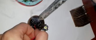
So, we take rosin in a piece or in a plastic jar. The wires should stick out with their tips facing up. We warm up the twist area and touch the rosin so that it melts and flows a little down the twist.
2. Application of rosin
This is especially visible on the central and right wires. Then we take the solder in the rod, heat the solder and the twist at the same time, tinning the twist.
It is better to use solder with rosin; there is a lot of this on sale now. The rosin is found inside the solder rod. If there is no rosin inside, you need to apply more of it to the twist beforehand, and more carefully control the soldering time and temperature. otherwise the rosin may simply evaporate.
3. Soldering twists in the junction box
We solder the wires. Tin the twist so that the solder penetrates into all places. In this case, the copper must be covered with solder over a length of 4080% of the twist length.
4. Wires are soldered
You must try not to overheat the soldering area so as not to damage the insulation. And in general, try to do everything quickly, automatically.
We cut off the ugly protruding ends of the soldered twists with side cutters (3-5 mm).
Soldered, insulate the soldering points with electrical tape (usually I use PVC of different colors). And that's basically it. You can wall the boxes.
5. Insulate solder joints
6. Lay wires in junction boxes
Isn’t it true that there is something mean-spirited in the word “flush”?))
7. Closed boxes. Flush
You definitely don’t have to worry about contact in such boxes; you can completely bury them under a layer of plaster. Although, it’s better, of course, to have access to the boxes, you never know – check, connect additionally, etc.
As cs-cs.net spoke on this topic: If at 2 o’clock in the morning you wanted to see how your twisting of copper and aluminum is doing, you should have access to the distribution box without any problems.
Poll on the topic of the article:
Source: https://SamElectric.ru/elektrika/soedinenie-provodov-pajkoj.html
Soldering wires in a junction box: copper wires, twist, tool and solder
Without exception, all electrical wiring diagrams provide for branching and connecting cables and wires. To do this, it is necessary to additionally install a distribution box, which is made of metal or polymer materials. However, installing the structure is not enough; it is important to know the technology for soldering twisted wires in the junction box.
General switching rules
The implementation of the soldering method is reminiscent of welding work, only an ordinary soldering iron is used, and not an inverter apparatus with electrodes. Before twisting, the cores must be tinned. To do this, heat up the soldering iron, immerse it in rosin and pass it over the areas stripped of insulation several times until a reddish tint appears.
To ensure quality work, you must first check the soldering iron tip. It is important that it is clean. If the surface is uneven and dirt has accumulated on it, it will be impossible to make high-quality solder. Contaminants are removed with a file, then its end is tinned again.
Advantages of soldering compared to other connection methods
Tool for removing insulation from wires - stripper
There are several ways to connect wires in a junction box, however, only soldering and welding differ in minimum contact resistance and monolithic connection. Anyone can solder wires at home. Welding requires experience and a special welding machine.
To carry out the work you will need the following set of tools:
- flux;
- a knife designed to remove insulating material;
- solder;
- side cutters;
- soldering iron;
- pliers or pliers;
- sandpaper.
You cannot begin work without first preparing all the necessary tools and consumables.
Soldering wires
Stripping the insulation from the wire
Tinning and soldering of cables in the distribution box is carried out in several stages.
- Removing the insulating layer.
- Stripping the wires until the characteristic shine of the metal appears.
- Maintenance.
- Twisting.
- Soldering.
- Isolation.
Before you start connecting the current-carrying wires, you need to analyze what length is required. The wires are cut so that when soldering the ends are located outside the junction box. Upon completion of the work, they are laid in any desired way.
Soldering wires in the junction box is prohibited. The stock in this case is also inappropriate.
To remove the insulating layer, a special tool is used - a stripper or a sharp knife. When working with a sharp knife, the movements should resemble whittling a pencil. It is forbidden to cut the insulating layer with pliers or side cutters; you cannot make circular cuts. Transverse damage will cause a break in the near future.
For a wire intended for soldering, stripping ranges from 1.5-3 cm. The number of turns is at least 2.
Main types of solder wire connections
Before soldering, the wires are thoroughly cleaned and tinned so that oxides do not appear on the surface of the conductors, which interfere with normal conductivity and increase resistance. Already tinned conductors are twisted using pliers or pliers.
Soldering twisted copper wires in a box has a similar algorithm. The twist must be tight, but not tight, otherwise the ends of the conductive wires may simply break off.
Finally, the twisted wires are soldered with a soldering iron so that the solder is covered with an even layer on all sides. The quality of the work depends entirely on how well the ends were stripped.
Selecting the power of the soldering iron
To perform high-quality work, you need to use fairly powerful soldering irons, at least 65 W. This is especially important when working with copper wires, since copper is a good conductor of heat, therefore, it removes heat from the soldering area. If the power of the device is insufficient, this can lead to “cold soldering” - the solder covers the soldered area unevenly, and the strength will be low.
The device should optimally heat the area for 1 minute and no more, the surface of the solder at the end of the work should be smooth and have a uniform shine.
Solder type
There is a wide variety of solders, the main ones are listed in the table.
| Solder grade | Compound (%) | Tensile strength (kg/mm) | Melting temperature | Application |
| POS-30 | Lead – 70 Tin – 30 | 3,2 | 266 | For soldering and tinning of parts made of steel, copper and their alloys |
| POS-40 | Lead – 60 Tin – 40 | 3,8 | 238 | For soldering and tinning of contacts and parts in radio equipment made of galvanized steel |
| POS-90 | Lead – 10 Tin – 90 | 4,9 | 220 | For soldering and tinning of medical instruments and metal utensils |
| POS-61M | Copper – 2 Lead – 37 Tin – 61 | 4,5 | 192 | For soldering and tinning of printed conductors and copper wires |
| POS-61 (tertiary) | Lead – 39 Tin – 61 | 4,3 | 190 | For tinning and soldering of live parts made of bronze, brass and copper with sealed seams |
| POSV-33 | Bismuth – 33.3 Lead – 33.3 Tin – 33.3 | – | 130 | For soldering parts made of constantan, brass and copper with a sealed seam |
| POSV-50 (Alloy Rose) | Bismuth – 50 Lead – 25 Tin – 50 | – | 94 | For processing parts that are susceptible to overheating |
| Alloy d Arce | Bismuth – 45.3 Lead – 45.1 Tin – 6.9 | – | 79 | For the production of fuses, tinning and soldering of parts susceptible to overheating |
| Wood's alloy | Cadmium – 12.5 Bismuth – 50 Lead – 25 Tin – 12.5 | – | 68,5 | An important feature is that it is toxic. Designed for the manufacture of fuses, tinning and soldering of parts susceptible to thermal effects |
The last three grades have a low melting point and low alloy strength.
Protecting the soldering area from oxidation
Flux is used to protect the soldering area from oxidation by oxygen. When working with copper, the following are most often used:
- Rosin, it contains only pine rosin.
- LTI-120 includes triethanolamine (1-2%), aniline hydrochloride (3-7%), ethyl alcohol (66-73%), rosin (20-25%).
- The composition of alcohol rosin includes ethyl alcohol (60-70%) and rosin (30-40%).
The simplest, most budget-friendly and at the same time widespread version of flux is ordinary rosin. The only difficulty that may arise when working with a substance is its solid state of aggregation.
Soldering and tinning technology
When starting to solder or tinning wires, it is important to place the wires horizontally so that the soldering iron tip touches all sides without obstruction. Some “experts” recommend placing conductive wires vertically, but this should not be done, since drops of solder may begin to spread.
Before tinning, the wires are heated with a soldering iron and, at the same time, they touch the heating area with a piece of rosin until it begins to melt. If liquid flux is used, it is applied first before heating begins. After tinning, the wires are twisted.
Soldering technology is slightly different because it requires a larger amount of solder. Flux is applied to the conductive wires and heated with a soldering iron until the molten drop is evenly distributed. If necessary, the procedure can be repeated.
Soldering with a torch and crucible
Wire soldering device
If there is a large scope of work ahead, it is advisable to use crucibles, which are a hollow metal cylinder equipped with a handle for filling with molten solder. This device can be heated with a gas burner or used as an attachment for a powerful soldering iron.
The container holds a small amount of molten solder; while it hardens, a person has time to make several twists.
Precautionary measures
Caution should be exercised during work as molten solder can cause severe burns if it comes in contact with the skin. All brands of solder contain lead, the vapors of which are toxic to humans. To prevent poisoning, you need to wear a respirator when working.
When soldering wires, it is prohibited to use acid-containing active fluxes, since they require complete removal after completion of the work. Flux residues have a destructive effect on all materials; soldering acid and zinc chloride are especially aggressive for copper.
In general, the work should not cause difficulties, the main thing is to familiarize yourself with the execution technology in advance, prepare all the consumables and tools.
Source: https://StrojDvor.ru/elektrosnabzhenie/kak-i-chem-spayat-provoda-v-raspredelitelnoj-korobke/
How to choose the right soldering iron and learn how to solder wires
Soldering is the primary method of electrical and mechanical joining of both parts and wiring. But despite the apparent simplicity of the process, soldering is quite complex and painstaking. That is why, before picking up a soldering iron, you need to have a good idea of what, why and, most importantly, how to solder wires.
Tools and accessories
Soldering, like any other technical process, involves the use of certain tools and accessories. You will need a few tools: a soldering iron, a knife, pliers, a file, sandpaper.
There are even fewer accessories - soldering flux and alcohol or gasoline are enough. Nevertheless, all of these are important components of the process and the choice of both must be taken extremely seriously.
Both the mechanical and electrical reliability of the soldered joint will depend on the quality of the soldering iron and the availability of the necessary accessories.
Selecting and preparing a soldering iron
This is perhaps the most crucial stage. A poorly chosen or improperly prepared tool will not produce high-quality soldering.
Power and type
The main criterion for choosing a soldering iron is its power. The industry produces instruments with power from 10 to 200 W and higher. The former can be the size of a fountain pen, the latter look like a natural hammer of impressive size.
Electric soldering irons with a power of 30 (left), 60 and 200 W.
All that remains is to decide which soldering iron to choose for soldering wires. Here everything will depend on the operation being performed, or more precisely, on the thickness and massiveness of the parts that need to be soldered. The more massive the parts, the greater the heat capacity the tool should have. An approximate dependence of the recommended soldering iron power on the task being performed can be presented in the following table:
- 15-25 W – small radio elements, microcircuits, conductors with a diameter of up to 0.3-0.5 mm;
- 30-40 W – large radio elements, wires with a diameter of up to 1 mm, including multi-core ones;
- 40-60 W – fairly large parts, conductors with a diameter of up to 2 mm;
- 100 W – massive parts, wires with a diameter of up to 3-4 mm;
- more than 100 W – power wiring with a diameter of more than 4 mm.
If you don’t have a soldering iron with the necessary characteristics at hand, you can take a slightly larger one in power, but not vice versa. With a massive device, it is possible to solder thin wires with a certain skill, but with a small and low-power thick one, it is almost never possible. Ideally, your household will have several electric soldering irons of varying power.
But what to do if there is no soldering iron of the required power or if it does not exist in nature at all? Trying to solder busbars into a pencil thick with a 100-watt soldering iron? In no case! In this situation, regular fire will help.
Place the parts prepared for soldering, for example, in the flame of a household gas burner or alcohol lamp and solder. Additional heating will help to perform high-quality soldering even with low-power tools.
The only thing is, when heating the wires over an open flame, do not overdo it - a little additional heating is enough.
Separately, it is worth noting the so-called “pistol” or pulse soldering irons, which were widely used, and even today are in service with craftsmen on the road.
A modern version of a pistol soldering iron.
At first glance, the advantages of such a device are obvious - it heats up instantly and cools down just as quickly. But this feature is convenient only for a narrow circle of specialists - on-call specialists. He came, took it out of the suitcase, poked it, put it in the suitcase, took the money and left. But anyone who has seriously worked with such soldering irons knows very well their shortcomings.
Source: https://pochini.guru/sovety-mastera/kak-payat-provoda
Soldering twisted wires in a junction box
When I need to connect copper wires in a junction box, I twist and solder them. However, at the moment there is a lot of debate about reliability: some claim that the soldered connection is the most reliable, while others criticize soldering and recommend spring terminal blocks. It is worth noting that the supporters of the soldering iron are experienced, Soviet-trained electricians.
Today we will not find out which is better - in my opinion, an objective assessment of the quality of connections will be a comparative test at extreme currents, perhaps in the future we will conduct a similar test. But now let's talk about how to twist wires in junction boxes and actually solder them.
I would like to note: despite the fact that the process is simple and easy to master, it must be performed with care and accuracy. After all, all fires, as a rule, are caused by poor contact in one place or another.
Tool
To perform all operations we need the following tool:
Soldering iron 100-150 W with a copper tip. Ordinary, without frills in the form of a fireproof sting and other things. The sting can be straight or curved.
We will also need side cutters (nippers), pliers (pliers) and a construction knife. When working with thick twists, where, for example, 4 mm² cores will be present, additional pliers will be needed.
An optional tool includes pliers for stripping insulation: you can do without them, but with this tool things go faster.
Solder selection
Choosing the right solder for soldering twists is the most crucial moment. The final result depends on the solder. In the process of using different brands of solder, I tried to identify a pattern between the quality of soldering and the percentage of tin. However, such a relationship could not be found.
The only thing that can be said with complete confidence is that the solder must have flux inside. This is not surprising: the soldering method does not require the application of flux to the twists, but flux is necessary.
It is most convenient to use solder in a wire 1mm or so thick. It is sold in spools or plastic tubes.
By and large, you will have to choose solder by trial and error; I don’t see any other method. Well, here are a few examples of solders from several manufacturers:
This solder is well suited for soldering twists. And it’s better not to take the one below - it solders thin strands of 2 wires 1.5 mm² well, but it will only ruin thicker strands.
Here's another pretty good REXANT solder:
When choosing solder for the first time, the best option would be to buy a small tube for testing. Well, remember which of the purchased brands soldered well and which ones poorly. Actually, this is such a simple science.
In addition to solder, it is good to have a cleaner on hand - regular alcohol. Many copper strands, even new ones, are covered with layers of oxides or other deposits that make soldering difficult.
A good cleaner option is TAGS flux - it perfectly cleans the surface of copper conductors and in addition helps the soldering process.
Twisting wires
So, all wires are stripped of the general insulation that protects the entire cable. For each individual core, the twist length plus a small margin is taken - the base of the twist must be twisted with insulated cores. In general, you should try to put extra centimeters of wires in the box just in case.
Tip: always try to put more wires in the junction box, even taking into account the twists already made. Perhaps sometime in the future new lines will be added here or some repairs will be made. It would be good practice to consider the repairability of the boxes, even if you are confident in the reliability and quality of your work.
For the twists themselves, the cores are stripped to 10 centimeters - after twisting, the excess will be bitten off with side cutters. The final twist length of bare wires must be at least 4 cm. If installation is carried out in spacious junction boxes, the length of the twists can be increased to 7-8 cm. The main thing is that the twists fit into the box without bending.
But I got ahead of myself a little: before twisting the exposed wires, you need to wipe them thoroughly with a cloth soaked in alcohol or TAGS flux. After processing, the surface of the copper should have a uniform yellow color without dark areas - only then can twisting be done. If the veins are covered with too thick oxide, then before wiping they can be treated with fine sandpaper.
When soft, stranded conductors are present among the wires being twisted, they should be cleaned of oxides with special care.
Twisting is done with pliers so that a few centimeters of insulation also become part of the twist. You should tighten it with sufficient force, but you must not overdo it and not break any of the wires. Here it is recommended to first practice on test twists and “feel” the material.
When twisting a large number of wires or when the cross-section of the wires is large (4 mm² for example), the base of the twist must be held with additional pliers.
When the twists are twisted, they need to be shortened with side cutters to the length we need. Shorter than 4 cm is not recommended.
The junction box is twisted, you can start soldering.
Soldering
While the soldering iron is heating up, you need to “apply” solder to the twists. To do this, solder wire is wound onto each twist in increments of 1-3 mm. The winding pitch depends on the total thickness of all twisted wires and is found experimentally. The solder should be wound tightly so that it fits as tightly as possible to the copper surface.
If the twist contains stranded conductors, then more solder should be wound than usual. Stranded wires require much more tin - you need to take into account the number of flexible conductors in the total volume.
Using a heated soldering iron, touch the edge of the twist and wait until the solder melts. When melting the solder, we move the soldering iron to the base - the solder should melt before the soldering iron reaches its melting point. Key point: the soldering iron heats the metal, and the metal in turn melts the solder. By the way: it is not necessary to move the soldering iron from the edge to the base of the twist; you can do the opposite - from the base to the edge.
The solder should fill all the voids between the conductors and solder all the twists. Visually - the solder should be visible from all contacts of the cores with each other. Small strands are completely covered with solder, while larger ones are covered with solder where the cores touch each other.
Molten solder will definitely drip down, so you need to take all necessary measures to protect both yourself and the surrounding area.
If there are doubts that the solder has filled all hard-to-reach places, then soldering can be repeated again. To do this, you need to wipe the soldering area well with alcohol or TAGS, wind the solder and repeat everything. In such situations, the quality of the solder immediately becomes evident: the “crappy” solder will never be able to solder the second time.
After soldering, the strands are ready for insulation; they can be “wrapped” with electrical tape or heat-shrink tubing. Since we did not use soldering acid or other aggressive fluxes, there is no need to wash the soldering areas. When laying them in place, you should avoid bending the soldered areas.
In conclusion, I would like to say that soldering connections in boxes is a fairly simple matter. However, you will have to practice a little first and perhaps try several different solders.
Source: https://yserogo.ru/remont/payka-raspredkorobok.html