DIY choke for a welding machine
A choke is the industrial name for an electrical element such as an inductor. This device has a wide range of applications, in particular, a powerful choke can be used to improve the performance of a semi-automatic machine or inverter for welding.
Principle of operation
The main property of an inductor, which is a magnetic circuit wound under certain conditions around a ferromagnetic core, is the stabilization of current strength over time.
Simply put, voltage applied to the coil causes a smooth increase in current output. Changing the polarity leads to the same smooth decrease in current.
The main factor is the condition that the current passing through the inductor cannot sharply increase or decrease. This is precisely what determines the value of using a choke for welding - resistance compensation allows you to avoid sudden jumps in amperage.
This allows you to protect against accidental burning of the workpieces being welded, reduce spattering of the melting metal and accurately select the current parameters for welding for a given metal thickness. The chances of getting a good weld using a welding choke are much higher.
The parameter that determines the current change coefficient is inductance. It is measured in H (henry) - in 1 second at a voltage of 1 V, only 1 A can pass through a choke with an inductance of 1 H.
The number of turns on the coil directly affects the amount of inductance. It is directly proportional to the number of turns squared. But if you need to make a welding choke with your own hands, then it is not necessary to calculate the exact number of turns.
Since the parameters of welding machines for household use are mostly standard and well-known, a welder will only need to use the instructions below to make a choke with his own hands.
Purpose
In an inverter for welding, a choke is needed to create an electric arc on the electrode. Ignition occurs when a certain voltage level is reached.
The welding choke increases the resistance, which shifts the phases between current and voltage and allows for smoother ignition. This fact in itself often allows one to avoid burning through the workpiece, especially if parts made of thin sheet metal are welded.
A smooth change in current makes it possible to avoid damaging the workpiece by abruptly applying too much power, to optimally set the arc temperature and, accordingly, to prevent metal spattering while maintaining the required processing depth.
Another valuable property is its partial protection against unstable voltage in the network.
A choke for a welding inverter greatly facilitates ignition of the electrode, which should light up at a higher voltage than the inverter produces.
An example is the MP-3 electrode, which must have a voltage of 70 V to ignite. An output choke for welding can make working with this electrode much easier for an inverter, which produces only 48 V at idle.
This occurs due to the phenomenon of self-induction. The device induces EMF (electromotive force), which causes air breakdown and flashing of the welding arc, as soon as you bring the additive a few millimeters from the metal surface.
The choke for welding is connected to the secondary winding of the transformer in the machine. It can be used in devices of any type - both home-made and factory-made, operating on any principle - inverter, with a step-down transformer, and the like.
Materials for production
The choke for retrofitting a semi-automatic device or inverter can be assembled with your own hands, using structural elements from old equipment - tube TVs, old street lamps and other devices that have a transformer.
Structurally, it consists of a core made of a material that conducts a magnetic field, but does not conduct electric current, or is reliably insulated, and three layers of windings separated by a dielectric.
As a basis for the core, either a special material is suitable - ferrite, which has these properties, or a yoke (horseshoe) from an old transformer. Winding of the device for welding is done with aluminum or copper wire with a cross-section of 20-40 mm.
If aluminum is used, the wire cross-section must be at least 36 mm; copper wire can be thinner. A flat copper busbar with a cross-section of 8 mm is suitable.
The dimensions of the core should allow winding approximately 30 turns of a busbar of a given section, taking into account dielectric spacers. A core from the step-up transformer of the Soviet TV TCA 270-1 is recommended.
Sequencing
When the necessary tools and materials are prepared, you can begin to manufacture the throttle for welding. The algorithm of actions is as follows:
- disassemble the transformer, clean the coils from traces of old windings;
- make gaskets from fiberglass, cardboard impregnated with bakelite varnish, or other suitable dielectrics, which will subsequently play the role of an inductive (air) gap. They can simply be glued to the corresponding surfaces of the coils. The thickness of the gasket should be 0.8-1.0 mm;
- wind a thick copper or aluminum wire onto each coil. You should focus on a round wire made of aluminum with a cross-section of 36 mm or copper with a similar ohmic resistance. Each “horseshoe” is covered with 3 layers of 24 turns each;
- lay a dielectric material between the layers - fiberglass, cardboard impregnated with bakelite varnish or another dielectric. The gaskets must be reliable, since a choke of this design is prone to self-breakdown between windings. If the resistance between the windings is lower than the air resistance between the electrode and the additive, then a breakdown will occur between the windings, and the welding device will be irreversibly damaged.
Winding must be done evenly, without overlaps, strictly in the same direction, so that the “bridge” between the coils is on one side of the future inductor, and the input and output contacts are on the other.
In case of an error, the jumper can also be installed askew. It is important that its installation turns coils with different winding directions into coils with the same direction in fact.
Power on and check
The choke for welding is connected to the system between the diode bridge and ground - a contact that connects to the material being welded. The output of the diode bridge is connected to the input of the inductor, to the output of the assembled inductor - respectively, a ground contact.
The entire assembly for welding must be tested on a piece of metal of the same chemical composition and thickness with which it is planned to carry out most of the welding work in the future. Quality indicators are:
- easy electric ignition;
- arc stability;
- relatively weak crackling sound;
- smooth combustion without strong splashes of melt.
Please note that the introduction of this element into the design of the welding machine leads not only to stabilization of operation, but also to a slight drop in current strength . If the inverter or semiautomatic device begins to cook worse, it means that the current strength has dropped.
The choke needs to be disconnected and a few turns removed from each coil. The exact number of turns in each specific case is selected empirically.
Source: https://svaring.com/welding/prinadlezhnosti/drossel-dlja-svarki
DIY choke for DC welding
It is difficult to imagine, in our time, any work with metal without the use of a welding machine. Using this device, you can easily connect or cut iron of various thicknesses or dimensions.
Naturally, to perform high-quality work you will need certain skills, but first of all you need the welder itself.
Nowadays, of course, you can buy it, as well as, in principle, hire a welder, but in this article we will talk about how to make a welding machine with your own hands.
Moreover, with all the wealth of choice of models, reliable ones are quite expensive, and cheap ones do not shine with the quality of the work performed. But even if you decide to buy a welding machine, reading this article will help you choose the machine you need. There are several types of welders: direct current, alternating current, three-phase and inverter.
In order to determine which option you need, let’s consider the design and structure of the first two, which you can assemble with your own hands at home without any specific skills.
AC
This type of welding machine is one of the most common options, both in industry and in private households.
It is easy to use and, compared to others, can be made quite easily at home, as evidenced by the photo below.
To do this, you need to have a wire for the primary and secondary windings, as well as a transformer steel core for winding the welder. In simple words, an AC welding machine is a step-down transformer.
The optimal voltage when operating a welding machine assembled at home is 60V. The optimal current is 120-160A. Now it’s easy to calculate what cross-section the wire should have in order to make the primary winding of the transformer (the one that will be connected to the 220 V network). The minimum cross-sectional area of the copper wire should be 3-4 square meters. mm, the optimal is 7 sq.
mm, because it is necessary to take into account voltage drops and possible additional load. We find that the optimal diameter of the copper core for the primary winding of a step-down transformer should be 3 mm. If you decide to take an aluminum wire in order to make a welding wire yourself, then the cross-section of the copper wire must be multiplied by a factor of 1.6.
It is important that the wires are in a rag sheath; you cannot use conductors in PVC insulation - when the wires heat up, it will melt and a short circuit will occur. If you do not have a wire of the required diameter, you can use thinner wires by winding them in pairs. But then it should be taken into account that the thickness of the winding will increase, and, accordingly, the dimensions of the device itself.
For the secondary winding, you can use a thick stranded copper wire - the same as the core on the holder.
The first step is to make a transformer core for a homemade welding machine. The best option would be a rod-type core as shown in Figure 1:
This core must be made from transformer steel plates. The thickness of the plates should be from 0.35 mm to 0.55 mm. Before assembling the core, it is necessary to calculate its dimensions, this is done as follows: firstly, the size of the window, i.e. dimensions c and d in Figure 1 must be chosen such as to accommodate all the windings of the transformer, secondly, the roll area, which calculated by the formula Skren=a*b, must be at least 35 square meters. cm.
If Skren is greater, then the transformer will heat up less and, accordingly, work longer. It is better that the Skrena is equal to 50 square meters. see. Next, we proceed to assembling the plates of a homemade welding machine. It is necessary to take the L-shaped plates and fold them, as shown in Figure 2, until you can make a core of the required thickness. Then we fasten it with bolts at the corners.
Finally, it is necessary to process the surface of the plates with a file and insulate them by wrapping them with rag insulation.
Next, we proceed to winding the welding machine from the step-down transformer. First, we wind the primary winding, which will consist of 215 turns, as shown in Figure 3.
It is advisable to make a branch from 165 and 190 turns. We attach a thick textolite plate to the top of the transformer.
We fix the ends of the windings on it using a bolted connection, noting that the first bolt is a common wire, the second is a branch from the 165th turn, the 3rd is a branch from the 190th turn and the 4th is from the 215th.
This will make it possible to subsequently regulate the current strength during welding; the greater the number of turns in the primary winding, the higher the current strength of your welding device will be. Then we proceed to winding 70 turns of the secondary winding, as shown in Figure 4.
A smaller number of turns are wound on the other side of the core - where the primary winding is wound. The ratio of turns should be approximately 60% to 40%.
This ensures that after you catch the arc and start welding, the eddy currents will partially turn off the work of the winding with a large number of turns, which will lead to an increase in the welding current, and accordingly improve the quality of the seam.
We will also secure the ends of the winding with bolts to the textolite plate. Now your homemade welding machine is ready.
Having connected the holder and ground to the secondary winding, it is necessary to connect the network to the common wire and the wire extending from the 215th turn of the primary winding. If you need to increase the current, you can make fewer turns of the primary winding by switching the second wire to a contact with fewer turns. The characteristics can be reduced using a resistance made from a piece of transformer steel bent in the form of a spring and connected to a holder.
It is always necessary to ensure that the welding machine does not overheat.
This is how you can make a welding machine from a step-down transformer with your own hands. As you can see, the instructions are not too complicated and even an inexperienced electrician can assemble the device on their own.
DC
Some types of welding require a DC welder. This tool can be used to weld cast iron and stainless steel. You can make a DC welding machine with your own hands in no more than 15 minutes by converting a homemade product to AC. To do this, you need to connect a rectifier assembled with diodes to the secondary winding.
As for the diodes, they must withstand a current of 200 A and have good cooling. D161 diodes are suitable for this. Capacitors C1 and C2 with the following characteristics of 15000 μF and a voltage of 50V will help us equalize the current. Next, we assemble the circuit shown in the drawing below. Inductor L1 is needed to regulate the current.
Contacts x4 are for connecting the holder, and x5 are for supplying current to the part to be welded.
Now you know the basic principles of the design of welders and, using them, you can make a welding machine with your own hands, both constant and alternating current.
We also recommend watching the video lessons provided below, which will help you clearly see how to assemble a simple welder yourself from scrap materials.
Visual master classes
So, if you decide to make a welding machine at home, perhaps these video lessons will inspire you to make your own tool:
Also read:
Source: https://respect-kovka.com/drossel-dlya-svarki-postoyannym-tokom-svoimi-rukami/
How to make a choke for a DC welding machine
Welding with direct electric current is widely used not only in large-scale industries, but also in home workshops.
The modern market offers dozens (if not hundreds) of machines for welding using an electric arc, ranging from compact low-power welders to industrial high-performance units.
Regardless of the type of equipment used for electric welding, they all have one problem in common - an uncontrolled voltage drop, which makes igniting the arc and forming a seam difficult.
To solve this problem, craftsmen came up with a choke, which is introduced into the circuit with welding equipment. Beginner welders will immediately have many questions: “What is this part and how does it function? How to make a throttle for your device yourself? How to calculate the throttle correctly? In this article we will try to answer these and many other questions.
general information
What is a throttle for? This small part, connected to a circuit, ensures smooth ignition of the arc and maintains its stability even with voltage fluctuations, in addition, the metal practically does not spatter, the weld is of higher quality, you can fine-tune the device and weld thin metal without any problems.
The principle of operation is simple: the choke passes current through itself, accumulating it from the welding machine. The accumulated current is used to compensate for the lost voltage. Also, the bias choke provides the required current resistance if the voltage is too high.
It is not at all necessary to buy a throttle in a store, especially since it is far from a cheap purchase. This unit can be made independently.
Its design consists of a core and two windings with a cross-section designed to operate with a certain value of direct current.
This is why it will not be possible to make a universal choke, because a small part cannot cope with a powerful welder, and vice versa. So it is important to correctly calculate how many windings will be needed to work with a particular voltage.
Current adjustment
Adjusting the welding current is extremely important for proper operation and the formation of a high-quality seam. This can be done in several ways:
- Adjusting the current by changing the distance between the elements of the welding machine. The most popular way. To reduce the current, spread the cut transformer core apart. The induction will dissipate somewhat, and the current strength will become less. The larger the welding unit, the greater the ability to regulate the current, because the adjustment interval directly depends on the available size in the machine body.
- Adjusting the current on the transformer winding. In this way, it is possible to cut off part of the coil, thereby increasing the voltage value, allowing the current to flow along a shorter path. To weaken the current, the path must, on the contrary, be increased.
- Current adjustment using a steel spring with terminals fixed at a specified interval. This is a good adjustment method, it allows you to smoothly adjust the current, but there is one significant drawback - the spring gets very hot and is constantly under the master’s feet, and this is a gross violation of safety regulations.
If you introduce a choke into the circuit, most problems associated with current regulation will be solved. This seemingly small device is capable of fully compensating for the missing voltage or, conversely, acting as a resistance if there is too much voltage. The current adjustment by the choke occurs very smoothly and the welder does not need to hold a hot spring under his feet.
Throttle application
A choke for DIY welding works best on welding transformers. Our practice proves this. The choke quickly ignites the arc even with a significant loss of current, so it can be used without problems in the country or in a workshop with unstable voltage.
A separate feature is the ability to use a choke in conjunction with a rectifier. The inductor + rectifier combination is capable of increasing the electromotive force of self-induction. In the case of a semi-automatic machine, such a set of equipment allows you to easily ignite an arc even at a considerable distance from the metal surface.
DIY choke
Now let's figure out how to wind a choke for welding with your own hands and how to calculate the choke. To wind the choke correctly, you need to thoroughly know its structure and understand the principle of operation.
“General information” we briefly described the design and operating principle of this device. We have compiled a small step-by-step instruction, following which you can assemble the throttle.
The part you assembled is suitable for use in small production or home welding. So let's get started:
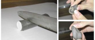
- First you need to find an old transformer, it will be our basis. Experienced craftsmen advise taking a booster element from a tube TV model “TSA 270-1”; it will act as a core. Similar models can be easily found at flea markets or searched online on online message boards.
- Then you need to disassemble the transformer. This is done simply: you need to cut the bolts or turn the heads at the top of the unit, then remove the coils.
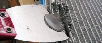
- The resulting “horseshoes” (as craftsmen call them) install special gaskets. They are made of thin cardboard and glued to the base of the “horseshoe”. Gaskets are needed to form an inductive gap.
- Now you need to wind the wire around the horseshoe. To do this, we take aluminum wires with a cross-section of 36 millimeters. Wind 22-24 turns on each side. If you managed to find a core from a tube TV, then you can wind 8 turns in two layers on each side. Don't forget to insulate between the turns using paper and bakelite varnish.
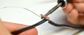
- The wire should be wound in one direction on each of the coils. This is necessary so that at the end the wires are located in the same direction and at the top there is a jumper between the taps connecting the coils, and at the bottom there is an input and an output.
- If you wind the wires incorrectly and they are located in different directions, then install a diagonal jumper between the upper and lower leads. The second pair of taps will play the role of input and output.
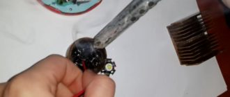
- It is recommended to install the choke in the welding machine only after the diodes. Connect the diode bridge cable to the input.
If the current strength of the choke, on the contrary, continues to fall during use, then you need to remove several turns on each of the coils.
Instead of a conclusion
Now you know how to make a choke for a welding machine with your own hands and use it in your work. You can easily assemble a homemade choke on your own, knowing the basic laws of electrical engineering. Tell us about your experience with throttle design in the comments and share this article on social networks. Good luck!
Source: https://svarkaed.ru/oborudovanie-dlya-svarki/detali-i-prisposobleniya/kak-sdelat-drossel-dlya-svarochnogo-apparata-postoyannogo-toka.html
How to make a choke for a welding machine with your own hands?
Almost every master has at least once thought about how to make a choke for a welding machine with his own hands.
Today, a fairly large number of different devices are sold that can be used in small-scale production.
This can be a device that operates on temporary or continuous current, a semi-automatic welding machine, or a product using electrodes. However, a high-quality device is very expensive, and budget analogues quickly become unusable.
Diagram of an AC welding machine with a separate choke: 1 – primary winding, 2 – core, 3 – secondary winding, 4 – choke winding, 5 – fixed part of the choke core, 6 – moving part of the choke core, 7 – screw pair, Dr – regulator current.
To assemble a homemade welding fixture, you will need to select and build all the necessary elements, including the throttle.
Benefits of using a throttle
Single-phase bridge rectification circuit (a). Graphs of voltage and current in the transformer (b), voltage and current in the load (c).
A welding choke is a device for regulating the current used to perform welding work. The element is needed to compensate for resistance that may be lacking. It can be connected to the re-winding of the transformer structure.
This makes it possible to shift the phases between the passing current and its voltage, as a result of which it is easier to ignite the electric arc at the beginning of work. It will burn evenly, and therefore it is possible to obtain a weld of good quality.
If you do not use the choke, problems may occur during welding.
The choke may consist of a semi-automatic design or a welding device that involves the use of electrodes. A semi-automatic machine with a throttle practically does not splash metal during operation. The welding process will be much smoother than without a choke.
The weld seam can be welded to a significant depth. The advantages of such an element are beyond doubt. It can be mounted not only on a homemade device, but also on a factory-made device. This is especially true for budget options that are prone to malfunctions.
This can significantly facilitate work on such structures and improve the quality of the weld.
What available tools can be used
Power supply diagram for an inverter welding machine.
To build a choke for welding with your own hands, the first step is to prepare the material. In this case, you can use almost any unused electrical devices.
The design is an ordinary core with a wound wire. For this purpose, you can use a transformer structure that was previously mounted in an old TV. The entire winding will need to be dismantled.
The core can be used to wind wire, the length of which is calculated in advance.
If possible, you can use parts that were installed in the lantern bulbs. Old windings should be dismantled, as they are often faulty. During the process of winding the wires, they will need to be installed in their original place.
To wind the inductor, you can use any core with a cross-section of approximately 12-15 cm. You will need to make a non-magnetic part between its elements. To do this, attach an insulation gasket approximately 0.6-1 mm thick.
Smooth current regulation can be achieved through the installation of movable windings of a transformer design. By changing the distance between the windings, you can change the magnitude of the magnetic flux and resistance in the repeat winding.
Current conversion in a welding inverter.
To weld with continuous current, an element must be connected to the winding at the output of the transformer structure to convert the temporary current into a continuous one. This device is called a rectifier. The current may not be continuous, but pulsating. It is possible to reduce ripple only by increasing the capacitance of the capacitor device.
To be able to adjust the arc current using a choke, 3 rectifiers must be connected between the output of the transformer structure and the point.
Elements that will be needed to construct the throttle:
- electrical design;
- wires;
- transformer;
- lantern lamp;
- cardboard for insulation.
How to make a choke for a welding device
Manufacturing diagram of a welding choke.
Before winding the wire, you will need to insulate the yoke. To wind the choke, you can use aluminum or copper wire. In the first case, its cross-section should be approximately 36-40 mm, in the second, the recommended cross-section is 25 mm. Instead of wire, you can use a copper busbar 4-5 mm thick. If you plan to use an aluminum part, it must be thicker.
The wire needs to be wound in an amount of 30-35 turns, the bus is wound in 3 layers. If an element from a lantern light bulb is used as the core, then winding should be done only on one side part along the entire length until the window is filled. The winding direction cannot be changed. Each layer must be isolated from the previous one.
It is recommended to impregnate the elements with bakelite varnish.
During the winding process, taps should be made through the same number of turns. The contacts must be strong, since they will bear a significant load.
Installing a throttle has a positive effect on the operation of a semi-automatic device or an ordinary homemade device. For a device that operates on temporary current, it is recommended to use a device together with a structure for rectifying the current. In this case, it will be possible to use almost all possible electrodes.
A do-it-yourself choke for welding can also be installed on a device with a step-down transformer design. The element must be connected to the secondary circuit of the transformer for welding.
This will make it possible to build a proprietary semi-automatic welding device, which is very expensive. The throttle should be accurately calculated according to the formula that is in the documentation supplied with the device.
This product will have a transformer design with good dissipation and excellent performance.
It is important to configure the choke for an inverter or any other device correctly.
Stepwise adjustment of the welding arc current can be achieved by switching on an ohmic resistance at the output, which is a nichrome spiral, through the same number of turns of which taps should be made with contacts that can withstand any load. The disadvantage of this method is that in this case the thread will become very hot.
When the welding choke setting is successful, you can begin welding work.
Existing methods for adjusting welding arc current
Scheme for welding thin metal using an inverter.
You can adjust the arc current by changing the air gap. The transformer device can be in the following modes:
- Idling. Temporary voltage is supplied to the input of the transformer device. In the repeat winding, an EMF is initiated, but there is no current in the output circuit.
- Load mode. In the process of igniting the arc, it will close the output circuit, which consists of re-winding the transformer device and the inductor winding. A current will flow, the value of which can be determined by the resistance of these windings. The degree of impact will depend solely on the size of the gap in the rod.
- Short circuit mode. The electrode touches the parts being connected. A temporary magnetic flux must be created in the core of the transformer structure. An emf should be initiated in the re-winding. The current in the circuit will be determined by the resistance value of the inductor and the winding of the transformer device.
The resistance will increase as the gap increases. This should lead to a decrease in magnetic flux. Eventually the arc current will increase. This method allows for smooth adjustment of the current, so it is recommended to use it.
The disadvantage of the moving system is that if the metal vibrates, the coil will become unreliable during the passage of temporary current. In this case, the adjustment can be made in steps. To do this, the choke should be made so that there is no gap in the wire.
It is not difficult to build a welding choke with your own hands. To do everything correctly, you will need to follow the technology, prepare all the necessary elements and follow the sequence of actions.
Source: https://masterinstrumenta.ru/svarka/drossel-dlya-svarochnogo-apparata-svoimi-rukami.html
Making a choke for a welding machine with your own hands
RUSENUKR
A step-down transformer is the basis of a simple welding machine. A more complex welding machine is one that has a rectifier at the output that converts alternating voltage into direct voltage. Such welding machines are called rectifiers.
There are three types of transformers: toroidal, rod and armored, the differences between them can be seen in the figure above.
The most complex is the welding machine, which first converts the input power frequency of 50 Hz into a direct voltage, like rectifiers, and then converts it into an alternating voltage, the frequency of which is measured in kilohertz. This is an inverter.
Only someone who is well versed in radio electronics and the element base used there can make an inverter with their own hands. For this specialist, there is no need to explain why the inductor is needed and where its place is in the circuit. It would be advisable to explain to an unprepared person what a transformer and a rectifier for it are.
Calculation of the cross-section of the wires of the primary winding of the transformer
Diagram of a welding transformer.
The theory of transformers is complex in that it is based on the laws of electromagnetic induction and other phenomena of magnetism. However, without using complex mathematical apparatus, it is possible to explain how a transformer works and whether it can be assembled independently.
The transformer can be manually wound on a metal core assembled from transformer steel plates. It is easier to wind on a rod or armored core than on a toroidal one. You should immediately note that the image clearly shows the difference in the thickness of the wires: the thin wire is located directly on the core, and a larger number of turns is clearly visible in it. This is the primary winding. The thicker wire with fewer turns is the secondary winding.
Without taking into account the power losses inside the transformer, let's calculate what the current I1 should be in its primary winding. The ideal network voltage is U=220 V. Knowing the power consumption, for example, P=5 kW, we have:
I1 = P:U= 5000:220=22.7 A.
Based on the current in the primary winding of the transformer, we determine the diameter of the wire. The current density for a household welding transformer should be no more than 5 A/mm2 of wire cross-section. Therefore, for the primary winding you will need a wire with a cross section of S1 = 22.7:5 = 4.54 mm2.
Using the cross-section of the wire, we determine the square, its diameter d without taking into account the insulation:
d2=4S/ =4 4.54/3.14=5.78.
Taking the square root, we get d=2.4 mm. These calculations were performed for copper wire cores. When winding wires with an aluminum core, the obtained result must be increased by 1.6-1.7 times.
For the primary winding, copper wire is used, the insulation of which must withstand high temperatures well. This is fiberglass or cotton insulation. Rubber and rubber-fabric insulation is suitable. Wires with PVC insulation should not be used.
Calculation of the cross-section of the wires of the secondary winding of the transformer
Diagram of a transformer with primary and secondary windings.
The voltage at the output of the welding machine transformer in the absence of a welding arc (idle mode) is usually 60-80 V. The higher the idle voltage, the more reliably the arc is ignited. The welding arc voltage is usually 1.8-2.5 times less than the no-load voltage.
Attention. It is necessary to constantly remember that in the absence of an arc the voltage at the transformer output is life-threatening.
For welding in everyday life, an electrode with a diameter of 3 mm is usually used, which is sufficient to provide an arc current of approximately 150 A. With an open circuit voltage of 70 V, the arc voltage will be approximately 25 V, and the power consumption P of the welding machine must be at least
Р=25 150=3750 W =3.75 kW.
It is advisable to design the transformer for higher power, that is, higher welding arc current. For example, with an arc current of 200 A, the power consumption will be approximately 5 kW. This is the power the transformer should be designed for.
The single-phase voltage in the house should be 220 V, but it can vary by ±22 V. This is one of the reasons why the arc current may change and will need to be adjusted.
The cross-section of the wire in the secondary winding of the transformer is determined based on the current density equal to 5 A/mm2. For a current of 200 A, the wire cross-section is 40 mm2, that is, it can only be a busbar that is wound with layer-by-layer insulation. Based on existing standard sizes, you can select the required tire both in length and cross-section.
Typical sizes of copper busbars produced by industry:
Manufacturing diagram of a welding choke
- length from 0.5 to 4 m with intervals of 0.5 m;
- width from 2 to 60 cm with intervals of 1 cm (with widths from 4 to 10 cm) and with intervals of 5 cm (with widths from 10 to 60 cm);
- thickness from 3 to 10 mm.
You can also use a stranded wire, the cross-section of which corresponds to the calculated value. To increase the cross-section, the wire can be folded in half or three. For aluminum wire, the cross-section must be increased by 1.6-1.7 times.
For a choke that is connected at the output of the transformer, the cross-section of the wire must be the same as in the secondary winding of the transformer.
Rectifier for welding machine
Electrical circuit of a welding machine rectifier.
To weld with direct current, an AC-to-DC converter must be connected to the output winding of the transformer. Such a device is called a rectifier, which is why a welding machine with this device is called a rectifier.
The top graph represents the sinusoidal voltage at the output of the transformer secondary winding. The horizontal t-axis is the time axis. The time interval between zero voltage values is determined by the oscillation period. It consists of positive and negative half-cycles.
It can be seen that the current is not constant, but pulsating. The only way to reduce ripple is by increasing the capacitance of the capacitor.
To regulate the arc current, the choke must be connected between the transformer output and point 3 of the rectifier.
Methods for regulating welding arc current
Let's consider one of the methods of regulating the welding arc current, based on the use of a choke in the secondary winding of the transformer. The arc current is regulated by changing the air gap provided in the core on which the busbar is wound.
Let's consider three modes in which a transformer can be.
Diagram of no-load and short circuit of a transformer.
- Idle mode. Alternating voltage is supplied to the input of the transformer. An emf is induced in the secondary winding, but there is no current in the output circuit.
- Load mode. As a result of ignition of the arc, it closes the output circuit, consisting of the secondary winding of the transformer and the inductor winding. A current flows, the magnitude of which is determined by the inductive reactance of these windings. If there were no choke, the current would be maximum. The degree of impact depends on the size of the air gap in the rod on which the winding is wound.
- Short circuit mode. This is the moment the electrode touches the parts of the workpiece being welded. An alternating magnetic flux is created in the transformer core, and an emf is induced in the secondary winding. The current in the circuit is determined by the inductive reactance of the inductor and the secondary winding of the transformer.
As the gap increases, the resistance increases. This leads to a decrease in the magnetic flux and, accordingly, to a decrease in the inductive resistance of the choke coil and the total resistance of the circuit. The arc current increases. This method allows you to smoothly regulate the current.
Transformer assembly diagram.
However, the moving system has the disadvantage that as a result of the vibration of the metal when passing alternating current through the coil, it becomes not very reliable.
You can, sacrificing the smoothness of the adjustment, make it stepwise. To do this, it is necessary to make the choke so that there is no air gap in the magnetic core. During the winding process, taps must be made through a certain number of turns. In this option, the current can be adjusted in steps, through contacts that must be made powerful in order to carry a current of hundreds of amperes.
There is another reason why the throttle must be turned on to create normal manual welding conditions.
The characteristic of the dependence of arc voltage on its current is called falling. An inexperienced welder will have to believe that such a relationship is useful when welding if it is difficult to maintain a constant distance between the electrode and the parts being welded. To provide such a characteristic, the inductive reactance of the secondary winding of the transformer alone is not enough. The immediate task of a choke for a welding machine is to add the missing resistance.
How to make a choke and wind it correctly?
To wind the choke coil, you can use a UI series magnetic core. Table 1 shows the dimensions corresponding to the maximum values of parameters a and b.
Table 1.
| Name | a, mm | b, mm | c, mm | d, mm | e, mm | f, mm | h, mm | i, mm | k1, mm | k2, mm | Holes, mm |
| UI 90 | 90 | 120 | 90 | 30 | 30 | 30 | 7,8 | 60 | 15 | 105 | 4 |
| UI 120 | 120 | 160 | 120 | 40 | 40 | 40 | 11,0 | 80 | 20 | 140 | 4 |
Before winding, it is necessary to insulate the yoke. During the winding process, its direction does not change. The next layer is isolated from the previous one with cotton insulation. You can use fiberglass or cardboard designed for insulation. The insulating gasket is impregnated with bakelite varnish. If conclusions are drawn during winding, they should be marked immediately.
The welding arc current can be adjusted stepwise by turning on a load ohmic resistance at the output in the form of a nichrome spiral, with periodic taps. However, this method is inconvenient due to the possible high heating of the filament (even red hot).
For smooth adjustment, movable windings of the transformer are created. By changing the distance between the primary and secondary windings, they change the magnitude of the magnetic flux and, consequently, the resistance in the secondary winding of the transformer.
But for a welding machine used in everyday life, the most suitable method is a smooth adjustment using a throttle.
Source: https://stroystory.ru/kovka/instrumenty-6/6515-izgotovlenie-drosselja-dlja-svarochnogo-apparata.html
How to wind a choke for a welding machine - Metalworker's Guide
Almost every master has at least once thought about how to make a choke for a welding machine with his own hands.
Today, a fairly large number of different devices are sold that can be used in small-scale production.
This can be a device that operates on temporary or continuous current, a semi-automatic welding machine, or a product using electrodes. However, a high-quality device is very expensive, and budget analogues quickly become unusable.
Diagram of an AC welding machine with a separate choke: 1 – primary winding, 2 – core, 3 – secondary winding, 4 – choke winding, 5 – fixed part of the choke core, 6 – moving part of the choke core, 7 – screw pair, Dr – regulator current.
To assemble a homemade welding fixture, you will need to select and build all the necessary elements, including the throttle.
Choke for a welding machine: why you need it and how to assemble it yourself (instructions and diagram)
Recently, electric welding has become extremely popular in the professional sphere and at home, but we all know how many problems welders face.
The current market segment of electrical engineering offers a lot of machines for welding using an electric arc, starting from small and not very powerful welders for the home and performing small volumes and tasks, and right up to huge industrial machines with high productivity, which are sent directly from shops to huge factories.
But such a problem as sudden, and most importantly uncontrollable voltage drops, is known to professionals and home craftsmen.
These problems cannot be affected by overly expensive equipment or the type of application, this is a typical welder’s scourge, such little things drive even experienced craftsmen crazy, and a beginner will simply turn away forever from working with welding that does not cope with its functions. This phenomenon affects the arc and seam formation becomes more difficult.
But such a problem is in the past, because there is such an innovation as a choke, it makes the cooking process much easier, and most importantly, makes it safer in many ways.
It is introduced into the welding process chain, and welding is ready for comfortable operation. Beginners, of course, are not aware of current, what a choke is and how it is useful, how it works, how to make it at home. This article will shed light on all your questions and more.
General statements
So why do we need a choke on a welding machine? Perhaps we can do without it? Yes, of course you can, but for effective and comfortable welding it is simply necessary.
This is a small element that is connected to the circuit, and it provides stable, uninterrupted, smooth heating of the arc.
At the second stage, it maintains this stable state, and the metal does not fly away in all directions, which often happens and, incidentally, can lead to severe burns.
During operation, the seam comes out neat, the machine is adjusted more accurately and can even weld difficult elements, but of course, a lot also depends on the professionalism of the master in whose hands the welding fell.
The principle of the robot is easy and understandable to everyone: the inductor passes current through itself, keeping it away from the welding machine.
And then this stored current replenishes those same voltage surges, which allows welding to work stably. Another choke with magnetization allows you to provide the necessary resistance if the voltage suddenly goes up.
Buying a choke for a welding machine in stores is not a cheap pleasure, yes, of course, you can look for something more budget-friendly, but will it work well?
You can do it at home yourself, for this you will need very little logic, time, and inexpensive materials that you probably have lying around in the garage.
The inductor design is a core with two coils with a cross-section designed for use with a constant current value.
So, unfortunately, we can’t make a choke that would be suitable for different welding machines, it’s a pity, but it’s a fact. A small part will obviously not be able to handle a strong welder.
So it is advisable to know in advance the number of skeins, which will be useful for working with different voltages.
Using the throttle
Welding transformers are the best basis for creating a choke at home. This has been proven in practice more than once.
It easily, but smoothly heats our arc, at any current, so it is suitable for ordinary summer residents, as well as for working in factories and concerns with voltage surges.
You can also take a choke for a welding machine along with a rectifier. A pair of inductor and rectifier has the ability to increase the electromotive force of self-induction.
For example, if we are talking about semi-automatic devices, then this pair can strike an arc even at a large distance from the metal.
Homemade choke
So let's start building a choke for a welding machine at home; for this we will need to know how to wind a coil. In order to do everything in the best possible way, quickly and efficiently, we must have a good understanding of how the throttle works.
You learned everything you need about the functions and design of the throttle from the previous sections, of course, if you were careful.
We have also written a small instruction for you, using which you will definitely be able to build a wonderful device. Let's start our simple work on a very useful device:
- First of all, let's find an old transformer; it will serve as an excellent base for us. Experts in this matter advise using parts from TCA 270-1 televisions; it should become our core. Such little things are always not difficult to find in spontaneous markets, or you were lucky and your grandmother had a TV of the right model lying around, but if not, then the Internet will certainly not deny you an abundance of junk.
- Next, we must obtain the necessary parts from the transformer; for this we must get rid of the fasteners, often they are on top and, of course, get our coil.
- Next, you must form gaskets for the induction passage that will be glued to the previously mined element.
- Now a difficult and painstaking stage awaits us, but the result of our entire work greatly depends on it; we must wind the wire. We need a wire, preferably made of aluminum, with a cross-section of at least 36 millimeters. Next we apply 25-26 turns on each side. If you have found all the parts we recommend, then everything should come out very clearly and neatly. The insulation between the turns is also very important; you can make it with paper, and of course varnish it with insulating lubricants.
- Wind the cord in one direction on both coils, otherwise there is a risk that at the end the cords will point in different directions, jumpers will not appear between the taps that connect the coils, and the input and output will not be positioned correctly.
- But if it already happens that you wound so that the wires point in different directions, it’s not a problem - we need to attach a diagonal jumper between the upper and lower taps. Here the second pair will serve as the entrance and exit.
- It is recommended to integrate a choke into the welding after the diodes.
But if even after all our manipulations the voltage jumps, then you just need to remove a couple of turns from the coil.
Bottom line
Congratulations, if you have mastered all our tips, then you will certainly be able to make a choke for a welding machine with your own hands. It was not difficult at all, it took a little perseverance and technical savvy.
But at the end you will receive a high-quality device (of course, if you did everything correctly), of course you will be proud that it was made by yourself, and you can even teach it to one of your friends or relatives.
Tell us about how you made your throttle, what problems arose, what the result was, show the article to your friends. Peace and new heights to everyone!
Source: https://prosvarku.info/prisposobleniya-i-detali/drossel-dlya-svarochnogo-apparata-svoimi-rukami