DIY welding machine from a transformer
Equipment for welding work does not have to be purchased in a store. It can be made in a home workshop. After all, in fact, the design of the simplest device is elementary and assembling a welding machine with your own hands is not difficult. To do this, you only need some components and a little knowledge of electrical engineering.
How to make simple and, at the same time, functional machines for welding work and what is required for this - more on this later in our article.
What is needed for welding assembly
To assemble a simple welding machine, you need to understand the principle of its operation.
All welding work is based on the conversion of electrical current from the network. For domestic use, we have access to electricity with a voltage of 220 volts and a current of 16-32 amperes.
As we know, this is not enough for welding.
A welding arc requires power, and it is provided by current, measured in amperes (in simple terms, this is the number of electrons supplied to the electrode). The more charge, the more productive the device will be.
To increase power, transformers are used that lower the voltage several times, but increase the flow of electrons, which allows the use of such current to form a welding arc.
A transformer is the main element that allows you to assemble a simple device that runs on alternating current.
The basis of the transformer is a magnetic core (core made of transformer steel), on which windings are wound: the primary, made of thinner wire and a large number of turns. and a secondary one, consisting of a thick cable with the least number of windings.
Magnetic cores for assembling welding machines can be used, for example, from old power transformers.
Power is provided from a household outlet and applied to the primary winding.
The windings should not be in contact with each other. Even if the transformer has windings one on top of the other, there must be a layer of insulation between them! Current from one winding to another is transmitted through the core by magnetic flux.
As welding cables, you can use factory-made products, or select a wire with a suitable cross-section. The main thing is that they must withstand the power of the device.
The holders are made from rods or reinforcement of small diameter. In shape they resemble a three-pronged fork, into the teeth of which the electrode is fixed.
How to assemble transformer welding
To do this, you need to find a working step-down transformer. You can take models S-B22, IV-10, or IV-8, the power of which should be 1-2 kW. Such elements are typically used to power various power tools and reduce the voltage from 220 to 36 volts.
Transformer welding is assembled according to the following algorithm.
- Initially, you need to remove the secondary winding from the transformer, but you must not damage the primary.
- The removed wire is wound onto the primary coil, which is located in the middle of the core. At the same time, for every 30 skeins, a layer is created (8-10 pieces are needed), which are numbered for convenience.
- The other two sides of the core are wrapped with a cable with several cores (at least three copper wires with a cross-section of 6-8mm). Each coil will require up to 12 meters of such wire. This will be the secondary winding of the device (VO).
- The terminals are made of a copper tube with a diameter of 10-12 mm, while the cable is inserted into one end and clamped, the other edge is flattened and a hole is drilled for fastening. The VO cables are attached to this clamp.
- On the transformer, the M6 fastener must be replaced with a more powerful one (located on the top panel). The secondary winding cable is connected to this mount.
- For the primary winding you will need a piece of textolite board with ten holes, in each of which an M6 mount is mounted.
- To ensure operation, you need to connect the primary winding in series from the outer coils, and then from the middle coil. Taps from the secondary winding are inserted into the board holes numbered 1 to 10. The current will be regulated by the terminals.
- The electrode holder can be made from a 5 mm steel bar to which the cable is attached. It is made in the form of a three-pronged fork. A piece of rubber hose is put on the handle.
- You can attach a magnet holder to the mass cable, or you can make a steel hook that can be attached to workpieces.
In such a device, the current in the primary winding will be 25 Amperes, and in the secondary - 60-120 A. Power is provided through a household outlet. The power of the device will ensure excellent operation of electrodes with a diameter of 2 mm. For a triple consumable, the welding time will be limited (non-stop up to 10-15 electrodes, then you need to let the transformer cool).
If you have little experience in electrical engineering, then you need to study in more detail the materials on how to create such a device.
Microwave spot welding
Spot welding allows you to join very thin metal where traditional welding machines would simply burn the part.
The simplest homemade spot welding machine can be assembled with a minimum amount of materials, using an old working microwave, from which you will need to remove a transformer with a power of 1 kW or more. One such element will be enough to weld metal up to 1 mm thick in spots. To increase power, two transformers can be used.
In a microwave, most of the work is done by the magnetron, which requires about 4,000 volts of power. For this purpose, the transformer works not to lower, but to increase the voltage. At the output, such an element gives up to 2000 V.
Source: https://MyTooling.ru/instrumenty/svarochnyj-apparat-svoimi-rukami-iz-transformatora
DIY DC welding machine: my diagram
20 years ago, at the request of a friend, I built him a reliable welder to work on a 220-volt network. Before this, he had problems with his neighbors due to a voltage drop: an economical mode with current regulation was required.
After studying the topic in reference books and discussing the issue with colleagues, I prepared an electrical control circuit using thyristors and installed it.
In this article, based on personal experience, I tell you how I assembled and configured a DC welding machine with my own hands based on a homemade toroidal transformer. It came out in the form of a small instruction.
I still have the diagram and working sketches, but I can’t provide photographs: there were no digital devices then, and my friend moved.
Versatile capabilities and tasks performed
A friend needed a machine for welding and cutting pipes, angles, sheets of different thicknesses with the ability to work with 3÷5 mm electrodes. Welding inverters were not known at that time.
We settled on the DC design, as it is more universal and provides high-quality seams.
Thyristors removed the negative half-wave, creating a pulsating current, but did not smooth out the peaks to an ideal state.
The welding output current control circuit allows you to adjust its value from small values for welding up to 160-200 amperes required when cutting with electrodes. She:
- made on a board from thick getinax;
- covered with a dielectric casing;
- mounted on the housing with the output of the adjusting potentiometer handle.
The weight and dimensions of the welding machine were smaller compared to the factory model. We placed it on a small cart with wheels. To change jobs, one person rolled it freely without much effort.
The power cord was connected through an extension cord to the connector of the input electrical panel, and the welding hoses were simply wound around the body.
Simple design of DC welding machine
Based on the installation principle, the following parts can be distinguished:
- homemade transformer for welding;
- its power supply circuit is from network 220;
- output welding hoses;
- power unit of a thyristor current regulator with an electronic control circuit from a pulse winding.
Pulse winding III is located in power zone II and is connected through capacitor C. The amplitude and duration of the pulses depend on the ratio of the number of turns in the capacitor.
How to make the most convenient transformer for welding: practical tips
Theoretically, you can use any model of transformer to power the welding machine. The main requirements for it:
- provide arc ignition voltage at idle speed;
- reliably withstand the load current during welding without overheating the insulation from prolonged operation;
- meet electrical safety requirements.
In practice, I have come across different designs of homemade or factory-made transformers. However, they all require electrical engineering calculations.
I have been using a simplified technique for a long time, which allows me to create fairly reliable transformer designs of medium accuracy class. This is quite enough for household purposes and power supplies for amateur radio devices.
It is described on my website in an article about making a transformer soldering iron Moment with your own hands. This is an average technology. It does not require clarification of the grades and characteristics of electrical steel. We usually don’t know them and cannot take them into account.
Features of core manufacturing
Craftsmen make magnetic wires from electrical steel of various profiles: rectangular, toroidal, double rectangular. They even wind coils of wire around the stators of burnt-out powerful asynchronous electric motors.
We had the opportunity to use decommissioned high-voltage equipment with dismantled current and voltage transformers. They took strips of electrical steel from them and made two donut rings out of them. The cross-sectional area of each was calculated to be 47.3 cm2.
They were insulated with varnished cloth and secured with cotton tape, forming a figure of a reclining figure eight.
They began to wind the wire on top of the reinforced insulating layer.
Secrets of the power winding device
The wire for any circuit must have good, durable insulation, designed to withstand long-term operation when heated. Otherwise, it will simply burn during welding. We proceeded from what was at hand.
We received a wire with varnish insulation, covered with a fabric sheath on top. Its diameter - 1.71 mm is small, but the metal is copper.
Since there was simply no other wire, they began to make the power winding out of it with two parallel lines: W1 and W'1 with the same number of turns - 210.
The core donuts were mounted tightly: this way they have smaller dimensions and weight. However, the flow area for the winding wire is also limited. Installation is difficult. Therefore, each power half-winding was separated into its own magnetic circuit rings.
In this way we:
- doubled the cross-section of the power winding wire;
- saved space inside the donuts to accommodate the power winding.
Wire alignment
You can get a tight winding only from a well-aligned core. When we removed the wire from the old transformer, it turned out to be bent.
We figured out the required length in our minds. Of course it wasn't enough. Each winding had to be made from two parts and spliced with a screw clamp directly on the donut.
The wire was stretched along its entire length on the street. We picked up the pliers. They clamped the opposite ends and pulled with force in different directions. The vein turned out to be well aligned. They twisted it into a ring with a diameter of about a meter.
Technology of winding wire on a torus
For the power winding, we used the rim or wheel winding method, when a large-diameter ring is made of wire and wound inside the torus by rotating one turn at a time.
The same principle is used when putting a winding ring on, for example, a key or keychain. After the wheel is inserted inside the donut, they begin to gradually unwind it, laying and fixing the wire.
This process was well demonstrated by Alexey Molodetsky in his video “Winding a torus on a rim.”
This work is difficult, painstaking, and requires perseverance and attention. The wire must be laid tightly, counted, the process of filling the internal cavity must be monitored, and the number of turns wound must be recorded.
How to wind a power winding
For it, we found a copper wire of a suitable cross-section - 21 mm2. We estimated the length. It affects the number of turns, and the no-load voltage necessary for good ignition of the electric arc depends on them.
Typically reference books recommend 60-70 volts. One experienced welder told us that in our case 50 would be enough. We decided to check it, and if it wasn’t enough, then increase the winding further.
We made 48 turns with the middle terminal. In total, there were three ends on the donut:
- middle - for direct connection of the “plus” to the welding electrode;
- the outer ones - to the thyristors and after them to ground.
Since the donuts are fastened together and the power windings are already mounted on them along the edges of the rings, the winding of the power circuit was carried out using the “shuttle” method. The aligned wire was folded like a snake and pushed through the holes of the donuts for each turn.
The middle point was unsoldered using a screw connection and insulated with varnished cloth.
Reliable welding current control circuit
The work involves three blocks:
- stabilized voltage;
- formation of high-frequency pulses;
- separation of pulses into circuits of thyristor control electrodes.
Voltage stabilization
An additional transformer with an output voltage of about 30 V is connected from the power winding of the 220 volt transformer. It is rectified by a diode bridge based on D226D and stabilized by two zener diodes D814V.
In principle, any power supply with similar electrical characteristics of current and output voltage can work here.
Pulse block
The stabilized voltage is smoothed by capacitor C1 and supplied to the pulse transformer through two bipolar transistors of direct and reverse polarity KT315 and KT203A.
Transistors generate pulses to the primary winding Tr2. This is a toroidal type pulse transformer. It is made of permalloy, although a ferrite ring can also be used.
Winding of three windings was carried out simultaneously with three pieces of wire with a diameter of 0.2 mm. Made 50 turns. The polarity of their inclusion matters. It is shown by dots in the diagram. The voltage on each output circuit is about 4 volts.
Windings II and III are included in the control circuit for power thyristors VS1, VS2. Their current is limited by resistors R7 and R8, and part of the harmonic is cut off by diodes VD7, VD8. We checked the appearance of the pulses with an oscilloscope.
In this chain, the resistors must be selected for the voltage of the pulse generator so that its current reliably controls the operation of each thyristor.
The unlocking current is 200 mA, and the unlocking voltage is 3.5 volts.
Welding current regulation
Variable resistor R2, with its resistance, determines the position of each pulse passed through the control electrode of the thyristor. The shape of the pulsating current at the output of the power circuit of the welding machine depends on it.
Half-sine ripples can pass through completely when the welding current is set to maximum or be cut off to almost zero.
Personal impressions of use
When the DC welding machine was made with our own hands, we began to study its capabilities. First of all, we experimented with the polarity of the electrode connection and identified a pattern.
The electrode can be supplied with “plus” - direct polarity or “minus” - reverse polarity. In this case, the depth of weld penetration changes. With reverse polarity it increases by about 40-50%.
Our welding machine allows you to weld with 3 mm electrodes, providing a welding current of 80 amperes for quite a long time. The heating of the structure does not exceed operating conditions. At the same time, the load in the household wiring network is maintained at a level of up to 20 A.
If there is a need to use 4 mm electrodes or increase the welding current, then it is necessary to organize breaks in work to cool the machine. Ours is natural: due to cracks and holes.
The cooling system can be enhanced by forced ventilation by blowing. But we did not deal with this issue.
I show the scanned handwritten text of a preserved document. It may be useful for repetition.
And now I recommend watching the video by the owner of zxDTCxz “Welding machine based on a toroidal magnetic core.” It contains many useful recommendations.
If you still have questions on the topic, then ask them in the comments, I will answer.
Source: https://HouseDiz.ru/svarochnyj-apparat-postoyannogo-toka-svoimi-rukami-moya-sxema/
Homemade welding transformer
Today it is difficult to imagine the manufacture of various types of metal structures without the use of welding equipment. High performance, ease of operation, and reliability of the resulting connections have allowed DIY welding transformers to take their own place in the list of basic construction tools. You can buy such a device today at any construction equipment store.
Transformer operating principle
To perform electric welding, special portable devices have been developed that are lightweight and fairly compact in size. To connect copper wires, a constant current of straight polarity is used.
This indicates that the electrode holder is set to “plus”, and the grounding device is set to “minus”. For some types of copper-clad electrodes, reverse polarity current may be used.
The current parameters are regulated by a special mechanism.
On different welding devices, the arc current may be limited or there may be an output voltage regulator.
Quite often, when mentioning the concept of “transformer for welding,” they mean devices equipped with a current control mechanism and the presence of a constant output voltage. This definition is not correct enough, because a step-down transformer, which is used for welding equipment, can only reduce the voltage.
Selection of welding voltage| Voltage, V | 10 | 12 | 20 | 25 | 30 | Wire diameter, mm | 0,05-0,1 | 0,1-0,3 | 0,3-0,5 | 0,5-1,0 | 1,0-2,0 |
The current is rectified by a ripple filter, a diode bridge, and a special regulator is provided.
Selection of welding current| Welding current, A | 70 | 80 | 100 | 120 | Number of wires, pcs. | 2 | 3 | 2 | 4 | Wire cross-section, mm2 | 1,5 | 1,5 | 2,5 | 2,5 |
Thanks to their vast experience, electric welders using only one transformer are able to weld wires without an AC regulator, holding the arc for the required amount of time. This welding option gives the worst result; To obtain a high-quality connection, you need to have considerable skill.
Therefore, this connection option is not recommended for beginners. In order to master electric welding technology, you should first buy a good factory welding machine.
Do-it-yourself contact welding from a microwave
To make a welding transformer with your own hands at home, you will need the following tools and materials:
- base for mounting structural elements of the welding machine;
- based on the required power of the unit, you will need one or two transformers from an old microwave;
- large-section copper wire or a bunch of small-section wires;
- one lever of a certain length;
- clamping levers;
- clamping clamps;
- cables, winding materials;
- screwdriver set;
- copper electrodes.
Recommendations
- In order for a home-made device to connect sheet iron less than 1 mm thick, the transformer must have a power of at least 1 kW. When using two transformers in the design, the power of the unit will be correspondingly much greater.
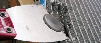
- To independently make such a tool for resistance welding, you do not need the entire transformer from a microwave oven, but only its individual elements - the primary winding, the magnetic wire. The shunts and secondary winding are removed from the transformer.
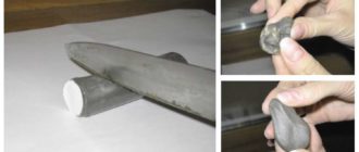
- For a new winding (2-3 turns will be enough), a stranded wire is used, the diameter of which should be at least 1 cm. If the insulating layer on the wire is thick enough, it can be carefully removed and the wire insulated with a special fabric tape.
- When two transformers are used simultaneously, the secondary winding is made common.
The final stage of assembling a tool for welding copper wires is the installation of control mechanisms, connecting electrodes, combining all structural elements in a single housing, which is also taken from old, non-working household appliances.
Source: https://electrod.biz/oborudovanie/samodelnyiy-svarochnyiy-transformator.html
What you need to know to assemble a welding machine with your own hands
Anyone familiar with the rules of electrical installation can easily make a simple welding machine on their own. But before getting down to business, it is necessary to calculate all the components of the device. The efficiency of the device when operating from a regular household single-phase network will depend on this.
Design and principle of operation of the simplest welding machines
To obtain a stable welding arc, which will allow you to weld metal of different thicknesses, currents in the range of 70 - 150 A are required. If you use devices designed for a voltage of 220 V, then they must consume high power, in the range of 15 - 30 kW. Therefore, such installations will be cumbersome, and it will not be possible to work with them normally. But at home it will simply be impossible to connect them; standard networks are not designed for such a load.
Therefore, the main task in the design and assembly of welding machines is to provide the required current while reducing power consumption. This is only possible when performing welding work with reduced voltage on the electrodes.
The simplest welding machine has the following design:
- A step-down transformer that reduces the voltage to the limits of 55 - 70 V and at the same time increases the current strength to the required parameters. Thanks to this, it is possible to reduce energy consumption to reasonable limits.
- Current is supplied from the transformer to the electrode and the workpiece using special welding cables. They are distinguished by a larger cross-section and reinforced insulation, allowing them to work with high currents.
- For welding, you will need electrodes installed in the holder. Thanks to the coating used, they simplify the ignition and maintenance of the electric arc, which becomes the source of thermal energy necessary for melting the metal.
Welding transformer
There are no complex devices in the design of such welding machines. But during design, it is necessary to calculate the basic parameters, otherwise connecting inappropriate equipment to the network will lead to its failure, short circuits on the line, or it will simply be impossible for them to cook.
Types of welding machines
There are several main types:
Welding transformer. A step-down transformer is used for the converter.
Welding transformer
Welding inverter. An inverter power supply with PWM serves as a converter here.
Welding rectifier. This is the same as a welding transformer, only it has a diode or thyristor rectifier in the secondary circuit.
Welding rectifier
Semi-automatic Welding is carried out in an inert environment; a gas cylinder is used for this.
Also read: How to make a phase indicator with your own hands
Simplified welder calculation diagram
In practice, calculations are made based on the type and diameter of the electrodes used. Yes, there are more complex and accurate calculation formulas, but they are rarely used by amateurs. To obtain a stable and productive arc, it is necessary to obtain a current with the following indicators:
- For electrodes with a diameter of 2 mm, 30 - 80 A is sufficient.
- When the diameter increases to 3 mm, the current should increase to 70 - 130 A.
- For 4 mm electrodes, the value is set to 110 - 170 A.
- 5-mm electrodes are cooked at a current of 150 - 200 A.
The difference in current values is due to working with metals of different thicknesses and physical properties.
When making a welding machine yourself, you most often have to be content with a magnetic core from other devices, which is available. Therefore, the simplest calculation will be performed based on these two known characteristics - the cross-section of the magnetic circuit and the required current strength on the secondary winding.
Please note that it is preferable to use rod-type cores to assemble the transformer. Compared to armored ones, they provide a higher current density in the windings and have increased efficiency.
Types of magnetic cores
In addition, the location of the windings on the arms of the core is also important. If the primary and secondary windings are separated into different rods, this will lead to increased magnetic dissipation due to the increased air gap. Therefore, it is considered preferable to place a part of both windings on both one and the other rod.
In this case, to determine the required number of turns of the primary winding, use the following formula:
N1 = 7440 × U1/(Sout × I2)
Where
N1 - estimated number of turns;
U1 - mains voltage (200-240V);
Source: https://OFaze.ru/svoimi-rukami/svarochnyj-apparat
Instructions for assembling a welding machine with your own hands
A welding machine is highly specialized equipment, but almost every man has had to look for a similar unit more than once in his life to repair home appliances or a car. It is quite easy to make a welding machine with your own hands, but you should understand that the equipment is suitable for working on small structures. This will be electric arc welding from an AC or DC source.
Argon and gas welding require special knowledge and equipment. You can make a gas generator at home, but if the master does not have a specialized education, there is a high risk of making a mistake. It is easier to rent an argon-arc welding machine; it costs tens of times less than making the equipment yourself.
Block diagram of the welding machine
A welding machine for home use is a simplified design with the simplest components and a simple assembly diagram. The main part is a welding transformer, which you can make yourself or use a component from a household appliance (for example, a microwave oven).
The inverter welding unit is designed according to the following diagram:
- power supply;
- rectifier;
- inverter
You can make a transformer yourself using waste wire cables and copper tape of the required length.
If the transformer uses round copper wire, the operation of the device is limited to 2-3 welding rods. Transformer oil is used for cooling.
The seam on the parts being connected is formed due to heat, the source of which is an electric arc that occurs between two electrodes. One of the electrodes is the material being welded.
A short circuit, which is required to heat up the electrode (cathode), will lead to a stable discharge with a temperature of up to 6000°C. Under its influence, the metal will begin to melt.
This is a rough description of the welding process for non-specialists who, in everyday life, simply need to quickly fix the required profile or part.
Product contents
Welding inverters are rarely made independently. This electronic device requires repeated testing, specific knowledge and experience. It is easier to make a homemade product based on a transformer, and since it must work from a household network (usually 220 V), this device will be quite sufficient for minor home repairs.
A welding inverter for a 220 V network is assembled according to a circuit that is used for devices operating from an industrial three-phase network. You need to know that these devices will have an efficiency 60% higher than equipment adapted for a single-phase network.
The transformer welder is manufactured without additional components, the package includes:
- transformer (you can make it yourself);
- insulating material;
- welding rod holder;
- PRG cable.
More complex inverter products are equipped with:
- transformer;
- inverter;
- ventilation system;
- ampere regulator.
After assembly, the voltage of the secondary winding is measured: the values should not exceed the parameters of 60-65 V.
Power supply for a simple welder
Homemade welding transformers are simple equipment for rare repairs. The stator can serve as a magnetic core. The primary winding will be connected to the network, the secondary winding is designed to receive an electric arc and perform work. The transformer winding consists of copper wire or tape (up to 30 meters).
Source: https://InfoKuzov.ru/material-instrument/svarochnij-apparat-svoimi-rukami
2 options for assembling a simple welding machine
Nowadays, it is difficult to imagine any work with metal without the use of a welding machine. Using this device, you can easily connect or cut iron of various thicknesses and dimensions. Naturally, to perform high-quality work you will need certain skills in this matter, but first of all you need the welder itself.
Nowadays, of course, you can buy it, as well as, in principle, hire a welder, but in this article we will talk about how to make a welding machine with your own hands. Moreover, with all the wealth of different models, reliable ones are quite expensive, and cheap ones do not shine with quality and durability.
But even if you decide to buy a welder in a store, reading this article will help you choose the necessary device, since you will know the basics of their circuitry. There are several types of welders: direct current, alternating current, three-phase and inverter.
In order to determine which option you need, we will consider the design and device of the first two types, which you can assemble with your own hands at home without any specific skills.
AC
This type of welding machine is one of the most common options, both in industry and in private households.
It is easy to use and, compared to others, can be made quite easily at home, as evidenced by the photo below.
To do this, you need to have a wire for the primary and secondary windings, as well as a transformer steel core for winding the welder. In simple words, an AC welding machine is a high-power step-down transformer.
The optimal voltage when operating a welding machine assembled at home is 60V. The optimal current is 120-160A. Now it’s easy to calculate what cross-section the wire should have in order to make the primary winding of the transformer (the one that will be connected to the 220 V network). The minimum cross-sectional area of the copper wire should be 3-4 square meters. mm, the optimal is 7 sq.
mm, because it is necessary to take into account voltage drops and possible additional load, as well as the necessary safety margin. We find that the optimal diameter of the copper core for the primary winding of a step-down transformer should be 3 mm.
If you decide to take an aluminum wire to make a welding machine with your own hands, then the cross-section for the copper wire must be multiplied by a factor of 1.6.
It is important that the wires are covered in rag braid; conductors in PVC insulation cannot be used - when the wires heat up, it will melt and a short circuit will occur. If you do not have a wire of the required diameter, you can use thinner wires, winding them in parallel.
But then it should be taken into account that the thickness of the winding will increase, and, accordingly, the dimensions of the device itself. It must be borne in mind that the limiting factor may be a free window in the core and the wire may simply not fit there. For the secondary winding, you can use a thick stranded copper wire - the same as the core on the holder.
Its cross-section should be selected based on the current in the secondary winding (remember that we are focusing on 120 - 160A) and the length of the wires.
The first step is to make a transformer core for a homemade welding machine. The best option would be a rod-type core as shown in Figure 1:
This core must be made from transformer steel plates. The thickness of the plates should be from 0.35 mm to 0.55 mm. This is necessary to reduce Foucault currents. Before assembling the core, you need to calculate its dimensions, this is done as follows:
- First, the window size is calculated. Those. Dimensions c and d in Figure 1 must be chosen such as to accommodate all the windings of the transformer.
- Secondly, the roll area, which is calculated by the formula: Roll = a*b, must be at least 35 square meters. cm. If there is more Skren, then the transformer will heat up less and, accordingly, work longer, and you will not need to interrupt often in order for it to cool down. It is better that the Skrena is equal to 50 square meters. cm.
Next, we proceed to assembling the plates of a homemade welding machine. It is necessary to take the L-shaped plates and fold them, as shown in Figure 2, until you can make a core of the required thickness. Then we fasten it with bolts at the corners. Finally, it is necessary to process the surface of the plates with a file and insulate them by wrapping them with rag insulation in order to further protect the transformer from breakdown to the housing.
Next, we proceed to winding the welding machine from the step-down transformer. First, we wind the primary winding, which will consist of 215 turns, as shown in Figure 3.
It is advisable to make a branch from 165 and 190 turns. We attach a thick textolite plate to the top of the transformer.
We fix the ends of the windings on it using a bolted connection, noting that the first bolt is a common wire, the second is a branch from the 165th turn, the 3rd is a branch from the 190th turn and the 4th is from the 215th.
This will make it possible to subsequently regulate the current during welding by switching between different terminals of your welding device. This is a very important function, and the more branches you make, the more precise your adjustment will be.
Then we proceed to winding 70 turns of the secondary winding, as shown in Figure 4.
A smaller number of turns are wound on the other side of the core - where the primary winding is wound. The ratio of turns should be approximately 60% to 40%. This ensures that after you catch the arc and start welding, the eddy currents will partially turn off the operation of the winding with a large number of turns, which will lead to a decrease in the welding current, and accordingly improve the quality of the seam.
This way the arc will be easy to catch, but too much current will not interfere with quality welding. We will also secure the ends of the winding with bolts to the textolite plate. You can not attach them, but run the wires directly to the electrode holder and the crocodile to ground; this will remove connections where there could potentially be a voltage drop and heating.
For better cooling, it is highly advisable to install a fan for blowing, for example from a refrigerator or microwave.
Now your homemade welding machine is ready. Having connected the holder and ground to the secondary winding, it is necessary to connect the network to the common wire and the wire extending from the 215th turn of the primary winding.
If you need to increase the current, you can make fewer turns of the primary winding by switching the second wire to a contact with fewer turns. The current can be reduced using a resistance made from a piece of transformer steel bent into a spring and connected to a holder.
It is always necessary to ensure that the welding machine does not overheat; to do this, regularly check the temperature of the core and windings. For these purposes, you can even install an electronic thermometer.
This is how you can make a welding machine from a step-down transformer with your own hands. As you can see, the instructions are not too complicated and even an inexperienced electrician can assemble the device on their own.
DC
Some types of welding require a DC welder. This tool can be used to weld cast iron and stainless steel. You can make a DC welding machine with your own hands in no more than 15 minutes by remaking a homemade product using alternating current. To do this, you need to connect a rectifier assembled with diodes to the secondary winding. As for the diodes, they must withstand a current of 200 A and have good cooling. D161 diodes are suitable for this.
Capacitors C1 and C2 with the following characteristics will help us equalize the current: capacitance 15000 μF and voltage 50V. Next, we assemble the circuit shown in the drawing below. Inductor L1 is needed to regulate the current. Contacts x4 are plus for connecting the holder, and x5 are minus for supplying current to the part to be welded.
Three-phase welding machines are used for welding in industrial conditions, they are equipped with two-electrode holders, so we will not consider them in this article, and inverters are made on the basis of printed circuit boards and complex circuits with a large number of expensive radio components and a complex setup process using special equipment. However, we still recommend that you familiarize yourself with the inverter design in the video below.
Visual master classes
So, if you decide to make a welding machine at home, we recommend watching the video lessons provided below, which will clearly show how to assemble a simple welder yourself from scrap materials, and will also explain to you some of the details and nuances of the work:
Now you know the basic principles of the design of welders and you can make a welding machine with your own hands, both on direct and alternating current, using the instructions from our article.
Also read:
Source: https://samelectrik.ru/2-varianta-sborki-prostogo-svarochnogo-apparata.html
What can be made from a welding transformer
A spotter is a welding unit used specifically for organizing spot welding, and also allows you to work on straightening thin sheet workpieces.
This type of welding is especially common in workshops whose employees are engaged in straightening work that requires preliminary disassembly of the body.
Using a spotter allows you to avoid the mandatory dismantling of the load-bearing parts of the car and straighten surfaces without using a reverse hammer (figure below).
In this case, the welding procedure is used for the purpose of point-fixing an additional holder on the restored surface, by pulling which it is possible to straighten the existing dent.
Spot Welding Properties
The design of this device is somewhat different from typical units with a continuously burning arc. You can make a spotter from a welding machine with your own hands only if you know the basic principles of the formation of the operating current. The fact is that with the contact welding method, heating occurs not by melting the metal, but by concentrating heat in a point zone between the workpiece and the electrode.
In the case of an incorrectly selected resistance welding mode (with a lack of experience on the part of the operator), sticking of the electrode is often observed, which can lead to unpleasant consequences in the form of a short circuit or even breakdown of the unit. That is why the spot welding machine is manufactured so that the welding time is strictly limited and does not exceed a second.
In addition, such a device is designed for small values of effective voltage (since ignition of the arc is not required in this case) and for significant operating currents. In this regard, the transformer (CT) included in its composition must also withstand high current loads, sufficient for high-quality heating of the welding site.
Features of the conversion
You can make a spot welding machine with your own hands without unnecessary effort if you use the option of converting it from an unnecessary welding device. When preparing for work, you will need to pay attention to the following points:
- For an ordinary CT, the voltage when operating at idle (no-load), as a rule, is selected to be no more than 70 Volts;
- In a situation with a spot welding unit, this figure should not exceed 6 Volts;
- To implement this condition, a new secondary winding will be required, designed for a reduced output voltage.
Note! You can also make a new low-voltage coil by winding it over the existing secondary winding (if space allows).
Otherwise, it is better to unwind the old “secondary” and use its wire to form a new working winding.
Before doing spot welding with an updated transformer, it is advisable to familiarize yourself with the existing types of these electrical products and try to choose the most suitable one.
Core types
The cores used in welding transformers can have several different designs (picture below).
Among them, the following types of CT stand out:
- With the so-called “W-shaped” or armored core;
- With a rod base (in the shape of the letter “O”);
- And finally, with a core made in the form of a torus.
Of all the listed options, the most suitable for the purposes under consideration is a transformer with a toroidal core, which has small dimensions and relatively light weight (see the figure below).
Additional Information. The cross-section of such a core in any transformer will be determined by the expected welding current.
For do-it-yourself spot welding to work properly, the output current of the unit must be at least 1000 Amperes. The latter means that a sufficiently thick wire must be used in the CT output winding. This requirement is fully satisfied by the selected version of the toroidal core, since there is plenty of space for placing the output winding in it.
Selecting parameters
When remaking a CT, the main attention should be paid to the parameters of the secondary winding, which determine the output characteristics of the device (its load current, in particular). In this case, it is important to select a bus cross-section that would provide a current density of about 8 A/mm² (with a cross-sectional area of about 120 mm²). Since it is very difficult to handle such a thick busbar when winding on a torus, they are most often limited to a value of 80 mm².
Note! The specified cross-section can be obtained by putting together several wires of slightly less thickness.
To facilitate the conditions for converting a CT into a point unit, it is advisable to pre-calculate the amount of wire required for rewinding it. After this, it will be possible (based on the space occupied by the winding) to decide whether it will fit into the free space remaining on the torus or not.
Important! In the case where the new winding does not fit into the torus, the old secondary coil will have to be completely disassembled (dismantled).
To make it easier to handle new wires during the winding process, it is recommended to wrap them with fabric-based insulating tape. To determine the exact number of turns that affect the output voltage, we recommend using the test winding method with a small-section wire in insulation.
Since the winding in this case is not connected to the load, the cross-section of the test wire is not very important. Experience has shown that during rough tests it is sufficient to use no more than 10 turns. After winding them, the transformer should be connected to the network and the voltage produced by the test coil should be measured, after which it is divided by the number of turns. The result is a figure indicating the number of turns required to produce one volt of output.
Since in this case it is necessary to obtain 6 Volts, multiplying the number obtained from the test connection by 6, we obtain the required number of turns.
In order to make a new device with your own hands, you must first calculate the amount of wire required for rewinding the CT. After this, it will be possible (based on the space occupied by the bus winding) to determine whether it will fit into the free space remaining on the torus.
Winding diagrams and placement
The connection diagram and the order of placement of the “secondary” depend on the type of core selected. Given the toroidal base of the CT that we have declared, it is more convenient to divide it into two half windings connected in series (3 Volts each).
Source: https://ravon-r2.ru/chto-mozhno-sdelat-iz-svarochnogo-transformatora/
DIY welding transformer
To weld metal parts, electric arc welding is used, for which a transformer is used. It is considered a very simple product, which ensures reliable operation of the equipment and creates conditions for stable operation. But this simplicity creates the conditions for which you can relatively easily make a welding transformer with your own hands.
Naturally, in some parameters it will be inferior to serial ones, but for the purposes for which it is intended, it will be used quite normally. This technique is intended to reduce the mains voltage, which is 220 or 380 V, to that required by the welding machine to carry out all procedures.
A homemade welding transformer can cope with this task if you choose the right characteristics. When creating, they focus on ready-made models, making a kind of copy, or they try to calculate everything according to certain parameters that can be achieved from available materials.
Despite the simplicity of the design, all creation procedures must be performed extremely carefully and clearly in order to ultimately obtain a workable result.
Do-it-yourself transformer for welding
What characteristics should a transformer have?
When you create a welding transformer with your own hands, it must meet certain standards that will contribute to its better operation. First of all, you should choose what no-load voltage the equipment should have. Often it is 50-60 V.
Taking into account the fact that homemade transformers are made very powerful, this parameter should be 50 V. Next, you should pay attention to the power, since it determines which welding electrodes can be used. For domestic purposes, 3-4 mm is often enough, so you can stop at this parameter.
It is worth taking care of the low weight of the equipment, since a product that is too large will be inconvenient to use. It is desirable that the parameters be adjusted smoothly so that clear parameters can be selected. To do this, you need to select the most simple operating principles for the technology.
The material must have a sufficient supply of conductivity so that the parts do not deteriorate prematurely.
Welding transformer
What you will need before work
As a rule, the manufacture of a welding transformer occurs using scrap materials, some of which are taken from old products, or are simply successful analogues and substitutes. Not all options require strict adherence to the list below, except for those that relate to fundamentally important work units. The main list of materials looks like this:
- Core - its material is selected according to the parameters that are required to be achieved from the transformer, but you can also use ready-made options that are available in old TVs;
- Varnished fabric - this material is needed for a reel on which it is wound in two layers at one of the stages of its manufacture;
- Thick cardboard - thick sheets are used for better stability, since the frame of the product is made from it, onto which all other elements will then be attached;
- Wooden bars and boards - a hole is drilled in the wood, through which a winding rod is then threaded, and the bars or boards themselves are put on a reel as the main structural element;
- Metal plates of the magnetic circuit - which must have different lengths, but at the same time the same thickness and height, which makes this the most problematic part;
- Steel rod - used to fix the coil;
- Saw – for sawing and other preparatory procedures with consumables;
- Wire - used for winding turns on a reel;
- Glue – for gluing other elements that could not be fixed otherwise.
Source: https://svarkaipayka.ru/oborudovanie/transformator/svarochnyiy-transformator-svoimi-rukami.html
How to make a resistance welding machine yourself
For most people who want to repair a car or other equipment at home, homemade resistance welding equipment is the only right solution.
However, to implement this project, you need to familiarize yourself with the design of such a device, and only then can you try to make it yourself.
Design and principle of operation
You can make a machine for contact welding only if you have certain parts and spare parts, which can sometimes be very difficult to find. Only after solving this problem will it be possible to state that homemade resistance welding is quite real and can be implemented even in the absence of special skills.
The design of a typical welding machine for spot welding must include the following mandatory components:
- voltage converter (transformer) providing the required contact current power;
- rectifier based on powerful thyristor valves;
- set of point equipment (contact block).
The main task of such a homemade apparatus is to generate a powerful welding pulse that passes through the contact zone of the parts being welded under pressure.
At the moment such a pulse is applied, an electric arc is formed at the point of contact of the workpieces, instantly melting the metal in this zone. The duration of the pulsed welding current is about 0.01-0.1 seconds, which is quite enough for welding.
Thus, before assembling equipment for contact welding with your own hands, it is necessary to determine the required strength of the welding current, its operating time and the compression force of the workpieces in the contact zone.
Elements of a homemade device
Before making a resistance welding machine, you should first of all worry about a converter, the power of which should be sufficient for the electric pulse to weld the metal.
All these requirements are fully satisfied by the transformer devices included in most models of microwave ovens. To use them, simply remove the built-in secondary winding and replace it with a new one.
When disassembling an old device, you should act extremely carefully, trying not to damage the converter core. All additional elements on it (shunts, in particular) will also need to be removed.
In order to make a transformer for resistance welding (more precisely, its new secondary coil) you will need a thick copper busbar in reliable insulation.
Its thickness should be at least one centimeter, so to obtain the required low-voltage voltage (2 Volts) it will be enough to wind no more than three turns.
To independently assemble a device designed for high power, you will need to use two such transformers connected in series to the power circuit.
When using them, you should proceed from the capabilities of the existing household electrical network and not allow it to operate under significant overload.
The figure shows a circuit diagram for connecting such a complex transformer, consisting of two coils connected in series.
To manufacture a contact block, it will be possible to use the simplest design, which involves the use of standard-shaped welding electrodes.
It is recommended to use copper rods of suitable cross-section and shape as electrodes. Their thickness is selected so that it matches the power of the supply busbars.
In some cases, old soldering iron tips with a power of more than 100 watts can be used for these purposes. The general view of the contact block obtained from these spare parts can be seen in the photo.
Inverter based
Resistance welding from an inverter is one of the alternative options for using an electronic device at home, the choice of which is determined by the special properties of the manufactured industrial samples of this equipment.
The operating principle of a contact point device based on an inverter is based on the same pulsed heating of the metal in the contact zone, followed by its melting and cooling. That is why its assembly in this case is completely identical to the manufacture of a microwave-based welding machine.
If you don’t have an old microwave device on your household, you can use any transformer suitable for these purposes with a power of at least 1 kilowatt.
The only difference between this option and the previously discussed one is the possibility of using non-rectified pulse current in the inverter circuit.
To securely fix the parts to be welded and prevent them from moving apart and forming a gap, the inverter device uses a special compression mechanism.
Operating modes
In the process of spot contact welding, two workpieces are connected in areas of their direct contact. This technique is usually used when it is necessary to weld small-sized parts made of thin sheet material (no more than 0.5 cm thick).
The surfaces to be welded can be joined in various ways, but in practice the following three reflow modes are especially common:
- continuous melting in the contact zone;
- intermittent welding;
- resistance spot welding.
Each of the methods should be considered in more detail. It should be understood that the appearance of a homemade device depends on the details that the master was able to use during the construction process.
Continuous mode
To implement the continuous reflow mode, in addition to the main apparatus, special welding pliers or similar examples of rigid fixing devices can be used.
In this mode, after applying current to the contact zone, its edges are immediately melted, and at the same time, the molten material is deposited under external pressure. Upon completion of the procedure, the pulse current is turned off, and the welding site is left until it cools completely.
This resistance welding mode is most often used when installing thin-walled pipe products or other workpieces with a similar structure.
The main advantage of this method is the high speed of welding operations. Its only drawback is that molten metal can flow from the contact zone, which often leads to the formation of carbon monoxide .
Intermittent welding
The intermittent welding mode is implemented by alternately strengthening and weakening the contact pressure of the pliers at the point of connection of the workpieces. With each subsequent short circuit, carefully ensure that the temperature in the contact zone does not exceed 900 ° -950 °. This method is usually used when there is insufficient working power of the welding machine to carry out continuous reflow.
It is usually in demand when working with non-ferrous metals and various types of industrial steels. However, due to increased requirements for maintaining temperature conditions, its use is extremely limited.
With resistance effect
A feature of butt welding of metal workpieces with a resistance effect is their preliminary compression, which is carried out immediately before passing the welding current pulses.
In this way, it fundamentally differs from flash welding, in which the parts being connected do not have tight contact before the pulse current is passed.
At the same time, the initial stage of resistance welding, namely the installation of sheet blanks in the electrode jaws of the device and their fixation, is completely similar to the same processes occurring during flash welding.
Another feature of this method is that the magnitude of the pressure acting on the parts being connected is an order of magnitude higher than the same indicator for the modes already considered.
Familiarization with the options for self-manufacturing machines for spot welding allows you to verify the accessibility of this method. It is quite possible to implement it in practice on your own.
Source: https://svaring.com/welding/apparaty/apparat-kontaktnoj-svarki
How to assemble a simple welding machine at home - recommendations for creating a device with your own hands
It is very convenient to work in any metal processing workshop if you have a welding machine at hand. With its help, you can reliably connect metal parts or structures, cut holes, or even simply cut workpieces in the right place.
You can make such a useful tool with your own hands, the main thing is to understand everything thoroughly, and the skill of making a beautiful and reliable seam will come with experience.
Variable output current
At home, in the country, in production, these are the devices most often found. Many photos of welding equipment show that it was made by hand.
The most important components for such a device are the wire for two windings and the core for them. In fact, it is a transformer for reducing voltage.
Wire sizes
The device will work quite well with an output voltage of 60 volts and a current of up to 160 amperes. Calculations show that for the primary winding you need to take a copper wire with a cross-section of 3, or better yet, 7 square millimeters. For aluminum wire, the cross-section should be 1.6 times larger.
It is necessary to use fabric insulation for the wires because the wires get very hot during operation and the plastic will simply melt.
The primary winding must be laid very carefully and carefully because it has many turns and is located in a high voltage zone. It is desirable that the wire be without breaks, but if the required length is not at hand, then the pieces must be securely connected and soldered.
Stranded wire
How to make a stranded wire of a suitable cross-section for a welding machine? There is such a way. At a distance of 30 meters (more or less, depending on calculations), two hooks are securely attached. The required amount of thin wire is stretched between them, from which a stranded conductor will be made. Then one end is removed from the hook and inserted into an electric drill.
At low speeds, the bundle of wires is evenly twisted, its total length will decrease slightly. Strip the ends of the wire (each wire separately), tin and solder thoroughly. Then insulate the entire wire, preferably with textile-based insulating material.
Core
Homemade welding machines based on transformer steel cores show good performance. They are made from plates 0.35-0.55 millimeters thick.
It is important to choose the right size of the window in the core so that both coils fit into it, and the sectional area (its thickness) is 35-50 square centimeters. Bolts are installed at the corners of the finished core, and everything is tightened tightly with nuts.
The primary winding consists of 215 turns. To be able to regulate the welding current of the finished machine, conclusions can be drawn from winding at 165 and 190 turns.
All contacts are mounted on a plate of insulating material and labeled. The circuit is as follows: the more turns of the coil, the greater the current at the output. The secondary winding consists of 70 turns.
Inverter
You can assemble another welding device with your own hands - this is an inverter. It has a number of positive differences from the transformer. The very first thing that catches your eye is its light weight. Just a few kilograms. You can work without removing the device from your shoulder. Then, the working constant current allows you to create a more accurate seam, and the arc does not jump around as much. Easier to work for novice welders.
Parts for assembling such a device are sold in stores and on the market. You just need to know the markings. The quality of transistors requires special attention because they are located in the most stressed area of the inverter design circuit. To cool the device, forced ventilation is used in the form of cooling radiators and exhaust fans.
Thus, if you compile a catalog of homemade welding machines, you will get a long list of transformers of various designs, inverters, semi-automatic welding machines and automatic machines. Such devices allow you to work with cast iron and steel, aluminum and copper, stainless steel and thin sheet iron.
The reliability and durability of their operation depends on the accuracy of calculations, the availability of materials, parts, correct assembly, as well as on compliance with safety rules at all stages of the creation and operation of such devices.
Photo of a welding machine at home
We also recommend viewing:
Help the site, share on social networks 
Source: https://instrumentgid.ru/kak-sobrat-prostoj-svarochnyj-apparat-v-domashnix-usloviyax/
How to make a machine for welding copper strands with your own hands
The main requirement for the connection of electrical conductors is the consistency of its quality over a long time. The required reliability can be provided by a special welding machine that creates a monolithic connection. However, a one-time job can be done with a homemade transformer for welding copper wires with your own hands.
Requirements for a homemade welding machine
To create high-quality connections, a welding machine for welding copper wires must be:
- Safe to use. All live elements must be reliably insulated.
- With a power of at least 0.6 kW, so that the transformer does not overheat.
- The length of the welding wires is no more than 3 - 4 meters, otherwise, due to their resistance, there will not be enough current to weld the twists.
- Lightweight and easy to carry.
- Equipped with convenient clamps for the electrode and welded wires.
What you need for a homemade design
To independently assemble a machine for welding copper wires you will need:
- A homemade or purchased transformer with a voltage on the secondary winding of 10 - 30 V, capable of delivering a current of 60 - 80 A.
- Alligator holder for fixing the electrode. Instead, you can use another one that provides reliable fastening.
- Two-core cable with a plug for connecting to an electrical outlet.
- Heat sink clamp for twisted wires.
- Welding copper conductors with a cross-section of at least 10 mm².
- Graphite or carbon electrode.
Manufacturing process
A homemade machine for welding copper wires can be assembled in a plastic box of the required size. If you couldn’t find a ready-made transformer with the required parameters, you can make it yourself from old household appliances. For example, from a used microwave oven.
The secondary winding is removed, and a new one is wound in its place with one or more parallel wires with a total cross-section of at least 6 mm². Since the welding process lasts a few seconds, this is enough for infrequent repairs and replacement of sections of home electrical wiring.
If you have to continuously weld a lot of twists, the cross-section needs to be increased to 10 mm².
Diagram of a homemade apparatus for welding copper strands
Together with the transformer, a 16 A circuit breaker is installed in the casing to protect against short circuits and overload. It is also convenient for quickly turning off the welding machine when moving during installation of electrical wiring in a house or apartment.
The cross-section of the copper conductors of the cable for power connection must be at least 4 mm². For ease of use, a green indicator light is installed on the front wall of the casing. There are also 2 screw terminals.
Wires from the secondary winding of the transformer are connected to them from the inside, and welding conductors are connected to them from the outside.
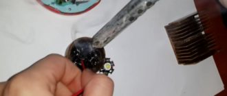
You can use a carbon rod from a battery as an electrode, but a graphite brush from an electric motor is better. Several shallow holes are drilled in it for twists of different diameters. They will keep the drop of copper from sliding off, which often happens when using a battery rod.
A heat sink strand clamp is usually made from old pliers by attaching a welding strand to one of the handles. Its end is ground off, a copper sleeve is put on and soldered, and a wire is attached to it. Insulating heat-shrinkable tubes are placed on top of the handles. To tightly grip the twists, holes of different diameters are made in the jaws of the pliers.
For ease of transportation, a handle, such as a door handle, is attached to the top of the casing.
The legs from the radio equipment are screwed from below. If you turn on the throttle in series with the electrode, the welding will become softer. On large machines for welding large cross-section wires, a current regulator is installed. If desired, it is better to buy it in the form of a separate unit, since it will not be possible to do it yourself without a thorough understanding of electronics.
Technology for welding copper strands with a homemade apparatus
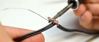
The insulation is removed from the ends of the wires at a distance of 30 - 60 mm and cleaned to a shine. Then they are twisted together in one direction. To ensure that the wires are the same length, the end of the twist is cut off.
Having secured the twist in the heat-removing clamp, touch its end with an electrode and immediately withdraw it by 0.5 - 1 mm. The resulting arc melts the copper, which forms a ball-shaped drop. After its formation, welding is stopped immediately, otherwise the insulation of the wires will begin to melt, and the metal at the seam will become porous. After cooling, the exposed ends are wrapped with insulating tape or covered with heat shrink tubing.
If a self-made device works with an electrode made of a graphite brush with pits for twists, difficulties arise when combining them. Therefore, it is recommended to install a power button on the holder. It is pressed when the twist is inserted into the hole and released after the ball has formed, holding the electrode in place for a few seconds so that the copper drop does not slip off.
Source: https://svarkaprosto.ru/oborudovanie/apparat-dlya-svarki-mednykh-provodov-svoimi-rukami
Welding machines: classification
Any welding machines can be electric or gas. It’s worth saying right away that homemade welding machines should not be gas. Since they include explosive gas cylinders, you should not keep such a unit at home.
Therefore, in the context of self-assembly of structures, we will talk exclusively about electrical options . Such units are also divided into varieties:
- Generator units are equipped with their own current generator. A distinctive feature is its large weight and dimensions. This option is not suitable for home needs, and it will be difficult to assemble it yourself.
- Transformers - such installations, especially the semi-automatic type, are very common among those who make welding equipment themselves. They are powered from a 220 or 380 V network.
- Inverters - such installations are easy to use and ideal for home use; the design is compact and lightweight, but the electronic circuit is quite complex.
- Rectifiers - these devices are easy to assemble and use for their intended purpose. With their help, even a beginner can make high-quality welds.
How to make an inverter-type welding machine
To assemble an inverter at home, you will need a circuit that will allow you to comply with the necessary parameters. It is recommended to take parts from old Soviet devices:
- transistors;
- diodes;
- chokes;
- finished transformers;
- capacitors;
- resistors;
- thyristors.
The following parameters can be selected for the device:
- It must work with electrodes whose diameter does not exceed 5 mm.
- The maximum operating current is 250 A.
Source: https://moy-instrument.ru/instrumenty/svarochnyj-apparat-svoimi-rukami-iz-transformatora.html
DIY welding machine: simple assembly instructions
Due to the fact that ordinary people often need to work with metal in everyday life, many people use welding units. But not everyone can afford to purchase expensive equipment, which is why the question arises of how to assemble a welding machine with your own hands. The manufacturing process will differ depending on the type and design features of the welding device.
Types of Welding Machines
The modern market is filled with a fairly wide variety of welding machines, but not everything is advisable to assemble with your own hands.
Depending on the operating parameters of the devices, the following types of devices are distinguished:
- on alternating current - delivering alternating voltage from the power transformer directly to the welding electrodes;
- on direct current - producing constant voltage at the output of the welding transformer;
- three-phase – connected to a three-phase network;
- inverter devices - delivering pulsed current to the work area.
The first version of the welding unit is the simplest; for the second, you will need to modify the classic transformer device with a rectifier unit and a smoothing filter. Three-phase welding machines are used in industry, so we will not consider the manufacture of such devices for domestic needs.
An inverter or pulse transformer is a rather complex device, so to assemble a homemade inverter you must be able to read schematics and have basic skills in assembling electronic boards.
Since the basis for creating welding equipment is a step-down transformer, we will consider the manufacturing order from the simplest to the more complex.