Features of mechanized welding technology
The permanent connection of materials by welding is one of the least time-consuming operations in terms of material and energy consumption. In addition to the common electric arc welding, there are mechanical welding and thermomechanical welding.
Classification of mechanized and automated processes
It is customary to divide technological processes into cold and high-temperature ones. The latter are more common and are a modernized prototype of manual arc welding with a flux-coated electrode.
Mechanized arc welding eliminates forced limitations in productivity, protection of the weld surface and metal of parts, and reduction of temperature deformations due to uneven heating.
Arc plasma
Welding of parts is carried out using a local plasma flow. The temperature range of the flow of hot gases is 5–30 thousand degrees. The density and refractoriness of metals do not play a significant role .
The thermal effect of the arc is supplemented by the energy of the expanding gases. Usually this is argon in its pure form or mixed with helium. They prevent atmospheric air and other oxidizing agents from entering the work area. Currents of different polarities are used.
Equipment power gradation:
- Up to 25 A – localization of heating, elimination of burns and warping of thin-walled elements, destruction of the aluminum oxide film.
- Up to 150 A – the metal melts at a given depth without damaging the boundary areas.
- More than 150 A – through penetration of high-strength and refractory steels occurs.
Technological mechanized and automatic lines provide advantages in speeding up the procedure by 3–4 times compared to manual machines for precision welding . Labor-intensive soldering gives way to microwelding:
- The seam does not need to be cleaned or leveled.
- There is no need to prepare the surface before welding.
- No temperature deformations.
- Versatility - welding of non-ferrous and ferrous metals, cast iron is available.
- Safety.
Mechanized under a layer of flux
Ignition of an electric arc under a layer of mechanically applied granular flux allows welding with a front width of up to 100 mm. In this case, it is assumed to use a multi-electrode mouthpiece or gas-discharge electrodes. Flux based on manganese silicate is supplied from the hopper to the specified weld width. The welding speed reaches 100–300 m/hour .
A protective measure is provided - the creation of excess pressure of a protective gas bubble. The thermal background of the tail part of the alloy of the weld pool is reduced without sudden temperature changes, which counteracts the occurrence of microcracks. Metal spattering is limited and does not exceed 2%.
Advantages of the method:
- The melt is alloyed and deoxidized due to flux components.
- Compared to manual welding, the speed changes tens of times.
- Arc stability.
- Contact with atmospheric oxygen and nitrogen is excluded.
Semi-automatic arc welding with consumable electrode
Welding of critical structures in any spatial position using semi-automatic hose welding machines with synchronized feed of filler wire is the leader in terms of accessibility. They are manufactured in accordance with GOST 18130-79 E.
The low cost and reliability of stationary and portable devices gives a performance gain of up to 8 times , the use is justified by the remarkable capabilities:
- Forced or natural cooling of the burner.
- The arc zone is protected by an inert gas cloud or flux, or self-shielding flux cored wire is used.
- Steel filler electrode wire is solid or cored, aluminum is solid.
- The types of feeding and adjusting the speed of wire exit from the reel vary.
The safety gas environment is predominantly represented by argon, helium, and mixtures. For low-carbon steels up to 40 mm thick - carbon dioxide. Water or air forced cooling extends the service life of the tungsten infusible electrode.
Automatic orbital system
Stationary and mobile orbital welding complexes are controlled by a computer program. Operating personnel do not interfere with the technological process .
Automatic argon-arc stations are equipped with a stationary burner; rotation of the part around an axis is associated with size limitations in terms of length and total weight of the product.
The orbital system does not have this drawback. It is used for end-to-end connections of trunk pipelines and flange connections in hard-to-reach places. The manipulator moves the burner along a given path, making oscillatory movements to uniformly fill the cutting. The body of the workpiece remains in a static state.
The multi-pass head is installed along guide rings. Mains supply voltage 230–500 V. Pipe size ranges:
- Ø25 –89 mm;
- Ø60 –168 mm;
- Ø168 –1800 mm.
Thermomechanical
Various partially mechanized welding techniques involve compression with simultaneous exposure to a local heat source for joint plastic deformation of the mating surfaces in the zone of greatest electrical resistance. The general term resistance welding combines three different methods:
- Butt welding – the ends of blanks with a compact cross-section are heated and compressed, achieving plastic deformation of both parts of the product over the entire area. There are 2 methods:
- Resistance welding is the joining of homogeneous alloys of small cross-sections of complex shapes with preliminary processing of the ends and precise adjustment of the cross-sectional area.
- Flash welding does not require end preparation. The joints are heated until they melt. Oxides and contaminants are squeezed out of the joining zone during compression.
- Spot and roller (seam) welding are mainly used for lap welding of sheet materials. The only differences are in the size of the contact. The point connection fixes the workpieces in individual areas. Roller - continuous seam. Equipment for mechanized welding is schematically represented by a pair of electrodes that exert pressure on the sheets. Pulsed heating with metal melting and mutual penetration of the cast core of the weld point occurs in a fraction of a second. Compression prevents partial flow of the melt.
- Friction welding is a high-performance method of joining dissimilar alloys. It is actively used for the production of end cutting tools. Shanks made of structural steels are connected to high-speed alloys. The ends of the rotating and stationary workpiece are heated to plastic flow under pressure by friction. Settlement (compression) after stopping rotation creates a strong monolithic connection.
- Diffusion welding is carried out in a vacuum chamber; the degree of vacuum affects the rate of diffusion. A compressive force is applied at the junction. If necessary, electrical contact, induction or radiation heating is provided. Accelerating the mutual penetration of particles is solved by chemical compositions and the use of auxiliary materials. It is achievable to obtain layered structures from poorly compatible materials based on diffusion welding.
Bottom line
Among the 35 types of creating strong contacts based on soldering and welding, there are techniques for non-metallic materials and optical fibers.
Source: https://svarka.guru/vidy/mehanizirovannaya-svarka.html
Welding robots: features and types of mechanized welding
A welding robot is an integral part of the production of any metal products. It is often used when welding cars, large metal structures, and is also used on giant conveyors with multi-batch products.
The use of robots greatly simplifies the process of manufacturing large batches of identical parts. They produce everything quickly, apply perfect seams, do not require wages and work without a lunch break. But this is not all the advantages of this equipment over human labor.
The main advantage is that welding robots are capable of producing huge volumes of parts in a short period of time, which will be completed without defects or violations. But still, to understand what these systems are for the welding process.
general information
Robotic welding is a type of automatic welding process, the main essence of which is the use of programmable robots in production instead of conventional welders. This type of welding is widely used in large enterprises where various metal products are constantly produced in large volumes. Robots make it possible to weld and produce large batches of parts and structures in a short period of time.
The use of automated machines makes welding automated, which ultimately ensures a permanent connection between metal workpieces. In addition, thanks to them, the workpieces are constantly moved and processed, all of which has a positive effect on the quality of the seam. But to ensure full operation of this equipment, additional human participation is required. The operator must prepare materials for welding, as well as program the device.
Note! In modern production, welding robots are usually used when working with an electric arc in a shielding gas environment. These products are perfect for laser, plasma, resistance, and hybrid welding methods.
Features of the welding robot device
Many models of welding robots use elements that allow them to function fully for a long time. This is achieved through the introduction of special electronic systems, which have a technically advanced device. This is what prevents the robot from stopping its work process during power outages and unstable voltage.
Welding robots can independently position parts in automatic mode, which has a positive effect on the quality of the joint. The dimensions of the workpieces are not important, because the robot’s arm can adapt to any parameters of the welded workpieces.
It is worth noting! An automated robot welder is a unit that is mounted on a base. It is equipped with a hinge mechanism that ensures easy rotation and direction of the device in the desired direction.
The base of the equipment contains important elements from the list below:
- current source;
- converter;
- feeder;
- display and programming console;
- a cylinder filled with inert gas;
- manipulator. It can lift parts weighing up to 25 kilograms.
Each type of mechanized welding has specific software. It is there that the control panel sets the parameters of the welding process and the metal workpiece that needs to be welded. Often, in addition to the device, special books and video materials are provided for self-study.
Additionally, special holders may be included. They allow the robot to position and fix the workpiece during the process. Robot welding can not only connect parts, but also clean them, as well as chamfer and cut. The equipment performs everything independently, including preparatory operations.
Mechanized welding is capable of performing any type of welding and cutting. Robots often perform spot, electric arc and argon arc welding, including submerged arc welding. In addition, when using robotic devices, the risk of danger to human health at work is greatly reduced, because they are not involved in the process.
Advantages of robots for welding
Robotic welding has made life much easier for large enterprises that constantly need to produce large volumes of metal products. Thanks to this process, the speed performance of similar connections has increased without reducing quality.
The use of welding robots ensures precise positioning of parts and their precise movement, and the presence of programmed systems in the devices makes the process continuous and accurate. All this allows these devices to replace several professional welders, and they can also operate continuously for a long time.
Robotic gas shielded welding has other equally important advantages:
- Robots can perform the same types of work consistently without compromising quality. But people cannot perform the same type of work for many hours.
- Automated machines produce high quality seams and can be reconfigured mid-production.
- Robots are a profitable proposition for large enterprises. They pay for themselves fairly quickly, this is due to their high performance indicators.
- Devices of this type require only maintenance. But people need to pay wages, and don’t forget about taxes.
- Robots are easy to customize. If the operator has studied all the features of setting up the device, he can do this in a matter of minutes. Even beginners can do this work, but it’s worth first studying the connection algorithm and setting up the robot to the parameters of the selected welding and parts.
- Robots are capable of working for a long time without interruption. All this increases the quantity of products produced. An ordinary welder is limited in his capabilities; after long work, he definitely needs rest. Also, the quality of work depends on his physiological state. But robotic technology never fails; it accurately performs assigned tasks without interruption or interruption.
- The use of this device allows you to obtain thin and even seams. This is ensured by maintaining the arc at a distance of 2 mm.
- The equipment allows you to save voltage and consumables.
- Provides increased productivity growth with predictable results, no need for frequent quality control.
Flaws
However, it is worth considering that mechanized welding in shielding gases has negative qualities. Of course, compared to the advantages, there are not so many of them, but they still exist.
Among the main disadvantages are:
- The first and significant drawback is the high price of the devices. Of course, they quickly pay for themselves, but not every production can purchase the required number of robots that can replace welders.
- Robots are only suitable for assembly line production. For other types of production, these devices are not particularly suitable; they will be ineffective. This means that they will not be able to recoup their cost soon.
- Before using robotic welding equipment, it is necessary to train welders how to use it correctly. This takes some time; the operator must understand the correct robot control algorithm.
- To get good results you need to set the correct settings on your device. However, if the welder is tired or insufficiently trained, problems may arise when using robotic devices and the results will be of poor quality.
- There are welding modes in shielding gases, during which active products of activity and the environment can cause harmful effects on human health. For this reason, work is carried out in an isolated space. The welder sets up the program, starts the robot and leaves the room, the whole process is carried out independently.
Types of robots for welding
Robotic welding devices allow high-quality welding of metal products. These devices perform large volumes in a short period of time, but for this they need to be configured correctly. It is worth considering that welding devices differ in height, length of the operating arm, and number of rotating sections.
Welding robots can be divided depending on the type of welding process they can carry out:
- mechanized welding in shielding gases. It is carried out in an environment of argon and carbon dioxide using a consumable electrode (wire). In accordance with the wire diameter and current strength, these devices can be used on thin and thick plates and structures. They are used when working on conveyors when assembling cars;
- mechanized welding in a carbon dioxide environment using tungsten non-consumable electrodes. The use of these elements is suitable for obtaining smooth seams. They are suitable for products made of stainless steel, copper;
- robotic devices for the resistance welding process, which is carried out between two carbon-based electrodes. They are used in mechanical engineering and radio equipment. The installations allow for quick assembly of body parts for different devices;
- devices that perform seams using a plasma jet. They are used for work where the metal products being welded are not influenced by other methods;
- equipment for pipeline welding. When welding, a consumable submerged electrode is necessarily used. This creates large areas of pipe lines. They are moved to the laying areas, where they are manually connected;
- robots that perform welding using lasers. They are used where high-speed welding is required without releasing toxic components into the open air;
- hybrid models that can perform several types of welding.
It is worth noting! A striking example of robotic devices for the welding process is manipulative electric arc shop welding. Its quality may depend on the composition of the welding wire, the type of shielding gas used, the uniformity of the filler or welding wire and other conditions.
Setting up the robotic device
Mechanized welding technology requires calibration. This process is carried out in three stages:
- calibration of external axes of movement of the robot manipulator;
- coordination of instrument movements;
- environmental coordination.
Important! Proper setup of a welding robot is essential for it to function properly and help speed up production. These measures are carried out by the remote control and display.
The setup process begins with calibration of the equipment axes. This procedure is performed once when installing the robot into position. Checking the range of motion and compliance with these indicators is carried out on the device screen. If there are even slight violations or deviations, the equipment will lay a welded joint in the wrong place.
Afterwards the coordinates are set. This is the substrate on which the welding head works, and other devices that are used to grip and press the workpieces. If all the actions of the equipment are uncoordinated, then in the end all manipulations with the workpieces will be performed in the wrong place.
In order for mechanized arc welding to be able to perform high-quality welding of a large volume of workpieces, it is imperative to establish the coordinates of the environment. Thanks to the introduction of this data, the equipment will be able to move freely over the product, accurately performing the assigned operations. It will not collide with other elements during the production process.
All modes of mechanized welding in shielding gases allow welding to be carried out quickly and efficiently. The use of robots in production greatly speeds up the process of manufacturing large batches. For this reason, this equipment is used in conveyor technologies, where it is necessary to produce the same type of workpiece in large quantities. Correct configuration and precise control allows the equipment to operate for a long time without interruption, interruptions or reduction in production quality.
Interesting video
Source: https://osvarka.com/vidy-i-sposoby-svarki/mekhanizirovannaya-svarka
Mechanized welding
Mechanized (or semi-automatic) welding is arc welding in which the supply of a consumable electrode and the movement of the arc relative to the product are performed using mechanisms. It can be used to make any welded joints: butts, corners, T-joints, lap joints, etc.
Automatic arc welding is called arc welding, in which the initiation of the arc, supply of the electrode and movement of the arc relative to the product are performed by mechanisms without direct human participation, including according to a given program.
Figure 17.3 shows a diagram of the formation of a welded joint for the types of welding under consideration. It is marked: 1 – electrode wire; 2 – nozzle (nozzle); 3 – current-carrying tip; 4 – gas (flux); 5 – arc; 6 – hardened slag; 7 – seam; 8 – weld pool; 9 – base (welded) metal.
In mechanized and automatic welding, the formation of a welded joint occurs as follows. The heat of the arc melts the electrode and the base metal, drops of molten metal from the end of the electrode fall into the weld pool, where they mix with the molten base metal. The liquid metal of the weld pool is subjected to metallurgical processing using
gas or flux (this is the difference from manual arc welding). That is, it is deoxidized and doped. When the arc moves along the edges being welded, the weld pool also moves. In its tail part the metal cools, crystallizes and a welded joint is formed.
The following types of mechanized (automatic) welding are distinguished.
1. -carbon , as well as low-alloy steels are welded in carbon dioxide and its mixtures with oxygen. Steels up to 40 mm thick are welded in carbon dioxide, and up to 80 mm thick in gas mixtures. Protection with a mixture of gases improves the technological and metallurgical characteristics of the welding process. The consumption of carbon dioxide depends on the power of the arc, the stick out of the electrode, and the air flow in the room where welding is performed.
2. Aluminum, magnesium, titanium and their alloys can be welded in inert gases Low- and medium-carbon, low-, medium- and high-alloy structural steels are welded.
The use of these gases is advisable, since argon has a density almost 1.5 times greater than air, and helium has a density significantly less than air and argon.
In addition, argon and helium do not form chemical compounds with metals, so any metals and alloys can be welded in these gases.
3 . Low- and medium-carbon, low-, medium- and high-alloy steels, cast iron, titanium, copper, aluminum and their alloys are welded under flux
Flux is a powdery material that, when welding, performs the same functions as coating an electrode during manual arc welding. The basis of the flux is manganese silicate SiO 2 ·MnO. Depending on the manufacturing method, fluxes come in two types: fused and unfused. Fused ones are produced by fusing the original components in furnaces.
Unfused fluxes include ceramic and sintered fluxes. Ceramic fluxes are made from powdered materials bonded into grains with adhesives, such as liquid glass. Sintered fluxes are produced by sintering initial powdered materials at high temperatures, followed by crushing the particles to specified sizes.
During welding, part of the flux melts, and after hardening it forms a slag crust. The unmelted part of the flux after screening is reused.
4. Low-carbon and low-alloy steels in particular, stainless steels, copper alloys.
They can weld steel up to 40 mm thick. Flux-cored wires are a metal sheath filled with a charge . Some cross sections of them are shown in Figure 17.
4: a ) tubular, b ) tubular with overlap, c ) and d ) – complex sections.
The simplest design is flux-cored wire with a tubular cross-section. To increase the rigidity of the wire, as well as to change the ratio of the components of the sheath and charge materials, wires are used in which the edges of the metal sheath are bent into the internal cavity. The composition of the shell metal is selected depending on the metal being welded. Components are introduced into the flux-cored wire charge that can perform the following functions:
– protection of molten metal from interaction with oxygen and nitrogen in the air;
– deoxidation and alloying of molten metal;
– stabilization of arc combustion;
– improvement of seam formation.
Three types of flux-cored electrode wires are used: self-shielding, for welding in carbon dioxide, for submerged arc welding. Welding with self-shielding flux-cored wires is distinguished by the highest technology, since there is no need to use shielding gases and fluxes.
Welding equipment . For mechanized and automatic welding, semi-automatic and automatic machines are used, respectively, equipped with current sources to power the arc.
The machines perform the following functions: arc initiation and automatic control of the welding process; mechanized feeding of electrode wire at a speed equal to the melting speed; mechanized movement of the arc relative to the edges being welded; supply of flux or gas to the arc zone.
The machine consists of two main devices: a tractor or self-propelled head and control equipment. Automatic welding machines in shielding gases, in addition, have gas equipment, which includes a gas reducer, a cylinder with carbon dioxide, a gas heater and a dryer designed to purify the gas from moisture.
The tractor feeds the electrode wire and also supplies current to the welding site. In the feed mechanism of automatic and semi-automatic machines for welding with electrode wires, there are usually two feed rollers, one of which is driving and the other is pressing; the electrode wire is clamped between these rollers. It is unwinded from the cassette, pushed through the hose and fed through a conductive device into the arc zone.
The tractor for submerged arc welding has flux supply and removal systems, and the tractor for gas shielded welding has a special gas-electric torch, which is designed to direct the electrode wire into the zone, supply welding current to it and supply shielding gas to the arc zone. When submerged arc welding, instead of a torch, a holder is used, on which a hopper for supplying flux is attached.
Application of mechanized and automatic arc welding. Mechanized welding can be used to apply not only straight, but also curved seams, as well as short-length seams in hard-to-reach places. Weld metal of small and medium thickness. These types of welding are used for various work, including repair work. In mass production, it is advisable to perform straight and circumferential welds with a length of more than 300–500 mm using automatic welding.
In transport engineering, mechanized and automatic arc welding is used in the production of cars and locomotives. The center beams are welded on mechanized production lines using submerged arc welding machines. Car frames are welded by automatic welding in carbon dioxide on specially equipped tilters. In tractor and agricultural engineering, carbon dioxide welding is used to perform up to 75% of all welding work.
Automatic submerged arc welding and carbon dioxide welding are widely used in pipe production for the production of large-diameter straight-seam and spiral-seam pipes.
Mechanized submerged arc, carbon dioxide and flux-cored welding is widely used in the construction of blast furnaces, petroleum product storage tanks, bridge construction, shipbuilding, etc.
End of work -
This topic belongs to the section:
APPLIED MECHANICS
BELARUSIAN STATE UNIVERSITY OF TRANSPORT Department of Technical Physics and Theoretical Mechanics
If you need additional material on this topic, or you did not find what you were looking for, we recommend using the search in our database of works:
What will we do with the received material:
If this material was useful to you, you can save it to your page on social networks:
20.3. Mechanized arc welding
The most effective means of increasing the productivity of welders is the use of mechanized hose welding. This type of welding is similar in many ways to manual arc welding. The welder holds the torch of the hose holder in his hand and guides the welding wire into the joint or corner of the fillet joint.
If necessary, he manipulates the wire, giving it back-and-forth movements along the seam or transverse movements. Starting the shielding gas, turning on the current, and activating the welding wire feed mechanism is carried out by the welder by pressing a button or start valve on the torch.
Only the wire feeding operations, the process of starting welding and finishing it with welding the crater, are mechanized.
Mechanized welding in carbon dioxide is widely used in the manufacture of structures.
For mechanized welding in carbon dioxide, special installations are used, consisting of power sources with a control unit, a wire feed mechanism, a wire reel or cassette, a gas tube with equipment and a hose holder with a torch.
The hose holder includes a welding cable, control wires, a wire feed spiral and a gas tube, connected into a common package 2.5-3 m long. Figure 20.6 shows the placement of devices for welding in carbon dioxide in a workshop on a cantilever full-rotary floor installation.
To move the heavy wire feed mechanism with the wire spool, it is placed on the installation console. The wires and gas tube are connected by a common hose (sleeve).
The welding wire, control wires and gas tube pass through the tubular console and down the tubular stand, and then are routed along the guide sheet between the legs of the stand to the power and gas supply posts. This design allows the welder to perform work at a distance of up to 10 m.
During installation work, mobile carts on wheels are used, on which a feed mechanism and a cassette with wire are placed.
However, welding in carbon dioxide has not become widespread during installation due to the difficulty of moving equipment in different places of structures and the unreliability of welding due to the blowing off of the shielding gas.
Mechanized hose welding with self-shielding flux-cored wire is successfully used in the manufacture and installation of structures. The flux cored wire welding station consists of a power source, a control unit, a feed mechanism, a hose holder with a torch and a welding cable with control wires.
Due to the needlessness of additional gas protection, this type of welding significantly simplifies the equipment and the entire process of welding work. However, the need to move the feed mechanism and the cored wire reel along with the hose holder causes certain difficulties when installing structures.
Nevertheless, welding with self-shielded wire is increasingly being implemented in installation work and provides a significant increase in labor productivity.
MECHANIZED ARC WELDING
arc welding, in which the supply of a consumable electrode (filler metal) is supplied or carried. the movement of the arc and the product is carried out using mechanisms. If welding is carried out only by mechanisms, without direct welding. human participation, including according to a given program, then it is called. automatic arc welding. Methods of M.D.S. are widely used. submerged and in protective gases. M.d.s. performed using welding heads and arc welding tractors.
. 2004.
See what “MECHANIZED ARC WELDING” is in other dictionaries:
- mechanized arc welding - NDP. semi-automatic arc welding Arc welding in which the supply of a consumable electrode or filler metal, or the relative movement of the arc and the workpiece, is carried out using mechanisms. [GOST 2601 84] Inadmissible, not recommended Mechanized arc welding
Source: https://domvpavlino.ru/mechanized-welding/
Automatic and mechanized welding in carbon dioxide environment
Carbon dioxide welding is a type of arc welding. Unlike manual covered electrodes, the arc burns between steel wire and the workpiece. The wire is fed into the arc zone by an automatic feeder.
The feeding mode is set based on the wire diameter and the current component of the set mode. The arc site is protected from active atmospheric oxygen by carbon dioxide (CO2), which is supplied to the combustion zone through the channels of the hollow mantle. The burner diagram is shown in Figure 1.
The polarity of the electric arc is reversed with a plus at the tip.
Rice. 1. MAG burner device. 1 - steel wire; 2- current-carrying tip; 3- output nozzle; 4- shielding gas; 5 — welding arc; 6—melt bath; 7 - welding seam.
Types of welding
There are two types of welding in carbon dioxide - semi-automatic and automatic or mechanized welding. With semi-automatic feeding, the mouthpiece is guided to the arc burning zone along the welding seam using the welder's hand. The machine carries out welding automatically according to the specified mode.
To carry out work with mechanized welding, the following equipment is used: semi-automatic machines of the brands PDG-516, PDG-508, PDG-415, PDG-252. Rectifiers with a rigid characteristic (maintaining constant current regardless of the position of the arc relative to the part) are used as a source of electric current.
Rectifiers VDU - 504, VDU-506 can also be used.
Semi-automatic PDG 315 "Buran"
Apparatus for semi-automatic welding and partially mechanized fusion welding of carbon and alloy steels, aluminum with automatic wire feeding in a shielding gas (carbon dioxide CO2 and its mixtures) from 0.8 - 1.6 mm. Aluminum is boiled in argon. The model is notable for its characteristics: the device produces 300A without any problems.
It has two modes and 6 stages of power adjustment, for a total of 12 adjustments. There is a switch for short and long seams (locking the feed button on the holder). Equipped with a digital display to monitor current. On the front panel there is a multi-position potentiometer for adjusting the wire feed. Gas and wire supply indicators.
Fig.2. Semi-automatic PDG-315 “Buran” with a connected torch cable.
The device is on wheels, which is very convenient for transportation. Weight 120 kg.
The device is supplied with a 300A cable, a cable plug, a 15 kg wire reel, and a torch with a replaceable tip. The torch has a movable joint at the cable connection point, which greatly facilitates the work of the welder.
The device is equipped with a 4-roller feed mechanism, which is designed to push the wire into the combustion zone.
- Rated network voltage: 3ph x 380V, 50 Hz,
- Electrical power: max, 12.9 kW
- Welding current at PN 40% - 300A, PN 60% - 270A, PN 100% - 200A;
- Open circuit voltage 45V;
- Number of current control stages 2 x 6;
Voltage regulation range 20 -34V.
Introduction to burners
The welding torch MIG (metal inert gas), in the second - MAG (metal active gas) can be safely called one of the important components of the technology of partially mechanized welding (semi-automatic). The comfort of the welder’s work, and therefore quality and productivity, depends on the quality of this device. partially mechanized welding technology
Fig. 3 MAG burner device with equipment: hose and connector.
Torch connectors
There is a single standard tip for connecting the hose to the device, which has been standard since 1970. A single connector allows devices to be equipped with cables from different manufacturers.
Fig.4. Standard "Euro" MAG burner connector.
Purpose of burners
The design of MAG torches differs in current supply power, which are sorted by numbers: No. 15, No. 24 - No. 36, nozzle diameter and wire feed diameter, designed for welding in the maximum current range from 150 to 300 A, respectively, and are air-cooled.
For more powerful devices with high currents, water cooling is provided.
This type is used on devices together with cooling stations. The water pressure in them is 2-4 bar, (with liquid circulation 1.6 l/min.) (Attention! The use of water-cooled burners without water is strictly prohibited.
Burner device
The device allows the welder to work with different wire thicknesses from 0.6 to 1.6 mm.
The standard is designed for a 60% duty cycle from 120A to 500A. The main parts of the burner (see Fig. 3) are:
- a gander, inside of which there is a channel for drawing wire and a hole for gas supply; tip made of a special copper alloy;
- a nozzle through which gas is supplied to the arc combustion zone;
- cable - a hose inside which there is a gas supply tube, a wire channel. For water-cooled burners, the cable-hose additionally contains channels for water circulation.
Consumables
Fig.5. Burner consumables: nozzles and tips of various designs and diameters.
For welding holders, consumables are: tips, nozzles, channels.
The period for replacing tips and nozzles depends on the professionalism of the welder and the intensity of the equipment. Tips are changed much more often than other parts.
In order to extend the service life of consumables, manufacturers recommend using a non-stick spray - an aerosol that prevents the adhesion of scale.
Rice. 6. Channels for wire feeding. Each color corresponds to a specific diameter.
Wire feed channels
The wire feed tubes into the welding zone may be different. So for steel, metal is used - twisted. Teflon-coated plastic will work with aluminum. Slippery Teflon walls make the supply of consumables smooth and predictable. The wire tube is selected not only by the material from which it is made, but by the diameter of the wire:
- For steel wire with a diameter of 0.6 - 0.8 mm, the color is blue;
- For diameter 1 - 1.2 mm. - red;
- For 1.2 - 1.6 mm - yellow.
Teflon:
- Diameter 0.6 - 0.9 mm. - blue;
- For 1 - 1.2 mm. - red;
- For 1.2 - 1.6 mm - yellow.
The length of the burner cable can be 3, 4, 5 m. To obtain strength and fire resistance, the tips can differ in design: they are made of copper alloys with the addition of zirconium or chromium.
Welding defects
During the welding process, poor-quality seams are possible, which arise from the incorrectly selected mode. Defects in shape and size include:
- not fullness;
- uneven width and height;
- lumpiness and swelling;
- saddles and constrictions.
Below are common seams that occurred due to an incorrectly selected mechanized welding mode.
Fig.7. Types of poor-quality seams due to incorrect welding conditions.
In addition to the incorrect welding mode selection, weld defects are possible in welded joints. Defects can be external and internal. Depending on the causes of defects, they can be classified into two groups:
- Defects associated with the process of metal melting and its crystallization with subsequent solidification. Such defects include: cracks in the weld metal and heat-affected zone, slag inclusions, porosity, thermal changes in the properties of the metal in the weld zone with the formation of uneven weld tension.
- Defects that occur during seam formation. Such defects arise due to an incorrectly selected welding mode, improper preparation of parts or poor quality preparation of structures.
Source: http://themechanic.ru/mehanizirovannaja-svarka/
Mechanical types of welding
Mechanical types of welding include cold and ultrasonic welding, as well as friction and explosion welding.
1. Cold welding
This type of welding is used to join very ductile metals (aluminum and its alloys, copper, lead, tin, etc.) (Fig. 1).
Cold welding is pressure welding with significant plastic deformation without heating the parts being welded by external heat sources. It is divided into three types: point, suture and butt.
Rice. 1. Cold welding diagram
Using cold spot welding, sheet materials are overlapped or joined together (Fig. 2).
Rice. 2. Schemes of cold welding with forces normal to the joint surface : a, b – overlap; c, d – butt; 1, 2 – parts to be welded; 3 – clamps
Cold welding is mainly used to weld homogeneous or inhomogeneous metals and alloys that have high ductility at normal temperatures. High-strength metals and alloys are not cold welded, since this requires very large specific forces, which are practically difficult to implement.
Alloys of aluminum, cadmium, lead, copper, nickel, gold, silver, zinc and similar metals and alloys are well welded. The advantages of this method include low energy consumption, insignificant changes in the properties of the metal, high productivity, and the possibility of automation.
For cold spot welding, any press can be used (screw, hydraulic, lever, eccentric), in addition, specialized installations for cold butt welding (Fig. 3).
Rice. 3. Electro-pneumatic apparatus for welding rods, wire and strips of non-ferrous metals with a diameter of 5 to 12.5 mm (a) and the length of welded copper and aluminum rods (b)
Seam cold welding is used to connect sheet materials with a continuous seam (Fig. 4).
Rice. 4. Scheme of seam cold welding : 1 – metal to be welded; 2 – support rollers; 3 – roller punches (protrusions)
Cold butt welding is used to connect the rods along the surface of the butt ends.
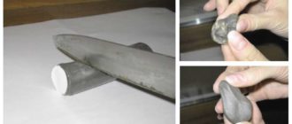
Rice. 5 Friction welding
Friction welding uses the conversion of mechanical energy into thermal energy. When metal workpieces 1 rotate relative to each other, one is installed in a fixed clamp 2, and the second in a movable clamp 3 (Fig. 5), their ends heat up due to friction of the contact surfaces. Heating is carried out to a plastic state, and then an axial force P is applied.
The formation of a welded joint occurs as a result of the formation of metallic bonds between the contacting surfaces. Oxide films present on metal surfaces at the connection point are destroyed by friction and removed as a result of plastic deformation in radial directions.
The main parameters of the friction welding process are: the speed of relative movement of the surfaces being welded; the magnitude of the specific pressure applied to the surfaces being welded; the amount of plastic deformation, i.e. settlement.
The heating required for welding, all other things being equal, is determined by the rotation speed and the magnitude of the axial force.
2. Ultrasonic welding
Pressure welding carried out under the influence of ultrasonic vibrations is called ultrasonic welding (USW) (Fig. 6). The implementation of ultrasonic welding consists in the application of high-frequency vibrations (16 - 20 kHz) to the workpieces being welded. Tangential stresses arise in the workpieces, causing plastic deformation of the material of the surfaces being welded.
An increased temperature (0.4 - 0.6) Tmel develops at the joint, depending on the properties of the materials being welded. This temperature promotes the appearance of a plastic state of the materials being welded and their connection. At the welding site, during the cooling process, joint crystals are formed, ensuring the strength of the welded joint.
At the same time, under the influence of ultrasound, oxide films on the surfaces of the workpieces are destroyed, which also facilitates the preparation of the joint.
Rice. 6. a – ultrasonic welding diagram , where: 1 – converter; 2 – transformer; 3 – working tool; 4 – tip; 5 – product to be welded; 6 – support; b – ultrasonic welding along the contour, where : 1 – waveguide; 2 – replaceable hollow pin; 3 – replaceable clamping pin; 4 – clamping support; 5 – product to be welded
Technological capabilities of USS: joining metals without removing surface films and melting; especially good weldability of pure and ultra-pure aluminum, copper, silver; combining the thinnest metal foil with glass and ceramics. Most known thermoplastic polymers are welded by ultrasound. For a number of polymers, ultrasonic bonding is the only possible reliable joining method.
With ultrasonic welding, in principle, there are no restrictions on the lower limit of welded thicknesses of various metals. It is also possible to join with a significant difference in the thickness and properties of the materials being welded (for example, in a metal-glass joint there can be a ratio of 1: 1000 or more).
Ultrasound systems are also characterized by low energy consumption; the ability to power several welding heads from one generator and the ability to move them over a considerable distance; ease of automation of the process of operation of the oscillatory system; hygiene of the process.
USS methods are used in instrument making, radio electronics, and the aviation industry. In Fig. Figure 7 shows one of the industrial installations for ultrasonic welding.
Rice. 7 . Ultrasonic film welding
3. Explosion welding
Explosion welding can be classified as a type of welding with fusion during short-term heating in air, since in certain areas there are zones of metal heated to melting. However, in other areas the temperature may not be high, and here the process approaches cold welding.
When carrying out explosion welding, the chemical energy of converting an explosive charge into gaseous explosion products is transformed into the mechanical energy of their expansion, giving one of the welded workpieces a high movement speed. Kinetic energy of collision of a moving part with the surface of a stationary part
is spent on the work of joint plastic deformation of the contacting layers of metal, leading to the formation of a welded joint.
The work of plastic deformation is accompanied by the release of heat, due to which, due to the adiabatic nature of the process, at high speeds the metal in the joint zone can be heated to high temperatures (up to the melting of local volumes). Most welding technological schemes are based on the use of a directed (cumulative) explosion (Fig. 8).
Rice. 8. Explosion welding diagram : 1 – detonator; 2 – explosive; 3 and 4 – workpieces to be welded; 5 – base; h – gap between workpieces; H – thickness of the explosive layer
The strength of joints made by explosion welding is higher than the strength of the materials being joined. The prospects and areas of application of explosion welding are determined by the possibility of creating strong connections in the solid phase due to surface metal bonds without the development of volumetric diffusion due to the rapidity of the process over large (20 m2), practically unlimited areas.
This makes it possible to use explosion welding in the manufacture of billets for bimetal rolling, cladding the surfaces of structural steels with metals and alloys with special physical and chemical properties, and when welding workpieces from dissimilar materials. It is advisable to combine explosion welding with stamping and forging. In Fig.
9 shows a successful photograph of explosion welding in the field.
Currently, wide possibilities are opening up for the use of explosion welding to create compositions with intermediate layers that, when heated, play the role of diffusion barriers between the main and intermediate layers. And also to increase the strength and performance of such adapters by means of contact strengthening of the intermediate layers while reducing their relative thickness within unlimited limits.
Rice. 9. Explosion welding in the open area of Pulse Technologies
Source: https://extxe.com/21234/mehanicheskie-vidy-svarki/
What is mechanized welding
Not a single modern production can operate without welding work. Connecting metal components in this way provides the structure with strength and reliability.
If the volume of welding work is not large, then a specialist can easily cope with its implementation independently. You can find out about this on the website http://svarochnyeavtomaty.ru/production/mekhanizirovannaya-svarka/. However, when x is large, this is physically impossible, and then special mechanisms come to the aid of the master, which help speed up the process of welding metal joints.
It is for such purposes that mechanized arc welding was created, which helps a person in his work. The system allows the welder to most accurately connect the metal products that will be welded and position it at an angle convenient for work.
Mechanized assistant
The name itself suggests that this method of welding seams of metal products involves the participation of special mechanisms. With this type of arc welding, the process of feeding the electrode and moving the welding arc is carried out using mechanical equipment.
To perform welding joints of varying complexity, such mechanized equipment is simply necessary in large production. With the help of such units, the welder is engaged in his immediate occupation, without being distracted by extraneous inconveniences.
Mechanized welding allows you to increase the productivity of the welder and ensure the performance of welding work in hard-to-reach places. With its help you can handle even thick metal without any problems.
Types of mechanized welding
Mechanized arc welding is distinguished by the types of gas used in the process. It is divided according to this type:
- carbon dioxide welding - used for welding steels with low and medium carbon content;
- welding in inert gas (argon, helium) - indispensable for welding products made of aluminum, titanium and magnesium;
- welding using flux - this material in powder form is used for welding elements made of steels containing low and medium percentages of carbon, steels of any degree of alloying, as well as cast iron, copper and aluminum.
In any case, mechanized devices are faithful assistants to humans. Every year they are improved and make work much easier, which certainly affects the increase in labor productivity at the enterprise.
Source: http://euroelectrica.ru/chto-takoe-mehanizirovannaya-svarka/
Automatic welding: what is it, types and advantages of technology
Automatic welding has another name, which reveals its essence - submerged arc welding.
It has been one of the most popular metal joining technologies in the industry for a long time. The reason for this is the durability of welding seams and ease of execution. Flux mixtures are used for better adhesion of joined surfaces.
Best of its kind
This is an automatic type of welding with a mechanized method of performing the work process. The physical process is simple and straightforward: a special electric arc melts under high temperature.
Automatic welding drawing.
As a result, the combustion flame is directed to the so-called welding object - the wire, which is located in the direction of the seam itself. The arc burns under the cover of a powerful granular blanket - a flux mixture. Due to the high temperature, they begin to melt in the weld pool.
A special elastic film is formed around it, which is an excellent protection for metal and electric arcs from air penetration and the formation of the main enemy of a good weld - an oxide film.
After the process, during the cooling period, the granular flux mixture turns into slag, which covers the new welding seam, and which must be removed in the simplest way - mechanically.
If the work is semi-automatic, the master needs to take a fairly active part in the process: hold and guide the filler wire, which is fed automatically. In addition, you need to monitor the behavior of the electrode: the direction of its movement and the speed of movement and angle of inclination.
If fully automatic welding is used, then the speed and direction of movement of the electrode is performed automatically. This method requires smooth welding surfaces and fillet welds.
Recently, tandem technology for working with metals has been extremely popular, in which both methods are used, which are carried out parallel to each other in the same plane of the workpiece being welded.
This combination significantly improves the quality of the weld due to the optimal size of the weld pool and the rapid ignition of the electric arc.
What are the benefits of submerged arc welding?
Firstly, little flux mixture is wasted - in other words, resources are saved without losing the quality of the seam. This is due to an efficient design with excellent metal adhesion.
In addition, another factor plays a role: this is a neat and very thin coating of the residual weld seam with a protective layer of slag, which protects it from the negative effects of oxides formed from the air. For connecting, for example, pipes, this is the most optimal welding option without any doubt.
Scheme of automatic arc welding.
This technology has many advantages, it’s easy and pleasant to list them:
- Good speed of operation, which gives good performance of the overall process.
- Excellent savings on consumables: the metal of the electrodes is lost by only 2%.
- The technology does not cause the formation of metal splashes, which also leads to savings in base metal.
- The area where the surfaces connect is well protected from the negative effects of air and the environment.
- Minimal oxide formation due to the use of fluxes.
- Excellent fine-scale structure and aesthetics of the weld seam due to an even arc flame throughout the entire welding process.
- Flux plays the role of the main protector from harmful influences, so there is no need for additional protective devices and methods.
- Intensive cooling of the metal after the process leads to the formation of a stable compound.
- This is a fairly simple method to perform and does not require special training.
Can't do without downsides
The method has much fewer disadvantages, some of them can be regarded as technical features:
- What can we say, automatic welding is an expensive method and therefore not accessible to everyone.
- Difficult to determine the correct placement of material for fixation due to the technical characteristics of the process.
- Not a harmless method for the person who performs it.
- Often you need equipment that is only available in industrial enterprises. This feature makes the technique a rare guest in handicraft workshops.
Where is automatic welding used?
The method is wonderful in terms of versatility and efficiency, so it can be used anywhere: from home workshops to large industrial enterprises, including welding pipes of various calibers and purposes.
Operating principle of an automatic welding machine.
It can be used in the following types of work:
- installation of complex structures;
- joining metals with a large surface area for coupling;
- connection of any metals or alloys up to the connection of workpieces of dissimilar composition.
At one time, when they began to use protection in the form of flux, almost a revolution took place in the industry in the best sense of the word. At first, fluxes were used when working only with low-carbon steel.
The application has expanded and is now widely used in the following cases:
- welding of complex vertical seams with forced or free seam formation;
- installation of pipes of various calibers, including large diameters;
- connection of circumferential welds with a complex workflow to retain the weld pool and spreading of metal, with manual welding, on CNC machines.
Equipment and tools
There are a great variety of automatic welding machines for this method on the market with very different characteristics and purposes. The best and most convenient of them are models whose characteristics include the ability to support wire feed.
Submerged arc welding drawing of metals.
When choosing the optimal model for your work, you need to take into account one more fact: if the length of the electric arc decreases, other parameters, on the contrary, will increase: the rate of melting of metals will increase, the strength of the welding current will increase.
Under such conditions, a special power source with certain current-voltage properties is needed.
If the electrode feed speed decreases, in automatic welding machines the heads with a voltage regulator will instantly adjust and change the arc length. In this case, the current-voltage parameters should decrease proportionally.
If you have a machine in which the electrode feed speed does not change, you will still have to work to find the optimal welding current value. The voltage in the electric arc will also have to be adjusted manually and experimentally by changing the settings of the external power source.
Source: https://tutsvarka.ru/vidy/avtomaticheskaya
Technology for mechanized welding
For automatic and mechanized welding, automatic and semi-automatic devices and devices are used. They are equipped with current sources in order to power the arc.
These machines are designed to perform the following functions:
- excitation and setting of the arc in motion;
- adjustment of the welding process;
- the electrode wire is fed at the same melting rate required for welding;
- the arc moves evenly around the edges being welded.
Semi-automatic equipment has two main devices. Self-propelled head or tractor, as well as control equipment.
Welding machines for welding in gas formations include special gas reducers, cylinders with acids, heaters and dryers, which are necessary to purify gases from excess moisture.
Using a tractor, the electrode wire is fed, and the current is conducted to the welding site. The mechanized welding method using electrode wires usually includes two rollers, one driving and the other auxiliary. They are the ones who securely hold the wire and compress it with the required force. They are wound on special cassettes, so they are pushed through the hoses, and then, using a tog, they are fed into the area where the arc is located.
Automatic submerged arc welding equipment has special systems that remove excess flux. A tractor for welding with shielding gases has a torch that directs the electrode wire to the required area, supplies current to it and supplies gas formations to the desired place. In place of the burner there is usually a holder that supplies flux through a special hopper.
Mechanized and automatic welding and its application
Mechanized welding helps to create straight and curved seams, and also allows welding in hard-to-reach places. Metals must be of medium to small thickness to ensure reliable and high-quality welding.
These types of welding are used for repair and production work.
Circular and straight welds when used in production that are longer than 300 mm are usually performed only using automatic welding equipment.
In transport and engineering production, mechanized consumable electrode welding is used in the production of locomotives or carriages. Beams must be welded using submerged arc. Frames are usually welded using carbon dioxide. In agriculture and equipment manufacturing, almost 80% of work is carried out using carbon dioxide.
In automatic welding, using flux and carbon dioxide in the bulk, pipes and other parts that have a large diameter are welded.
Mechanized welding using additional flux, carbon dioxide and flux-cored wires is constantly used in the construction of furnaces, for special tanks for storing hazardous and flammable substances, for the construction of bridges and ships, as well as in other types of production.
Source: https://svarkagid.com/mehanizirovannaja-svarka/
Features of mechanized welding
Mechanized or partially automated electric welding refers to fusion operations in which the working rod together with the arc are moved by means of a special mechanical feed.
This mechanized arc welding is carried out with the use of additional equipment and provides the ability to perform the most complex operations. With its help, it is possible to form not only nodal and T-joints, but also to arrange “overlapping” and “butt” joints.
Automation and semi-automatic
Fully mechanized or automatic electric welding is a welding option where the arc appears without the effort of the welder. Thus, the welder is not directly involved in the work at all.
The welding flow is controlled and adjusted by commands that are sent to the actuators according to programs specially developed for these purposes.
The functioning of mechanized arc welding systems involves obtaining a specially designed metal connection.
Under the action of an electrode melted by an arc, a special welding layer or pool is formed on the surface of the metal being processed, in which all components are present in a liquid and well-mixed form.
Such a liquid mass is formed with the help of auxiliary additives (fluxes), which fundamentally distinguishes this class of welding from the manual method.
Under the influence of these additives, the metal first intensively oxidizes and then goes into the alloying stage.
When an arc is formed automatically, it moves along the edges of the metal being welded, thereby activating the entire weld pool.
After the machine passes through and the bath cools down, a fairly smooth and high-quality seam remains in its place.
Implementation of the process
Mechanization of the welding process involves several options for its implementation, differing in fusion conditions, type of arc and method of protecting the metal being processed from oxidation. The list below shows just a few of them.
Low-alloy steel blanks with moderate carbon content are processed in an environment of carbon dioxide or its mixture with oxygen. Carbon dioxide can protect steel up to 40 mm thick during welding, while a mixture of the two gases can cope with thicker parts and workpieces.
During mechanized welding in carbon dioxide-type environments, the properties of most metals change for the better (their ductility and resistance to aggressive environments increases). In this case, the consumption of carbon dioxide is determined by environmental conditions, the power of the automatic arc and the type of welded electrode.
Often, in mechanized semi-automatic welding, argon or helium is used as a protective medium. They are used when it is necessary to weld aluminum, magnesium or ultra-strong titanium products (including alloys).
With the help of a special activating additive (flux), in addition to alloy steels, it is also possible to weld cast iron, aluminum, copper and other non-ferrous metals.
Among the variety of methods for automatic welding of metals, the technique of mechanized submerged arc welding occupies a special place and therefore requires separate consideration.
Submerged arc processing
The technological process of mechanized submerged arc welding is regulated by the requirements of GOST 8713-79, which also determine the composition and procedure for using this additive.
According to state standards, flux is a powder additive for welding. This is analogous to an uncoated electrode in a manual process. Its basis is metasilicate (manganese silicate), which provides the required parameters of the current process.
All known fluxes for mechanized welding are divided into unfused and obtained by fusion.
The first type of fluxes includes the so-called “sintered”, as well as ceramic compositions; Moreover, the latter contain powder materials with the addition of a small amount of liquid glass.
Unlike ceramic additives, during production, “sintered” additives are first sintered in thermal furnaces and then crushed to the required size. The preparation of fused fluxes is carried out in high-temperature furnaces, where the starting material is melted.
In the process of mechanized welding, individual particles of flux are first melted under the influence of heat, and after solidification they turn into a characteristic slag crust in the form of small balls.
Welders sometimes reuse flux that has not completely melted, but only after it has been thoroughly sifted.
All types of additives or fluxes provide reliable welding of low-carbon and low-alloy steels. But another type of activating material is known that allows mechanized welding of even high-alloy steels, as well as aluminum, stainless steel and copper products, including its alloys.
Cored wire
We are talking about the so-called “flux-cored” wire for mechanized welding, produced in accordance with the requirements of GOST 26101-84 and having a complex structure. It contains a special shell, partially filled with a charge, due to which individual wire samples reach 40 mm in diameter.
After melting this type of active additive, components are added to the charge to ensure the following tasks:
- protection of the processed metal from the oxygen contained in nitrogen;
- maintaining an even and stable arc;
- obtaining a high-quality seam.
It should also be noted that during mechanized welding, such wire can be used in conjunction with flux and carbon dioxide.
Equipment
As a rule, high-tech devices designed specifically for specific areas of production or household use are used as equipment for mechanized welding.
All these units are equipped with independent current sources that ensure the formation of an electric arc. With their help, the entire welding process is also adjusted, taking into account the choice of flux or flux-cored wire feed speed.
Along with fully automated systems, semi-automatic mechanical units, consisting of two main modules, are actively used when welding metal workpieces. Such typical devices used in automation systems for fusion of workpieces include a self-propelled head and a control unit.
Units for mechanized welding in shielding gases incorporate a whole range of technical means, including gas reducers of a special design, cylinders with acid components, as well as special dryers. Drying devices are necessary to remove excess moisture from the working environment.
Purpose of individual parts of automation
During the work of mechanized systems, a self-propelled head (tractor) supplies the required components to the welding zone while simultaneously turning on the circuits of the current feeding the arc.
A classic automatic welding machine using electrode wire has two wire rollers; Moreover, the first of them carries out the leading action, and the second is only auxiliary.
These devices hold the wire within the boundaries of the welding unit and regulate its tension and feed. The wire is stored in cassettes, which is very convenient. Unwinding, it first passes through the guide hoses, and then is fed into the arc to perform its functions.
Among other things, mechanized equipment contains special systems responsible for removing excess flux from the welding zone. A burner is built into the head, which moves automatically, and performs two functions at once.
Firstly, it ensures the supply of electrode (cored) wire to the work area, and secondly, it supplies the gases necessary to protect the metal from oxygen. At the same time, the torch is equipped with a separate channel for supplying the arc-forming welding current.
In mechanized systems, a special holder is provided on the burner, which ensures the supply of flux from a hopper with an activating composition.
Mechanized metal processing using a full range of additional activators (carbon dioxide, fluxes and flux-cored wires) is widely used in the manufacture of modern structures.
Such work includes the construction of bridge structures and the construction of ships, as well as the arrangement of special tanks intended for hazardous and flammable substances.
Source: https://svaring.com/welding/vidy/mehanizirovannaja-svarka