Do-it-yourself semi-automatic inverter - review of the conversion
Any welder knows about the advantages of semi-automatic welding over manual electric welding. Due to their widespread use and low cost, MMA inverters are in the arsenal of many craftsmen. But with MIG welding it’s a different matter – these devices are more expensive. But there is a way out - you can make a semi-automatic device from an inverter with your own hands. If you delve into this issue, the matter turns out to be not so complicated.
Semi-automatic welding
There are fundamental differences between MMA and MIG welding. To operate a semi-automatic machine, you need carbon dioxide (or a mixture of carbon dioxide and argon) and electrode wire, which is fed to the welding site through a special hose. Those. The very principle of semi-automatic welding is more complicated, but it is universal and its use is justified. What is needed for the semi-automatic to work:
- wire feeder;
- burner;
- hose for supplying wire and gas to the heating pad;
- current source with constant voltage.
- And to turn an inverter welding machine into a semi-automatic machine, you will need a tool, time and desire.
Preparation
Manufacturing a semi-automatic welding machine at home begins with planning the work. There are two options for manufacturing MIG welding from an inverter:
- Completely make a semi-automatic welding machine with your own hands.
- Only remake the inverter - buy a ready-made feeding mechanism.
In the first case, the cost of parts for the feeding device will be about 1000 rubles, excluding labor, of course. If a factory semi-automatic machine includes everything in one case, then a homemade one will consist of two parts:
- Welding inverter.
- Box with feeding mechanism and wire reel.
First, you need to decide on the body for the second part of the semi-automatic device. It is desirable that it be light and roomy. The feeding mechanism must be kept clean, otherwise the wire will feed jerkily; in addition, the reels must be changed periodically and the mechanism adjusted. Therefore, the drawer should be easy to close and open.
The ideal option is to use the old system unit:
- neat appearance - it doesn’t really matter, but it’s much nicer when the insides of the homemade product don’t stick out and the semi-automatic machine made from an MMA inverter looks good;
- light, closes;
- the body is thin - it’s easy to make the necessary cutouts;
- The gas valve and wire feed drive operate on 12 Volts. Therefore, a power supply from a computer will do, and it is already built into the case.
Now you need to estimate the size and location of future parts in the body. You can cut out approximate layouts from cardboard and check their relative position. After this, you can begin work.
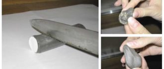
The best option for electrode wire is a 5 kg coil. Its outer diameter is 200 mm, inner diameter is 50 mm. For the axis of rotation, you can use a PVC sewer pipe. Its outer diameter is 50 mm.
Burner
A homemade semi-automatic machine must be equipped with a burner. You can do it yourself, but it’s better to buy a ready-made kit, which includes:
- Burner with a set of tips of different diameters.
- Supply hose.
- Euro connector.
A normal burner can be purchased for 2-3 thousand rubles. Moreover, the device is homemade, so you don’t have to chase expensive brands.
What to look for when choosing a kit:
- what welding current is the torch designed for;
- the length and rigidity of the hose - the main task of the hose is to ensure free flow of wire to the torch. If it is soft, any bend will slow down the movement;
- springs near the connector and burner - they prevent the hose from breaking.
Feeder
The electrode wire must be fed continuously and evenly - then the welding will be of high quality. The feed speed must be adjusted. There are three options for how to make the device:
- Buy a fully assembled mechanism. Expensive, but fast.
- Buy feed reels only.
- Do it all yourself.
If the third option is chosen, you will need:
- two bearings, guide roller, tension spring;
- motor for feeding wire - a motor from windshield wipers will do;
- metal plate for fastening the mechanism.
One pressure bearing - it must be adjustable, the second serves as a support for the roller. Manufacturing principle:
- holes are made on the plate for the motor shaft and for mounting bearings;
- the motor is fixed behind the plate;
- a guide roller is put on the shaft;
- bearings are fixed at the top and bottom;
It is best to place the bearings on metal strips - one edge is bolted to the main plate, and a spring with an adjusting bolt is connected to the other.
The completed mechanism is placed in the housing so that the rollers are located in line with the burner connector, i.e., so that the wire does not break. A rigid tube must be installed in front of the rollers to align the wire.
Implementation of the electrical part
For this you will need:
- two automotive relays;
- diode;
- PWM regulator for the engine;
- capacitor with transistor;
- idle solenoid valve - for supplying gas to the burner. Any VAZ model will do, for example from a V8;
- wires.
The wire and gas supply control circuit is quite simple and is implemented as follows:
- when you press the button on the burner, relay No. 1 and relay No. 2 are activated;
- relay No. 1 turns on the gas supply valve;
- relay No. 2 works in tandem with a capacitor and turns on the wire feed with a delay;
- wire pulling is done with an additional button, bypassing the gas supply relay;
- To remove self-induction from the solenoid valve, a diode is connected to it.
- It is necessary to provide for connecting the burner to the power cable from the inverter. To do this, next to the Euro connector, you can install a quick-release connector and connect it to the burner.
The semi-automatic device has the following operating sequence:
- The gas supply is turned on.
- The wire feed starts with a slight delay.
This sequence is necessary so that the wire immediately enters the protective environment. If you make a semi-automatic machine without delay, the wire will stick. To implement it, you will need a capacitor and a transistor through which the motor control relay is connected. Operating principle:
- voltage is applied to the capacitor;
- it is charging;
- current is supplied to the transistor;
- the relay turns on.
The capacitance of the capacitor must be selected so that the delay is approximately 0.5 seconds - this is enough to fill the weld pool.
After assembly, the mechanism must be tested, and the manufacturing process can be seen on video.
Inverter conversion
To make a semi-automatic machine from a conventional inverter with your own hands, you will have to slightly alter its electrical part. If you connect an MMA inverter to the assembled case, you will be able to cook. But at the same time, the quality of welding will be far from that of a factory semi-automatic machine.
It's all about the current-voltage characteristics - current-voltage characteristics. The electric arc inverter produces a falling characteristic - the output voltage floats. And for the correct operation of a semi-automatic device, a strict characteristic is required - the device maintains a constant voltage at the output.
Therefore, in order to use your inverter as a current source, you need to change its current-voltage characteristic (volt-ampere characteristic). For this you will need:
- toggle switch, wires;
- variable resistor and two constant;
Getting a hard characteristic on an inverter is quite simple. To do this, you need to place a voltage divider in front of the shunt that controls the welding current. Fixed resistors are used for the divider. Now you can get the required millivolts, which will be proportional to the output voltage, not the current. There is only one drawback to this scheme - the arc is too rigid. To soften it, you can use a variable resistor, which is connected to the divider and the output of the shunt.
The advantage of this approach is that the arc stiffness can be adjusted - this setting is only available in professional semi-automatic machines. And the toggle switch switches the inverter between MMA and MIG modes.
Thus, converting an MMA inverter into a semi-automatic device, although not an easy task, is quite feasible. The result is a device that is not inferior to the factory ones in its characteristics. But at the same time it is much cheaper. The cost of such an alteration is 4-5 thousand rubles.
Source: https://svarkalegko.com/oborudovanie/kak-sdelat-poluavtomat-iz-invertora.html
Homemade semi-automatic welding machine with your own hands: diagram, how to use it correctly
A semi-automatic welding machine can be homemade, made from an inverter. Let’s say right away that making a semi-automatic welding machine from an inverter with your own hands is not easy, but not impossible. Anyone who is planning to make a semi-automatic machine with their own hands from an inverter should study the principle of its operation, watch, if necessary, a video or photo on this topic, and prepare the necessary components and equipment.
To work you will need:
- An inverter machine that can generate a welding current of 150 A.
- Feeding mechanism for a semi-automatic machine (welding wire).
- Burner.
- The hose through which the welding wire passes.
- Hose for supplying shielding gas to the welding zone.
- Reel of welding wire (will require some modifications).
- Electronic control unit.
Semi-automatic welding circuit diagram
Particular attention is paid to redesigning the feeder, which feeds wire into the welding zone, which moves along a flexible hose. To obtain a high-quality, neat weld, the wire feed speed through the flexible hose and the speed of its melting must be consistent.
When semi-automatic welding, wire of different diameters and from different materials is used, so it should be possible to regulate the speed of its feed. This is done by the feeding mechanism.
The most common wire diameters in our case: 0.8; 1; 1.2 and 1.6 mm. Before welding, the wire is wound onto reels, which are attachments secured with simple fasteners. The wire is fed automatically during the welding process, which significantly reduces the time of the technological operation and increases efficiency.
The main element of the electronic circuit of the control unit is a microcontroller responsible for stabilizing and regulating the welding current. The current parameters and the ability to regulate them depend on this element.
Remaking an inverter transformer
You can make a semi-automatic welding machine with your own hands by remaking the inverter transformer. To bring the characteristics of the inverter transformer in accordance with the required ones, it is wrapped with a copper strip wrapped with thermal paper. Ordinary thick wire is not used for these purposes, because it will get very hot.
The secondary winding is also being redone . To do this you need:
- Wind a winding of three layers of sheet metal, each of which is insulated with fluoroplastic tape.
- The ends of the windings are soldered to each other to increase current conductivity.
The design of the inverter used for inclusion in a semi-automatic device must include a fan to cool the device.
When making a semi-automatic machine from an inverter, first de-energize the equipment. To prevent the device from overheating, place its input and output rectifiers, as well as power switches on radiators.
After completing the above procedures, connect the power section to the control unit and connect it to the power supply. When the power connection indicator lights up, connect an oscilloscope to the inverter outputs. Using an oscilloscope, look for electrical pulses at 40-50 kHz. There should be 1.5 µs between the formation of pulses, and this is regulated by changing the voltage supplied to the input.
Oscillogram of welding current and voltage: at reverse polarity - on the left, at normal polarity - on the right
Check that the pulses that are reflected on the oscilloscope screen are rectangular and their leading edge is no more than 500 ns. If the parameters being checked are as they should be, connect the inverter to the mains.
The current supplied from the output must be at least 120A. If this value is less, it is likely that a voltage not exceeding 100 V is flowing into the equipment wires. In this case, the equipment is tested by varying the current (plus the voltage on the capacitor is constantly monitored). The temperature inside the device is also constantly monitored.
After testing, check the device under load: connect a rheostat with a resistance of at least 0.5 Ohm to the welding wires. It must withstand a current of 60 A. The current supplied to the welding torch is controlled by an ammeter. If it does not correspond to the required value, the resistance value is selected empirically.
Usage
After starting the device, the inverter indicator should display a current value of 120 A. If the value is different, something was done incorrectly. Eights may appear on the indicator.
Most often this occurs due to insufficient voltage in the welding wires. It is better to immediately determine the cause of this malfunction and eliminate it. If everything is correct, the indicator will correctly show the current strength, which is controlled by special buttons.
The current adjustment interval provided by the inverters lies in the range of 20–160 A.
In order for the semi-automatic device to serve for a long time, it is recommended to constantly monitor the temperature conditions of the inverter. For control purposes, two buttons are pressed simultaneously, and then the temperature of the hottest inverter radiator is displayed on the indicator. Normal operating temperature is no more than 75 ° C.
If there is more, in addition to the information that is displayed on the indicator, the inverter will make an intermittent sound, which should immediately alert you. In this case (or when the temperature sensor is shorted), the electronic circuit will automatically reduce the operating current to 20A, and the sound signal will sound until the equipment returns to normal. An error code (Err), which is displayed on the inverter indicator, may also indicate a malfunction of the equipment.
When is a semi-automatic welding machine used?
Semiautomatic is recommended to be used when precise, neat connections of steel parts are needed. Using such equipment, thin metal is welded, which is important, for example, when repairing car bodies. Qualified specialists or a training video will help you learn how to operate the device.
Source: https://tokar.guru/svarka/poluavtomat-svarochnyy-svoimi-rukami-shema.html
We make a semi-automatic welding machine from an inverter
Modern manufacturers produce a large number of welding inverters with a wide range of functions. These include semi-automatic machines operating in MIG/MAG mode, which means supplying inert or active gas and welding wire to the joint of the workpieces.
Unfortunately, the cost of such units exceeds the financial capabilities of many people. Therefore, the desire to convert welding inverters into semi-automatic machines is finding more and more followers, since it is possible to save significant amounts.
We will consider the possibility of such a modification and the necessary details for this.
The main differences between a welding inverter and a semi-automatic machine
Often, the master is faced with the question of choosing between an inverter or a semi-automatic welding machine, the difference between which lies in the quality of the seam and the types of metals being welded. If a conventional inverter allows welding in AC/DC mode, with piece electrodes of different thicknesses, then semi-automatic welding machines connect parts with welding wire.
It is fed into the melting zone at a controlled speed and has different thicknesses, and to ensure the best result, the process takes place in an inert or active gas (MIG/MAG) environment.
Semi-automatic machines allow you to weld all kinds of metals of various thicknesses, while the size of the electrode does not change and the working area is always at the same distance from the person.
The semi-automatic welding machine contains an inverter, but also contains an adjustable wire feed unit and a special hose with a torch and cylinder. This equipment can weld aluminum alloys, carbon and stainless steel, cast iron and titanium, and with special wire - brass and galvanized metal.
When assembling a semi-automatic machine from an inverter with your own hands, you will need the following factory or home-made components:
- welding machine with AC/DC modes, outputting adjustable currents from 10 to 200A, with variable pulse voltage;
- a torch with the ability to supply welding wire and the corresponding gas to the place of welding work;
- a hose reinforced with a spring to ensure uninterrupted supply of wire and gas;
- gas cylinder with reducer and pressure gauge;
- reverse welding cable with clamp;
- Control block;
- reliable, adjustable unit for feeding welding wire of various thicknesses.
These elements can be purchased factory-made, and some of them can be made by hand. The inverter, burner and gas cylinder must be purchased from the manufacturer, since the technical requirements for these components require a quality certificate.
Construction of a torch and hose for a semi-automatic welding machine
Using a semi-automatic welding machine, we can increase the speed of work by more than two and a half or three times, since there is no need for multiple passes of the seam, its cleaning and replacement of piece electrodes. To increase productivity, it is necessary to ensure an uninterrupted supply of inert gas, voltage and wire to the weld pool. For this purpose, use a device consisting of the following components:
- a cylinder with a reducer, adjusted to a flow rate of 6-10 liters per minute and equipped with a gas supply hose;
- Euro-sleeve, hose-cable 3 m long, through which current, wire and gas are supplied, as well as a control signal;
- a torch with a tip, a power button and a nozzle for different wire diameters, equipped with a nozzle for inert or active gas.
Creating a Euro-sleeve yourself is quite difficult; you need to take into account that the diameter of the wire used ranges from 0.8 to 1.6 mm, and it must pass through the welding hose without any hindrance. For this purpose, the channel is equipped with a spring, using a Teflon coating; in addition, a gas supply passes through the same hose.
The control signal from the burner button also passes through the cable, and at the end there is usually a multi-pin Euro connector, through which all components are turned on and supplied.
The complex design of the torch and its operation at high temperatures implies the presence of refractory nozzles with holes for different diameters of welding wire.
Gas is supplied through the torch, as well as the wire feeding mechanism to the weld pool is turned on. It consists of the following elements:
- handle with control button;
- burner;
- gas nozzle;
- calibrated current-carrying tip.
It is important to ensure the reliability of electrical contacts and tight connections of gas hoses.
Feeder design
The process of assembling a semi-automatic welding machine with your own hands can take place either using a factory feeding device or its home-made version. In order to make it yourself, you need to understand what the factory product consists of, namely:
- on the front panel there is a Euro connector for connecting a welding sleeve;
- on the back of the case there is a toggle switch for turning on the power supply and connectors for connecting to the inverter and gas supply system;
- inside the case there is a power supply unit for the feeding device;
- feed unit with a fixed, freely rotating spool of wire;
- Next there is a clamping, adjustable feeding device connected through a gearbox to the electric motor shaft;
- circuit for adjusting the speed of the electric motor, ensuring the forward movement of the welding wire at a given speed;
- a solenoid that provides or shuts off the gas supply to the burner through the valve;
- gas supply tubes to the solenoid and Euro connector;
- power cable supplying welding current to the wire feed unit;
- a scheme for coordinating gas supply and wire movement with a delay of 1-2 seconds, preventing burnout or sticking of the wire when working in an aggressive oxygen environment;
- cables connecting the inverter and the feeder.
It is important that the feed system be mounted on electrically insulating material, since the welding wire is energized and acts as an electrode, and electrical contact with the equipment frame must be prevented.
It is necessary to ensure effective adjustable pressure on the feed roller, since the wire has a different cross-section, depending on the thickness of the workpieces being welded.
It is important to ensure the ratio of all nodes involved in ensuring the translational movement of the wire in order to avoid kinks that impede smooth feeding at the required speed. The material of the gas supply hose must be heat-resistant, and the connections must be provided with reliable clamps.
It won’t be difficult to choose a power supply with suitable parameters that will ensure the operation of the electric motor and electronic circuits of the feeder.
Step-by-step assembly of a semi-automatic device
When converting inverters into semi-automatic machines, it is necessary to take into account some circumstances. When purchasing an inverter, it is desirable that it supports MMA+MIG/MAG mode. The device will not cost much more, but when switching to the MIG mode, it will provide a stable current-voltage characteristic at the output, which will ensure smooth operation of the semiautomatic device at a current below 40 A.
Otherwise, you will have to make changes to the electronic circuit of the inverter and use PWM to stabilize the voltage parameters. This can be done provided that you understand electronics and are good at using a soldering iron.
It is important to match the reference and output voltages by installing a divider and selecting the component values for supplying a signal to the controller inputs.
Further steps for assembling a semi-automatic machine from a welding inverter, a feeder and a Euro-sleeve with a torch are as follows:
- switch the inverter to MIG mode and connect it to the feeder with a power and control cable;
- connect a gas cylinder through a reducer and a pressure gauge to the supply device, and also adjust the flow of 6-10 liters per minute depending on the gas composition and welding conditions;
- install and secure the wire reel into the feed unit;
- using the speed control circuit, set the required feed speed of the welding wire and make sure that it moves unhindered;
- connect the burner to the euro-sleeve, which, in turn, connects to the feeder;
- turn on the inverter and feeding equipment and make sure there is a delay of 1-2 seconds between the arrival of gas and the movement of the wire.
Correct selection of wire thickness, composition of inert or active gas, as well as correct operation of radio-electronic components will ensure high speed and quality of welding work.
Let's sum it up
We looked at some ways to convert welding inverters into semi-automatic machines with our own hands. This is a fairly complex task, but upon close examination it is not particularly difficult. It is only important to ensure reliable operation of the elements and electrical safety. The main thing is that these efforts and temporary losses will provide very significant savings.
Source: https://electrod.biz/apparat/modifications/delaem-svarochnyiy-poluavtomat-iz-invertora.html
How to make a semi-automatic welding machine with your own hands from an inverter?
Reading time: 7 minutes
A semi-automatic machine is not just a tool for many craftsmen. This is a complete assistant in the household and at work. Every craftsman may need it: from a summer resident to a car enthusiast. After all, the semi-automatic machine is excellent for welding all types of metals with virtually no restrictions on thickness and composition. At the same time, welding can be both professional and amateur.
Semi-automatic devices appeared on mass market not long ago. Old-school welders remember how they used to weld metal using large, bulky transformers. However, with the development of technological progress, engineers managed to design a compact and convenient semi-automatic machine. At the beginning of the 20th century, it supplanted the devices of the previous generation and won the respect of most welders around the world.
A modern semi-automatic machine is capable of performing various types of welding work. This can be MMA welding, MIG/MAG welding, as well as TIG welding. All this is possible thanks to the “stuffing” of the semi-automatic device. The device is based on a standard inverter. This means that, in theory, you can assemble a semi-automatic machine yourself. Of course, using the inverter as a “donor”. This article will cover everything: the basics of how a semi-automatic machine works, and how to convert a welding inverter into a semi-automatic machine.
Semi-automatic device
The structure of a semi-automatic machine is the first thing you need to study if you want to assemble your own machine.
A standard semi-automatic machine consists of two parts (or two blocks): power and feed. The feed part is simply a feed device for semi-automatic welding. But, let's take a closer look at the semi-automatic device.
The power part, also known as the power unit, is essentially an inverter. The inverter acts as a current source. Everything is simple here. But the feeding part is a separate, plug-in feeding mechanism. The feed mechanism is used to feed the wire. The wire is sold in reels and the reel is inserted directly into the feeder. Its end exits through the burner nozzle.
Of course, you don't have to use a feed mechanism to perform semi-automatic welding. The wire can also be fed manually. But this is extremely inconvenient, and in this case the whole essence of semi-automatic technology is lost.
That's all the components. This, of course, is not enough to make a semi-automatic welding machine on your own. You will also have to buy additional parts, but they depend on the type of inverter you have and the method by which you will convert it into a semi-automatic machine. Don’t forget about the components (burner, hose, correctly selected nozzle, etc.).
Principle of operation
The operating principle of the semi-automatic device is simple. It will be clear even to a beginner, so study this information carefully. It will be useful for assembling a homemade device.
So, it all starts with feeding the torch into the welding zone. The torch combines two devices: from its nozzle it supplies protective gas and wire simultaneously. The welder regulates the amount of gas manually, but the wire is fed in a semi-automatic mode (hence the name “semi-automatic”). That is why the welder always has only one hand occupied during the process. The one holding the burner.
As we have already said, gas is supplied to the welding zone simultaneously with the wire. An electric discharge is formed in the mixture of gases between the end of the wire and the metal surface, due to which the workpiece and the wire itself melt. Molten metal is mixed with molten wire. Next, you can form the seam.
In this case, wire is necessary and without it welding is simply impossible. Gas is also needed; it protects the weld pool from oxygen coming from outside. But if you do not have the opportunity to use gas, you can take a special cored wire and cook only with it.
Semiautomatic from inverter
There are several ways to make a working semi-automatic device from an inverter. We will list the most interesting, in our opinion. You can implement them at home with basic knowledge of electrical engineering.
Method No. 1
To make an inverter semi-automatic welding machine with your own hands, you will need a “donor”. Without it, it’s simply not possible to make a semi-automatic machine. As a “donor”, take not the weakest inverter for MMA welding. It must be operational and perform normal welding operations without any problems.
You need to change the current-voltage characteristics of the inverter you have chosen so that it can operate in semi-automatic welding mode. You can use a PWM controller for this. However, this option is very labor-intensive and is not suitable for those who are not strong in electrical engineering.
Therefore, in order to assemble a semi-automatic welding machine from an inverter with your own hands, we recommend making a choke. A choke from a fluorescent lamp is suitable for this. And after the throttle you need to take the feedback voltage. Watch the video below, which explains the essence of this method in detail. There is also a clear diagram in the video.
Method No. 2
The second method is extremely simple and is suitable for those who have a certain inverter welding. The fact is that there are inverters on sale that can switch to a mode with a rigid change in the current-voltage characteristic. If you are the owner of just such an inverter, then you can only be happy for yourself. To turn such a device into a semi-automatic machine, you just need to purchase an external feed mechanism.
The mechanism must include all the necessary cables and connectors. You just need to easily connect the welding wire feeder to the welding inverter and you can start welding. We can assume that in this case the feed mechanism works as an attachment to the inverter for semi-automatic welding. Watch the video below, where the author talks about his inverter, to which he connected the feeder.
Method No. 3
The last method of converting from a welding inverter into a semi-automatic machine with your own hands will require some knowledge and skills. In this case, you will also need a donor inverter. Please note that not every device will work. You need an inverter with ZX-7 layout. It must have a shunt at the output, and there must be a current transformer at the “primary”. It’s even better if the device doesn’t have any additional functions like hot start or arc force.
You also need to change the current-voltage characteristics, and also set the current rise setting. Further actions directly depend on the circuit of your inverter. So don’t be lazy to find topics on various forums dedicated to converting an inverter into a semi-automatic machine. Watch the video below with a test of such a homemade device.
Source: https://svarkaed.ru/oborudovanie-dlya-svarki/apparaty/samodelnye/kak-sdelat-svarochnyj-poluavtomat-svoimi-rukami-iz-invertora.html
Do-it-yourself semi-automatic inverter
To make a semi-automatic machine from an inverter with your own hands, you need to make a number of significant changes that will make its functions and operations as similar as possible to machines for semi-automatic welding.
Here you will need to add a wire feed mechanism, which is the main difference, as well as a supply of protective gas for the wire. All this complicates the operation of the equipment, but for professional use it turns out to be completely justified.
Buying a new semi-automatic machine if you have an old inverter is not always economically profitable, so it makes sense to try to do everything yourself.
Tools and materials for creating a semi-automatic machine from an inverter
To make a semi-automatic welding machine from an inverter with your own hands, you will need:
- burner;
- constant voltage source;
- gas and wire supply hose;
- wire feeder.
Remaking the welding inverter transformer
Making a homemade semi-automatic machine from a welding inverter begins with the preparatory process. First you need to redo the electrical part of the device. As a rule, it is obtained in two buildings. One contains a welding inverter, and the second contains a feed mechanism with consumables.
Theoretically, a semi-automatic machine can be made without a second body, but here it is necessary to take into account the ease of operation. Practicality also matters, since all parts must be clean. Otherwise, there will be problems with wire feeding.
A system unit is often used as a suitable box. Its dimensions are well suited for such purposes; the required holes can be drilled in it, etc.
To calculate space in any drawer, you need to first cut out mock-ups of the internal elements to compare.
In homemade versions, wire spools with a maximum weight of up to 5 kg are most often used. The outer diameter of such a device is 20 cm, and the inner diameter is 5 cm. Any light pipe with a diameter of 5 cm will work as an axis of rotation. PVC pipes are excellent.
Consumables feed mechanism
An important part of converting a welding inverter into a semi-automatic machine with your own hands is the torch. Naturally, there are options for making it yourself, but it is better to purchase a new kit, which includes:
- multi-tip burner;
- gas supply hose;
- reliable standard connectors for connection.
Important!
When choosing, you should find out what current the device is designed for, whether it comes with springs, and what the parameters of the hose are.
Burners for semi-automatic machines
Another serious point in the question “How to make a semi-automatic machine from an inverter?” is the feeding mechanism. It is necessary to ensure a uniform and constant wire feed. The quality of work depends on this. It is desirable that the feed speed can be adjusted. You can make the mechanism yourself, buy a ready-made one, or purchase feed reels.
Source: https://svarkaipayka.ru/oborudovanie/svarochnie-apparaty/poluavtomat-iz-invertora-svoimi-rukami.html
Converting an inverter into a semi-automatic circuit from Gosha
> Repair > How to make a semi-automatic machine from an inverter with your own hands
A good owner must have a semi-automatic welding machine, especially owners of cars and private property. You can always do small jobs with it yourself.
If you need to weld a machine part, make a greenhouse, or create some kind of metal structure, then such a device will become an indispensable assistant in your personal household. Here a dilemma arises: buy or make it yourself. If you have an inverter, it’s easier to do it yourself.
It will cost much less than buying in a retail chain. True, you will need at least basic knowledge of the basics of electronics, the availability of the necessary tools and desire.
Making a semi-automatic machine from an inverter with your own hands
Structure
It is not difficult to convert an inverter into a semi-automatic welding machine for welding thin steel (low-alloy and corrosion-resistant) and aluminum alloys with your own hands. You just need to have a good understanding of the intricacies of the work ahead and delve into the nuances of manufacturing. An inverter is a device that serves to lower the electrical voltage to the required level to power the welding arc.
The essence of the semi-automatic welding process in a protective gas environment is as follows. The electrode wire is fed at a constant speed into the arc burning zone. Shielding gas is supplied to the same area. Most often - carbon dioxide. This guarantees a high-quality weld, which is not inferior in strength to the metal being joined, while there are no slags in the joint, since the weld pool is protected from the negative influence of air components (oxygen and nitrogen) by shielding gas.
The kit of such a semi-automatic device should include the following elements:
- current source;
- welding process control unit;
- wire feed mechanism;
- shielding gas supply hose;
- carbon dioxide cylinder;
- torch gun:
- spool of wire.
Welding station design
Semi-automatic Sanych
To make the transformer, Sanych used 4 cores from TS-720. The primary winding was wound with copper wire Ø 1.2 mm (number of turns 180+25+25+25+25), for the secondary winding I used an 8 mm2 busbar (number of turns 35+35). The rectifier was assembled using a full-wave circuit. For the switch I chose a paired biscuit. I installed the diodes on the radiator so that they would not overheat during operation.
The capacitor was placed in a device with a capacity of 30,000 microfarads. The filter choke was made on a core from TS-180. The power part is put into operation using a TKD511-DOD contactor. The power transformer is installed TS-40, rewound to a voltage of 15V. The roller of the broaching mechanism in this semi-automatic machine has a Ø 26 mm. It has a guide groove 1 mm deep and 0.5 mm wide. The regulator circuit operates at a voltage of 6V.
It is sufficient to ensure optimal feeding of the welding wire.
How other craftsmen improved it, you can read messages on various forums dedicated to this issue and delve into the nuances of manufacturing.
Inverter setup
How to make an antenna for digital TV with your own hands
To ensure high-quality operation of a semiautomatic device with small dimensions, it is best to use toroidal type transformers. They have the highest efficiency.
The transformer for operation of the inverter is prepared as follows: it must be wrapped with a copper strip (40 mm wide, 30 mm thick), protected with thermal paper, of the required length. The secondary winding is made of 3 layers of sheet metal, insulated from each other. To do this, you can use fluoroplastic tape. The ends of the secondary winding at the output must be soldered. In order for such a transformer to operate smoothly and not overheat, it is necessary to install a fan.
Transformer winding diagram
Work on setting up the inverter begins with de-energizing the power section. Rectifiers (input and output) and power switches must have radiators for cooling.
Where the radiator is located, which heats up the most during operation, it is necessary to provide a temperature sensor (its readings during operation should not exceed 75 0C). After these changes, the power section is connected to the control unit. When switched on.
The network indicator should light up. You need to check the pulses using an oscilloscope. They should be rectangular.
Their repetition rate must be in the range of 40 ÷ 50 kHz, and they must have a time interval of 1.5 μs (the time is adjusted by changing the input voltage). The indicator should show at least 120A. It would not be superfluous to check the device under load. This is done by inserting a 0.5 ohm load rheostat into the welding leads. It must withstand a current of 60A. This is checked using a voltmeter.
A properly assembled inverter when performing welding work makes it possible to regulate the current in a wide range: from 20 to 160A, and the choice of operating current depends on the metal that needs to be welded.
To make an inverter with your own hands, you can take a computer unit, which must be in working condition. The body needs to be strengthened by adding stiffeners. An electronic part is mounted in it, made according to Sanych’s scheme.
Wire feeding
How to assemble a touch switch with your own hands
Most often, such home-made semi-automatic machines provide the possibility of feeding welding wire Ø 0.8; 1.0; 1.2 and 1.6 mm. Its feeding speed must be adjusted. The feeding mechanism together with the welding torch can be purchased at a retail chain.
If you wish and have the necessary parts, you can do it yourself. Savvy innovators use an electric motor from car wipers, 2 bearings, 2 plates and a Ø 25 mm roller for this. The roller is installed on the motor shaft. Bearings are attached to the plates. They press themselves against the roller. Compression is carried out using a spring.
The wire passes along special guides between the bearings and the roller and is pulled.
All components of the mechanism are installed on a plate with a thickness of at least 8-10 mm, made of textolite, and the wire should come out in the place where the connector connecting to the welding sleeve is installed. A coil with the required Ø and grade of wire is also installed here.
Pulling mechanism assembly
Balloon
To supply shielding gas to the combustion zone of the welding arc, it is best to purchase a standard type cylinder. If you use carbon dioxide as a shielding gas, you can use a fire extinguisher cylinder by removing the speaker from it. It must be remembered that it requires a special adapter, which is needed to install the reducer, since the threads on the cylinder do not match the threads on the neck of the fire extinguisher.
Semi-automatic with your own hands.
You can learn about the layout, assembly, and testing of a homemade semi-automatic machine from this video.
A do-it-yourself inverter semi-automatic welding machine has undoubted advantages:
- cheaper than store-bought counterparts;
- compact dimensions;
- the ability to weld thin metal even in hard-to-reach places;
- will become the pride of the person who created it with his own hands.
Source: https://respect-kovka.com/peredelka-invertora-v-poluavtomat-shema-ot-goshi/
Homemade semi-automatic welding machine 2 in 1
I always wanted to have my own welding machine, and even thought about buying one, but there was winter ahead (more time), and I decided to make it myself. A semi-automatic machine was needed more, but arc welding would not hurt, so I decided to make a 2in1 p-semi-automatic and arc welding from one transformer.
Manufacturing
For arc welding, I only had to wind up the required number of turns of wire on the transformer so that the transformer would produce 45 volts, and that’s all.
Manufacturing of magnetic circuit
Now let's start in order. First, I started making a magnetic core; I made it from two magnetic cores from LATRs.
One was cut to the required size.
Winding unwinding device
I unwound both and, using a simple device, wound them into one.
Then I impregnate the magnetic circuit with epoxy glue so that the transformer does not hum and there is no short circuit of the plates.
After this, we wrap the magnetic circuit with cardboard.
Then I wrapped everything with cotton tape and masking tape.
For more information about assembling a toroidal magnetic circuit, see the video below:
Winding the primary and secondary windings
The next stage is winding the primary and secondary windings. I wound according to this scheme based on my magnetic circuit cross-section
(calculated individually for each transformer).
The primary winding is wound with copper wire with a cross-section of 2 mm2 (I have it made up of several cores). For the convenience of winding under the magnetic core, I made a stand that is attached to the table.
We wind the wire on a shuttle - it’s much easier to wind it this way.
I impregnate each layer with varnish and wrap it with cotton fabric or electrical tape on top.
The wire cross-section on the secondary winding is 16 mm2.
I talked more about winding in the video below:
I also made a video about the results of the intermediate tests:
Manufacturing of the broaching mechanism
The next step is to make a broaching mechanism. As a motor, I used a motor from a VAZ 2101 windshield wiper.
I bought the feed roller ready-made, but it can also be turned by a turner.
In order to have less load on the engine axis, I installed two bearings that are connected to each other and the pressure to the roller is adjusted with a screw.
Welding sleeve
2.5 meter long hose rated at 160 amps.
Choke winding
Next we wind the throttle, which is an integral part of the semi-automatic device. It serves to smooth out current pulses, and without it the semi-automatic device will not work fully. It is wound on a TC 250 transformer from the TV.
But TS 270 is better. You need to wind as much as you can until the window is filled with at least 20 mm2 of wire. There must be a non-magnetic gap between the horseshoes of the transformer and it is initially set at 2 mm (textolite plate), but the best result is achieved experimentally by increasing or decreasing the gap in resulting in the best possible weld.
Control board and circuit
Also, one of the main components of the semi-automatic device is the control board; I made it according to this scheme.
The printed circuit board file (DipTrace program project) can be downloaded from the Svapka.ru website via the link: http://svapka.ru/down/svapka20smd.dip
There is also an alternative engine speed control scheme.
Instead of a gas valve, I used a VAZ 2108 windshield washer valve.
200 amp power diodes on radiators.
Ground wire.
Primary voltage switch.
Thyristor T-161-160 ampere.
Case manufacturing
And finally, the final stage is the manufacture of the case, the arrangement of all elements and assembly according to the diagram.
Well, and most importantly, we’ll see how it all works in the final video.
If you have any questions, ask, I will answer everyone.
Thank you for your attention!
Source: https://www.freeseller.ru/5399-samodelnyy-svarochnyy-poluavtomat-2-v-1.html
Making a semi-automatic welding machine with your own hands
Using a semi-automatic welding machine makes it easier to work with metals. This technique can easily join different alloys. You can make a semi-automatic welding machine with your own hands from an existing inverter, and a home-made unit will be distinguished by its versatility and functionality in use, allowing you to save on the purchase of industrial equipment.
Design Features
A design feature of a semi-automatic welding machine is the constant supply of molten wire into the welding zone, which is used instead of metal electrodes.
Wire feeding is carried out automatically, with the ability to change the speed of movement of flexible electrodes.
The welding wire used will ensure constant contact of the surfaces being connected; such material, in comparison with standard electrodes, has less resistance, which improves the quality of the connection.
Semi-automatic welding is distinguished by its versatility, which allows using this technology to weld metals of various characteristics, including stainless steel, non-ferrous alloys, aluminum and others. Mastering the correct semi-automatic welding technique is not difficult.
Homemade devices are easy to use, so they can be recommended to ordinary homeowners.
Depending on their type, semi-automatic machines may have an additional nozzle for supplying gas, and the metals are joined in a protective environment, which makes it possible to eliminate the subsequent formation of corrosion in the weld.
Welding inverters offered in stores today are distinguished by their versatility, and many of them have a two-in-one function. With low power and dimensions, a two-in-one inverter and semi-automatic welding machine can work with refractory metals and thick metal workpieces.
Advantages and disadvantages of homemade equipment
Many homeowners, who often have to perform welding work, decide to manufacture such equipment themselves. The advantages of homemade semi-automatic machines from an inverter include the following:
- Simplicity and reliability of technology.
- Functionality of the device.
- High power allows you to weld refractory metals.
- Affordable cost of the components used.
- Complete safety of working with the equipment.
- Ease of operation of the equipment.
Among the disadvantages of this technology and the equipment itself, one can note the high cost of semi-automatic machines, which, with characteristics similar to the inverter, can have a price two to three times higher. It is not surprising that many homeowners decide to make the equipment themselves, which allows them to significantly reduce costs without losing the quality of the device.
Source: https://pochini.guru/sovety-mastera/izgotovlenie-svarochnogo-poluavtomata
Homemade semi-automatic welding machine from an inverter: how to assemble it yourself, instructions, diagrams
With experience, many professionals come to the conclusion that a semi-automatic welding machine is much more than a tool. This is a universal assistant in household welding both at the dacha and when repairing a car.
It does not limit you in the choice of material for welding and will be useful not only for the master, but also for the beginner.
Mass production of semi-automatic machines began just a few years ago. Old-school welders used to connect structures with huge transformers.
But technological progress is moving forward and has made it possible to create a portable and lightweight semi-automatic machine. Having appeared on the market, it quickly showed the world its advantages and sent the old models to rest.
Today, they have access to a variety of welding types: MMA, MAG/MIG, and TIG.
This was achieved because there is a regular inverter inside the device. It follows from this that a working semi-automatic machine can be made at home, using an inverter as a basis. At the end of this article, you will have all the tips and knowledge you need to do this.
How does a semi-automatic machine work?
Before you start working with any equipment, the first thing you need to do is familiarize yourself with its design.
Each semi-automatic machine contains two blocks: power and feed.
The power unit is represented by an inverter that supplies current. The feed unit is a separate device that is connected to feed the wire. A coil of wire is secured in the feed block, and the end comes out near the burner nozzle.
But for our purposes it is not really needed. You can do the wire feeding yourself, but this will slow down the work process and will be extremely inconvenient.
We have described to you the main elements of the device, but this is not enough. You will also need to order special parts needed for a specific type of inverter, as well as accessories (burner, sleeve, nozzle, etc.).
Workflow Features
Mastering semi-automatic welding is not as difficult as it might seem. After reading this article, even an inexperienced welder can handle it.
Let's start with how the burner works. The torch consists of two mechanisms that simultaneously provide the supply of shielding gas and wire.
The first can be adjusted independently, but the second is carried out in semi-automatic mode (this is how the corresponding name appeared). Because of this, the welder uses only the hand that holds the torch.
Let's return to the supply of shielding gas to the welding point. A mixture of gases surrounds the end of the wire and the top layer of material, and in this environment an electric discharge occurs that melts the workpiece with the wire.
The softened metal is mixed with the wire, and after that the weld can be made.
When welding, you cannot do without wire. Gas is also necessary because it prevents oxygen from entering the bath. But even in the absence of gas, you can use special cored wire.
Homemade semi-automatic
There are different approaches to creating a homemade semi-automatic welding machine from an inverter, but we will focus on the most practical and interesting ones.
By following these instructions, any beginner with basic knowledge of electrical engineering can do this at home.
Method No. 1
You can construct a semi-automatic welding device at home using a handy inverter. It is impossible to do without it.
A medium power inverter is suitable for MMA welding. It is important that it is in working order and can perform simple operations.
Next, you need to change the current-voltage characteristics (volt-ampere characteristics) to operate in semi-automatic mode. This is where a PWM controller comes in handy. Note that this approach is the most difficult and only experienced welders can handle it.
It is necessary to make a choke from a fluorescent lamp and switch the voltage to feedback. In the video below you can find out all the details and diagrams of this method.
Method No. 2
This method of assembling a homemade semiautomatic welding machine is very simple and can be mastered by almost every person who has dealt with inverter welding. Some inverter models can be switched to a mode with a rigid change in the current-voltage characteristic.
If you have such a device on hand, then you can easily make a semi-automatic machine out of it. All that remains is to order an external supply unit.
It is important to have the appropriate wires on hand. You just need to connect the feed unit to the inverter and you are ready to cook. In this case, the supply block acts as an addition. The video below demonstrates the features of this method.
Method No. 3
The last method of assembling a homemade semi-automatic welding machine will not seem so simple, because here you will need certain knowledge and skills. As in the previous case, you will also need a donor inverter.
You won’t be able to get by with just any device, because what is required is the assembly of the ZX-7 with a shunt at the output. The absence of arc forcing and hot start will only be beneficial.
Don't forget about the current-voltage characteristics, they also need to be changed. Next, adjust the current rise. Depending on the inverter assembly, further steps may vary from source to source.
We recommend that you read more information on special forums. In the video below you can take a look at the operation of a homemade semi-automatic machine.
Bottom line
This is all the information you need to make a homemade semi-automatic welding machine from an inverter. This tool will come in handy in cases where you don’t have a factory model at hand.
By remodeling it, you will not only save money, but also gain new electrical skills. This semi-automatic machine does not require careful maintenance and can be stored either in the basement or in the garage.
In addition, repairing the instrument will not take you much time and effort, since you perfectly understand what parts it consists of.
It is important to remember that a homemade device will not be your ideal assistant. It is not recommended to use it for a long time.
In many aspects and characteristics it will be much inferior to the factory models, and you will be taking a risk if you rebuild it in the field. For serious welding work, it will be better to purchase a tool in a store.
In this article, we were not able to cover all the nuances of self-assembly of a semi-automatic machine. But this information will be quite enough for you. It is possible to assemble it at home, but this process is quite difficult and not the most profitable.
Homemade equipment will almost always perform worse than factory equipment. Consider this before you decide to take such a step. We wish you good luck in your work!
Source: https://prosvarku.info/apparaty/samodelnyj-svarochnyj-poluavtomat
Step-by-step instructions for making a semi-automatic welding machine with your own hands
An automatic welding machine is a special device designed for welding joints of metal products. The devices are manufactured with different parameters, but regardless of the type, the most important design element is the inverter mechanism.
For stable operation, it is required that the inverter has high quality, the required functionality, and is safe for the user.
Devices from well-known brands are expensive, while Chinese ones do not inspire confidence among consumers. Therefore, some welders prefer to make semi-automatic welding machines with their own hands using simple diagrams and manufacturing technology.
What will you need?
The homemade apparatus includes:
- a mechanism that controls the characteristics of the output current;
- power unit;
- burners;
- clamping devices;
- rubber sleeves;
- cart.
To assemble a semi-automatic welding device with your own hands you will need:
- device for additive wire;
- a flexible hose for supplying powder or gas under the required pressure to the welded joint area;
- coil;
- electronic unit for controlling the device.
Created plan
Before producing a semi-automatic welding machine with your own hands, an action plan is drawn up at each stage of work. This will increase the speed of installation and determine the required devices and products.
First you need to decide on the circuit diagram of the semiautomatic device.
Next, you need to think about what device or device to use as a housing for compact installation of electronic components and mechanisms.
Then you need to analyze the dimensions of the parts required for assembly and consider their placement inside the case. For example, if you have time, you can make three-dimensional prototypes of parts and place them in a space of suitable volume according to the accepted scheme of a semi-automatic welding machine.
Preparing the transformer
The transformer consists of a pair of coils with a winding of insulated wire, one winding is primary, the other is secondary.
To remake an inverter device, only the secondary coil is changed . It needs to be redone to reduce the voltage and increase the current. To do this, the existing wrap is removed and a new one is wound from the insulated cable.
The number and thickness of turns can be determined using specialized online services.
Upon completion of laying the wires, the windings are covered with insulating material.
Source: https://svarka.guru/oborudovanie/vidy-apparatov/poshagovaya-instrukciya-po-izgotovleniju-poluavtomata-svoimi-rukami.html
Do-it-yourself semi-automatic welding machine from Sanych, diagram
A semi-automatic welding machine can be homemade, made from an inverter. Let’s say right away that making a semi-automatic welding machine from an inverter with your own hands is not easy, but not impossible. Anyone who is planning to make a semi-automatic machine with their own hands from an inverter should study the principle of its operation, watch, if necessary, a video or photo on this topic, and prepare the necessary components and equipment.
How to convert an inverter into a semi-automatic machine
To work you will need:
- An inverter machine that can generate a welding current of 150 A.
- Feeding mechanism for a semi-automatic machine (welding wire).
- Burner.
- The hose through which the welding wire passes.
- Hose for supplying shielding gas to the welding zone.
- Reel of welding wire (will require some modifications).
- Electronic control unit.
Semi-automatic welding circuit diagram
Particular attention is paid to redesigning the feeder, which feeds wire into the welding zone, which moves along a flexible hose. To obtain a high-quality, neat weld, the wire feed speed through the flexible hose and the speed of its melting must be consistent.
When semi-automatic welding, wire of different diameters and from different materials is used, so it should be possible to regulate the speed of its feed. This is done by the feeding mechanism.
The most common wire diameters in our case: 0.8; 1; 1.2 and 1.6 mm. Before welding, the wire is wound onto reels, which are attachments secured with simple fasteners. The wire is fed automatically during the welding process, which significantly reduces the time of the technological operation and increases efficiency.
The main element of the electronic circuit of the control unit is a microcontroller responsible for stabilizing and regulating the welding current. The current parameters and the ability to regulate them depend on this element.
Settings
When making a semi-automatic machine from an inverter, first de-energize the equipment. To prevent the device from overheating, place its input and output rectifiers, as well as power switches on radiators.
After completing the above procedures, connect the power section to the control unit and connect it to the power supply. When the power connection indicator lights up, connect an oscilloscope to the inverter outputs. Using an oscilloscope, look for electrical pulses at 40-50 kHz. There should be 1.5 µs between the formation of pulses, and this is regulated by changing the voltage supplied to the input.
Oscillogram of welding current and voltage: at reverse polarity - on the left, at normal polarity - on the right
Check that the pulses that are reflected on the oscilloscope screen are rectangular and their leading edge is no more than 500 ns. If the parameters being checked are as they should be, connect the inverter to the mains.
The current supplied from the output must be at least 120A. If this value is less, it is likely that a voltage not exceeding 100 V is flowing into the equipment wires. In this case, the equipment is tested by varying the current (plus the voltage on the capacitor is constantly monitored). The temperature inside the device is also constantly monitored.
After testing, check the device under load: connect a rheostat with a resistance of at least 0.5 Ohm to the welding wires. It must withstand a current of 60 A. The current supplied to the welding torch is controlled by an ammeter. If it does not correspond to the required value, the resistance value is selected empirically.
Checking for correct operation
In order for the semi-automatic device to serve for a long time, it is recommended to constantly monitor the temperature conditions of the inverter. For control purposes, two buttons are pressed simultaneously, and then the temperature of the hottest inverter radiator is displayed on the indicator. Normal operating temperature is no more than 75 ° C.
If there is more, in addition to the information that is displayed on the indicator, the inverter will make an intermittent sound, which should immediately alert you. In this case (or when the temperature sensor is shorted), the electronic circuit will automatically reduce the operating current to 20A, and the sound signal will sound until the equipment returns to normal. An error code (Err), which is displayed on the inverter indicator, may also indicate a malfunction of the equipment.
Semi-automatic welding from an inverter
To convert an inverter into a semi-automatic welding machine, you will need three main modules. Electric, providing current from the inverter and welding mode, a mechanism for supplying wire and a torch with a nozzle.
The burner creates a gaseous environment in the form of a cloud of protective inert gas that prevents oxidation of the molten metal. For this, a carbon dioxide cylinder is used, which is connected to the device using a hose and an inlet fitting.
If you use filler material with a special coating that forms a protective environment, you can do without a cylinder. This method is common among craftsmen.
Source: https://crast.ru/instrumenty/svarochnyj-poluavtomat-svoimi-rukami-ot-sanycha
Homemade semi-automatic welding machine
The capabilities of a semi-automatic welding machine are significantly higher than those of a machine designed for manual arc welding. A semi-automatic machine can weld much thinner metal.
The use of a special welding wire allows you to work with non-ferrous metals, and the use of shielding gas provides a weld of higher quality. Considering these circumstances, the desire to add such a device to your home workshop is understandable.
General information
If you can’t buy a semi-automatic welding machine, you can try to assemble it yourself. It must be said right away that this task is not the easiest, and only those who have certain skills in working with electrical devices, have already repaired something, and understand circuits, can assemble a homemade semi-automatic welding machine. For those who decide to do this, we can recommend several possible assembly options.
Before planning work on creating a semi-automatic welding machine, you should study the principles of semi-automatic welding, as well as the design and operation of the device intended for this.
Semi-automatic welding machines are devices that carry out direct current electric arc welding using a special welding wire as an electrode in a shielding gas environment.
The wire is wound on a rotating spool and is automatically fed to the welding site, passing through a feed mechanism. The circuit of a semi-automatic welding machine can contain both an inverter and a transformer current source.
The welder lights the arc with his own hands and makes the seam, which is why the work is called semi-automatic. An analogue of the electrode holder in a semi-automatic welding machine is a torch that has a pistol grip with a button for turning on the wire feed.
The wire is fed through a thin channel passing inside the rubberized sleeve connecting the semiautomatic device to the burner. The channel for supplying gas during welding is located in the same sleeve and ends with a nozzle at the end of the torch.
Before lighting the arc, by turning on the wire feed, you need to ensure that it extends beyond the edge of the torch by 10 - 15 mm.
Then the gas supply is turned on and the welding process begins. The wire and gas feed speed is adjusted by hand and by rotating the heads located on the front panel of the semi-automatic welding machine.
From a welding transformer
If you have an old welding transformer at your disposal, it can serve as the basis for assembling a semi-automatic machine with your own hands.
If the old device has a rectifier and successfully cooks with direct current, nothing else needs to be done in this part. If it is just a transformer for AC welding, it should be modified.
Diode bridge
In order to obtain a source of direct current for welding, the transformer must be equipped with a diode bridge and a filter. The diode assembly rectifies the secondary voltage, the filter smoothes out ripples, maintaining stable arc burning.
The rectified voltage of a single-phase transformer has the form of a sinusoid, the lower half-waves of which are reflected symmetrically to the abscissa axis and moved to the upper quadrants of the coordinate system.
Essentially, this is a voltage pulsating at a frequency of 100 hertz, reaching zero twice per period. Using such a voltage for welding as a constant voltage leads to an unstable arc. To eliminate this phenomenon, a filter is required to smooth out voltage dips.
Filter
The filter consists of a choke connected in series to the welding circuit and a capacitor connected in parallel. This combination of inductance and capacitance is called an L-shaped filter, because in the diagram, the elements connected in this way form the letter L.
The capacitor for the future semiautomatic device needs an electrolytic, polar, capacity of 10,000 microfarads, the more the better. The capacitor voltage must be at least 100 volts to have a good margin. You can solder several capacitors in parallel, and the capacitance is summed up.
Throttle
To wind the inductor with your own hands, you need to find an old transformer of suitable dimensions. A power transformer from old tube color TVs with a power of at least 250 watts is well suited for this purpose.
The transformer has two coils on an oval closed core consisting of two halves. The transformer is disassembled, the coils are removed, and the old wire is removed from them.
For winding, a suitable flat copper busbar is selected. On each coil, instead of the removed wire, two layers of turns of a copper bus are wound by hand. The coil should have 15 - 20 turns.
After this, the steel core is assembled, the coils are put in place, and a 1.5 mm thick textolite gasket is inserted between the halves of the core. The coils are connected in series.
Broach
You can build a wire drawing mechanism for a semi-automatic machine with your own hands, using small bearings and an electric motor from car wipers.
But it is better to buy a ready-made one; it is sold as a spare part for semi-automatic welding machines. You will also have to buy a torch and a hose through which wire and gas will be supplied.
From an inverter for manual welding
If the workshop has a welding inverter for manual welding, the problem with the power source for the semi-automatic machine can be considered solved. Based on a manual welding machine, you can make a semi-automatic inverter with your own hands.
In order not to disassemble a working inverter converter, you can proceed as follows. All additional components necessary for the operation of the semi-automatic welding machine can be located in a separate housing.
Providing power to the broach and valve
Since the electric motor of the wire drawing mechanism and the valve that shuts off the gas are powered by a constant voltage of 12 volts, you will have to install a small transformer with a rectifier to provide this power.
To switch the motor and valve, it is better to install intermediate automotive relays at 12 volts. The wire drawing is turned on using a key on the torch, held by hand, to open and close the gas supply valve; a toggle switch is installed on the front panel.
This arrangement will allow you to use the inverter both for manual welding and as a power source for a semi-automatic welding machine. The costs of manufacturing a homemade semi-automatic device are low, but the benefits from it will be tangible.
Source: https://svaring.com/welding/apparaty/svarochnyj-poluavtomat-svoimi-rukami