Methods for inspection of welded vessels
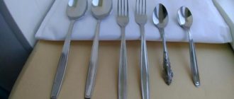
5.1.1. The geometric dimensions and shape of surfaces must be measured using means that provide an error of no more than 30% of the established manufacturing tolerance.
The overall dimensions of the vessels should be determined by summing the sizes of the assembly units and parts included in them.
5.1.2. Quality control of surfaces for the absence of caps, sunsets, delaminations, rough marks, cracks that reduce quality and impair presentation must be carried out by visual inspection.
5.1.3. Mandatory verification of the presence, content, location of marks on welds and markings on the finished vessel (independently supplied assembly units and parts) must be carried out by visual inspection.
5.1.4. Quality control of welded joints should be carried out using the following methods:
- a) visual inspection and measurement;
- b) mechanical tests;
- c) testing for resistance to intergranular corrosion;
- d) metallographic studies;
- e) steeloscoping;
- f) ultrasonic flaw detection;
- g) radiography;
- h) color or magnetic particle flaw detection;
- i) other methods (acoustic emission, luminescent control, determination of ferrite phase content, etc.) provided for in the project.
5.1.5. Final quality control of welded joints of vessels subjected to heat treatment must be carried out after heat treatment.
For welded joints of a vessel made of low-alloy manganese, manganese-silicon steels or two-layer steels with a main layer of these steels, subjected to normalization or hardening with tempering during the manufacturing process, mechanical tests and metallographic studies may be carried out before final heat treatment (high tempering). In this case, the obtained positive results of mechanical tests should be considered final.
(Changed edition, Amendment No. 2).
5.1.6. Control of completeness, preservation, painting, packaging must be carried out by comparing the volume and quality of work performed with the requirements of this standard and technical specifications.
5.1.7. The manufacturer of oversized vessels transported in parts must carry out control assembly.
Instead of assembly, it is allowed to carry out a control check of the dimensions of the joined parts, provided that the manufacturer guarantees the assembly of the vessel.
5.1.8. During the manufacturing process of assembly units and parts, it is necessary to check:
- compliance of the condition and quality of welded assembly units and parts and welding materials with the requirements of standards (technical conditions) and the project;
- compliance of the quality of edge preparation and assembly for welding with the requirements of standards and the project;
- compliance with the welding and heat treatment process developed in accordance with the requirements of the standards and the project.
5.2. Visual inspection and measurement of welds
5.2.1. Visual inspection and measurement of welds must be carried out after cleaning the seams and adjacent surfaces of the base metal from slag, splashes and other contaminants.
5.2.2. All welds are subject to mandatory visual inspection and measurement in accordance with GOST 3242 to identify external defects that are not permissible in accordance with the requirements of this standard.
Visual inspection and measurement should be carried out in accessible places on both sides along the entire length of the seam.
5.3. Mechanical tests
5.3.1. Butt welded joints must be subjected to mechanical tests. Mechanical tests must be carried out on control butt welded joints to the extent indicated in Table. 18.
Table 18. Number of samples from each control butt welded joint
Type of test Groups of vessels Number of samples Note| Tensile at +20°C | 1-5 | Two samples of type XII, XIII, XIV or XV according to GOST 6996 | Tensile testing of individual samples of welded pipe joints can be replaced by tensile testing of entire joints with the force removed |
| Bend at +20 °C | 1-5 | Two samples of type XXVII, XXVIII according to GOST 6996 | Testing of welded pipe samples with an internal diameter of up to 100 mm and a wall thickness of up to 12 mm can be replaced by a flattening test in accordance with GOST 6996 (samples of type XXIX, XXX) |
| Impact strength KCU (metal thickness 12 mm or more) at +20 °C | 1-5 from steels prone to thermal effects (12МХ, 12ХМ, 15Х5М, 10Х2М1А-А, etc.) | Three samples of type VI according to GOST 6996 with a notch along the axis of the seam | The impact bending test of the heat-affected zone is carried out on welded joints made by electroslag welding without subsequent normalization, as well as if there are requirements in the technical conditions or design |
| 1-3 at pressure more than 5 MPa (50 kgf/cm2) 1-2 at temperature above 450° 0 | |||
| Impact strength KCU (metal thickness 12 mm or more) at an operating temperature below -20 ° C, equal to the minimum negative operating temperature of the vessel | 1-3, 5 at operating temperature below -20 °C | Three samples of type VI according to GOST 6996 with a notch along the axis of the seam | Test at operating temperature. The impact bending test of the heat-affected zone is carried out on welded joints made by electroslag welding without subsequent normalization, as well as if there are requirements in the technical conditions or design |
| Measuring the hardness of weld metal at a temperature of +20 °C | 1-4 in accordance with the requirement of clause 5.3.2. | At least at three points along the length of each section of the welded joint in accordance with GOST 9012, GOST 9013, GOST 18661, GOST 6996 |
Notes: 1. The length of the controlled section should be taken as the length of the welded connection made by one welder using the technology provided for in the technical documentation for this type of assembly unit or part.
2. It is allowed not to carry out mechanical tests of welded samples for vessels of group 5b if the manufacturer guarantees the quality of the welds.
(Changed edition, Amendment No. 2).
3. Impact bending testing of welded joints of vessels operating at temperatures not lower than -20 °C should be carried out at room temperature.
4. When testing samples with a thickness of more than 50 mm for bending, it is allowed to bring the thickness of the samples to 50 mm by gouging or milling control plates. Samples made of two-layer steels should be milled or planed from the side of the main layer and bent with the main layer outward. Sample type XXVII according to GOST 6996, mandrel diameter - two sample thicknesses.
It is allowed to carry out bending tests on samples with their preliminary thinning to a thickness of at least 30 mm.
5. The impact bending test of welded joints made of two-layer steels should be carried out on samples made according to Fig. 19.
6. Tensile, bending, impact bending tests of a welded joint with a thickness of 50 mm or more must be carried out in accordance with the requirements of RD 26-11-08.
(Changed edition, Amendment No. 2).
7. It is allowed not to test for impact bending at negative temperatures welded joints made of steels of austenitic and austenitic-ferritic classes, made with welding materials specified in mandatory appendices 12, 14, 15, 16.
Rice. 19. Sample for bending test of welded joints made of two-layer steels
5.3.2. Hardness measurement should be carried out on the weld metal of welded joints of vessels (pressure parts) made of steel grades 12МХ, 12ХМ, 15ХМ, 20Х2М, 1Х2М1, 10Х2ГНМ, 10Х2МFA-А, 10Х2М1А-А, 15Х5М and the weld metal of the corrosion-resistant layer of the above grades in welded joints from double-layer steels. Hardness must be checked at least at three points across the welded joint according to RD 26-11-08.
It is allowed to measure the hardness of the weld metal on control samples if it is impossible to carry it out on the finished vessel (part).
(Changed edition, Amendment No. 2).
5.3.3. If unsatisfactory results are obtained for any type of mechanical test, it is allowed to repeat the test on a double number of samples cut from the same control welded joint for the type of mechanical test that gave unsatisfactory results.
If, during repeated testing, unsatisfactory results are obtained on at least one sample, the welded joint is considered unsuitable.
5.4. Intergranular corrosion resistance test
5.4.1. Testing of a welded joint for resistance to intergranular corrosion must be carried out for vessels (assembly units, parts) made of steels of austenitic, ferritic, austenitic-ferritic classes and two-layer steel with a corrosion-resistant layer of austenitic and ferritic steels if there is such a requirement in the technical conditions or design .
The need to test resistance against intergranular corrosion of welded joints of internal devices operating without pressure must be indicated in the design.
5.4.2. The shape, dimensions and number of samples must comply with GOST 6032.
(Changed edition, Amendment No. 2).
5.4.3. The test for resistance to intercrystalline corrosion should be carried out in accordance with GOST 6032 or the corresponding regulatory and technical documentation. The test method must be specified in the design.
The weld metal and heat-affected zone must be resistant to intergranular corrosion.
5.4.4. If unsatisfactory results are obtained, repeated testing is allowed on a double number of samples cut from the same control welded joint.
If, during repeated testing, unsatisfactory results are obtained on at least one sample, the welded joint is considered unsuitable.
5.5. Metallographic studies
5.5.1. Butt welded joints that determine the strength of vessels should be subjected to metallographic examination:
- 1, 2, 3 groups, operating under pressure more than 5 MPa (50 kgf/cm2) or at temperatures below -40 ° C;
- 1, 2 groups operating at temperatures above 450 °C;
- from steels prone to thermal effects (grades 12МХ, 12ХМ, 15Х5М, etc.), from austenitic steels without a ferrite phase (grades 06ХН28МДТ, 08Х17Н16МЗТ, etc.) and from two-layer steels.
It is allowed not to carry out metallographic examinations of butt welds of assembly units and parts operating at temperatures below -40 °C, with a thickness of no more than 20 mm made of steel grades 12Х18Н10Т and 08Х18Н10Т.
5.5.2. Metallographic macro- and micro-examinations must be carried out in accordance with RD 24.200.04 on one sample from each control welded joint.
5.5.3. The quality of the control welded joint during metallographic studies must comply with the requirements of paragraphs. 3.11.3 and 3.11.4.
Source: https://gazovik-proekt.ru/cat/articles2/sosudy_apparaty/metody_kontroly/
What is steeloscopy of welds?
Among the non-destructive methods of weld inspection, metal styloscopy is the most “ancient”. It was introduced in the 30s of the last century. It is used to check the homogeneity of connections of high-pressure vessels, boilers, pipelines, and loaded welding metal structures.
Steelscoping quickly determines harmful impurities, although the accuracy of the result largely depends on the vigilance of the operator, the method is reliable.
The procedure for styloscopy of welded seams is regulated by GOST 7122-81; it is indicated in the regulatory and technical documentation for many types of work: in the production of pipelines, welded process tanks, and support structures.
What is steeloscopy
Firstly, this is an express method of the chemical composition of welded joints, the presence of carbon, sulfur, phosphorus, and other alloying elements in the metal.
In the language of textbooks, steeloscopy of seams is a non-destructive testing method based on comparison of the spectral lines of evaporating melt vapors with reference photographs. It is difficult to determine the concentration of components from the spectrum.
The operator makes an assessment by eye. The result of steeloscopy is always subjective. But serious accidents can be avoided after testing welds.
Application area
Identification of components that reduce the quality of welds is the main goal of steeloscopy. The metal is capable of becoming saturated with gases during the welding process; the elements burn out at a temperature exceeding the melting point. The analysis reveals violations in the manufacturing technology of welded vessels and pipelines. Under pressure, a defective connection may burst.
https://www.youtube.com/watch?v=ZbnEIr5ITFc
Steeloscopy of the weld metal is carried out to determine the chemical composition. Phosphorus and carbon are determined in the spark mode, the remaining components are determined in the arc spectrum. Quality control is necessary in the production of cast products. Steelscoping determines the steel grade during metal acceptance to a warehouse or when dismantling scrap. Portable models can be used in any conditions; before assembling or repairing metal structures, if necessary, the chemical composition of the workpieces is checked.
Advantages and disadvantages
Steelscoping is popular because:
- ease of use;
- the ability to analyze metal and welds on site, without transportation to the laboratory; quick results;
- duration of use of consumables;
- the integrity of the samples and tested welds is not compromised;
- no major capital investment required.
Source: https://svarkaprosto.ru/tehnologii/stiloskopirovanie-svarnyh-shvov
Steelscoping of welds - what is it?
When joining metals by welding, almost imperceptible defects may appear inside the seam or on its surface due to the high temperature of the arc. Any of them negatively affects the strength of the final product, since the smallest cracks can lead to depressurization.
What is steeloscopy of welds, what is the essence of this method
There are several methods, the use of which allows you to identify minor seam defects before use. One of the most accessible is steeloscopy, which is based on spectral analysis. The method is aimed at identifying the amount of alloying impurities in the weld. In other words, it is possible to determine the chemical composition of the metal at the junction.
GOSTs used for work
There are several documents that clearly regulate all the nuances associated with the steeloscopy process:
Areas of use
Any products made of alloy steel are subject to control (in addition to standard impurities, specific elements are introduced into its composition to achieve the desired strength, durability and other indicators. Such elements include chromium, nitrogen, nickel, etc.).
The chemical composition of the seam is checked for any containers and pipes that will subsequently be exposed to high pressure and chemically aggressive environments.
The method is relevant for those industries where strict adherence to the composition of alloys is important. It is not used in small private enterprises whose metal structures do not require a high level of control.
Technology
The verification procedure is simple, but requires special equipment and certain operator skills.
Equipment used
Steeloscope is equipment that allows steeloscopy. There are two types: stationary (used in the laboratory) and portable (suitable for production).
Regardless of size, they are very similar and have a number of identical nodes.
The main element of a steeloscope is an electrode, the main function of which is to ignite an arc on the product . Most often it is made of steel, tungsten or copper and installed on the head of the device.
Using a grinding wheel (or less often a lathe), the end of the electrode must be sharpened for it to work correctly.
The specialist must have with him a whole set of replaceable electrodes, because measurements can be made only once, after which they need another correction.
The second main element of the steeloscope is a generator connected to the body . Thanks to it, current is supplied to the rod itself, which, in turn, excites the arc. Light emanates from it, which, passing through metal vapor, penetrates the gap. Its width, depending on the type of device, ranges from 0.01 to 0.02 mm.
One of the key elements of a steeloscope is a series of lenses, thanks to which the exact chemical composition of impurities can be determined.
The three-lens system, or photometric wedge, has different focal lengths. It first receives a beam of light onto two prisms, which is then reflected and directed into the eyepiece lens. Such a system is usually replaceable and has different degrees of magnification.
Procedure
Algorithm of actions:
- The surface of the seam is cleaned , removing slag, dust and metal particles from it.
- The sample is placed near the electrode.
- Light up the discharge.
- The operator notes exactly what color of the spectrum the discharge had (from red to violet).
- All possible areas are marked in a special steeloscope atlas.
- Thanks to the tables in the atlas, you can determine the correspondence between the exact concentration of impurities and the brightness of the glow.
- The experiment should be carried out several times to obtain a more accurate result.
Advantages and disadvantages of the method
The method is widespread due to a number of positive aspects:
- The method is absolutely safe and to use it you only need to follow electrical safety rules.
- The integrity of the product is maintained after analysis . The operation of the equipment being diagnosed does not need to be stopped.
- The price of the procedure is relatively low.
- The portable steeloscope can easily be placed next to the work surface due to its small dimensions.
Despite the fact that the method is simple and safe, its use is difficult due to some disadvantages:
- Difficulty in preparing and training specialists . On average it takes from 2 to 6 months.
- When steeloscoping, it is impossible to detect the presence of carbon and sulfur , which contribute to the destruction of the seam.
- The glow of the arc has a negative effect on the retina of the eyes . It can be reduced by using special safety glasses.
- This method can only be used in rooms equipped with ventilation , otherwise the gases can harm the operator’s respiratory system.
Source: https://rem-serv.com/stiloskopirovanie-svarnyh-shvov-chto-eto-takoe/
Steelscoping – Quality
Contact us by phone 249-48-68 or Submit an application
One type of quality control of the chemical composition of pipeline seams and components of various equipment is called steeloscopy.
According to the current acceptance rules, seams must necessarily comply with regulatory and technical documentation (NTD). The main task of the specialists who carry it out is visual control, which consists of comparing brightness.
They are obtained by analyzing the brightness of spectral lines with reference photographs.
Steelscoping is performed using specialized instruments called steeloscopes. There are 2 types of such equipment:
- Using portable devices, they perform rapid analysis in warehouses and field conditions. In addition, they are used to control large structures. Total weight can vary from 2 to 5 kilograms.
- If steeloscopy needs to be carried out in a laboratory, stationary devices are used. They are much more sensitive than their analogues and can operate for a longer period of time, but the parameters of the nodes studied are extremely limited.
Physical basis of the method
The steeloscopy process is based on the glow of metal vapors in a low-voltage spark. A similar arc discharge is formed using electrodes. The first of them is, in fact, a sample that is to be studied, and the second is a permanent instrument electrode, which has the form of a steel rod or a copper disk.
When the arc burns, the substance is transferred from one electrode to another and hot vapors are formed between them. Spectral lines directly depend on the type of metal used. Steeloscopes are equipped with special eyepieces, in which, in fact, you can observe the process of decomposition of radiation into spectral lines.
As a result of the data obtained during the research, spectrograms are compiled.
Parameters and design of units
- The selection of the optimal spectral range is of utmost importance (the fact is that the devices of the previous generation have a rather narrow spectrum, which does not allow them to identify all the impurities of the weld);
- the ability to destroy is also of no small importance;
- when choosing a device, pay attention to whether it has an option that will allow you to enlarge the eyepiece;
- The luminous intensity parameter is of no small importance (in essence, it is the difference between the brightness of the vapor glow and the image entering the device);
- Finding the focus of the equipment lens and its eyepiece also affects the veracity of the readings.
The design of steeloscopes includes two main elements. The first of them is a “gun”, which is equipped with optics and a burning unit equipped with a specialized electrode. The second is a generator. The higher its power, the longer the device will work. The generator is equipped with a power transformer, an ammeter, an inductive coil, resistance and condensation units, several switches, indicating devices and connectors for connecting cables. In the latest generation model, manufacturers connect USB cables.
It is no coincidence that styloscopic analysis is in high demand. Thanks to steeloscopes, it is possible to obtain objective results on chemical analysis in the shortest possible time. The seams and products remain intact, which means the costs of such research are reduced significantly. To operate the devices, no special knowledge in using such equipment is required.
Source: https://qvality.ru/uslugi/mehanicheskie-ispytaniya/stiloskopirovanie/
Steelscoping: non-destructive testing
Steelscoping is a method that helps to quickly determine the chemical composition of the weld metal for compliance with the standards of regulatory and technical documentation. This will help determine the presence of carbon, sulfur, phosphorus, chromium, nickel, etc.
The general procedure for performing the non-destructive testing procedure is established by the provisions of Rostechnadzor Order No. 490 dated November 21, 2016. This regulatory document defines the general conditions for the use of methods that are safe for analysis, and also determines the rules for the implementation of relevant work.
The list of basic non-destructive testing methods and typical technologies for their use are described in the interstate standard GOST 18353-79. This standard contains about ten different positions. It also states that this list may be supplemented by other methods for verifying the integrity of objects.
In this case, the rules and conditions for their application must be established by federal norms and regulations approved by order of Rostechnadzor.
Special guidance documents
The technology for testing the integrity of an object using non-destructive testing methods can vary significantly depending on the following factors:
- the material from which the object is made;
- size of the analyzed object;
- the presence of welded joints, moving parts and other features;
- scope of application of the equipment or part;
- other factors.
Depending on the above reasons, the inspection of an object can be carried out using one or another non-destructive testing technology. For the purpose of unifying the procedure within various fields of activity, special guidance documents are being developed.
Non-destructive testing by steeloscopy: application of the method
Thus, steeloscopy is regulated by the provisions of RD 26.260.15-2001. According to this regulatory document, steeloscopy is a non-destructive testing method that is used to control the quality of the following elements:
- system elements and vessels made of high-alloy types of steel. The requirement for the mandatory nature of steeloscopy applies to those that are under pressure;
- welds connecting these elements. Steelscoping is carried out in places and volumes established by the manufacturer.
To use this method, special measuring instruments are required - styloscopes. Steelscoping is a non-destructive testing method that involves a qualitative spectral analysis of the relevant objects. During its execution, the metal is checked for compliance with current requirements.
Source: https://www.CentrAttek.ru/info/nerazrushajushhij-kontrol-stiloskopirovanie/
What is steeloscopy of welds? For what purpose?
Steelscoping of seams of welded joints is one of the types of quality control. Despite its low accuracy, it is widely used in the production of vessels and pipelines for the purpose of quickly determining alloying components and some harmful impurities.
The procedure for carrying out work, the scope and location of analysis are regulated by industry guidelines and state standards.
Steelscoping of welds - what is it?
Steelscoping is an express method for assessing the chemical composition of weld metal for compliance with the requirements of NTD (normative and technical documentation). It is based on visual control, which consists of comparing the brightness of the obtained spectral lines with reference photographs.
This method was first introduced into practice in the 30s. XX century and is still widely used in industry.
Using steeloscopy, you can determine the presence of the following substances in steels and non-ferrous alloys:
- alloying additives (chrome, nickel, tungsten, molybdenum, titanium and others);
- carbon;
- sulfur;
- phosphorus.
This control method belongs to the qualitative and semi-quantitative (subjective) type of analysis, that is, it is used in cases where there are no high requirements for measurement accuracy.
Steelscoping is also carried out as the first step in assessing the quality of welds of critical joints. If its results do not meet the requirements of the scientific and technical documentation, then other types of research are carried out, on the basis of which a final conclusion is made about the suitability of the compound.
Normative documents
The need for steeloscopy of welded joints is determined by design and project documentation, technical standards established by the organization that manufactures metal structures and equipment.
There are also requirements for such control in relation to the following objects:
Source: https://plavitmetall.ru/oborudovanie/stiloskopirovanie-svarnyx-shvov.html
Control of welds in hard-to-reach places. Control methods
I work as a welder at a construction site.
Little work experience. I mainly weld pipes for plumbing systems. Quite often I join pipes when the seam is almost close to the wall. You have to get creative and bend the electrode. But that's not so bad. You can’t stick your head between the pipe and the wall to see how it’s brewed. Please tell me, experienced welders, how do you get out of this situation? Thanks in advance!
There is such difficulty in the work of welders. Especially when installing pipelines on submarines. That's where they first began to use a female round mirror to control welded joints in hard-to-reach places.
But, firstly, it is not always possible to put your hand with a mirror between the wall and the part, and secondly, sometimes you need to cook with a mirror, but you don’t have enough hands! In one there is a holder with an electrode, in the other there is a welding mask.
This is where an inspection mirror comes to the rescue, which can be pre-fixed in a convenient position, and through it you can observe and control the welding process. And your hands are free, and the zone is accessible!
Weld inspection methods
Responsible structures are monitored for defects. But it is not always possible to distinguish defects with the naked eye or with some magnification. This happens due to the fact that they can merge with the general relief due to their small size or simply be located inside the seam without coming to the surface.
Therefore, various non-destructive testing methods (NDT) are used, designed to reveal all existing flaws.
The quality of the weld affects the performance of parts and structures: their strength properties deteriorate, which can lead to destruction during operation. Systems experiencing constant or variable pressure may leak due to micropores, microcracks, etc.
This is why more time, attention and expense are devoted to the inspection operation than to the welding itself.
Visual control
Despite the fact that it is among the most ineffective and imperfect methods, it is nevertheless the simplest and most widespread. They control the width of the seam and its leg, if we are talking about a corner connection, the main dimensions; measure radial runouts, leads (warping). They also look for the absence of pores, shrinkage cavities, cracks, lack of fusion, undercuts, and in the case of soldering, also unsoldered joints (read “Common Weld Seam Defects”).
The seam must be uniform, clean, without visible defects. If something is discovered that does not meet your criteria or the requirements of the technical or design documentation, this can always be corrected by welding the problem areas while final machining has not yet been carried out.
Leak test
If the design of the assembly allows for quality control of the seam for tightness, this can be done in several ways:
1. Kerosene has the ability to penetrate into the smallest pores and cracks. For example, if you have welded the bottom to a cylinder, pour a little kerosene into it; due to the capillary effect, even the presence of defects invisible to the eye will become obvious - the kerosene will seep through and appear on the outside of the glass.
2. If, in addition to tightness, the unit also needs to be checked for strength, kerosene or other working fluid is supplied with a pressure several times higher than the working one. Check the absence of liquid on the welds visually or using indicator paper.
3. The tightness can also be checked by supplying compressed air to the unit at a pressure of several atmospheres. Such a unit is immersed in distilled water and the absence of air bubbles on its surfaces is checked.
This is carried out using ultrasonic flaw detectors.
Using this method, hidden defects such as cracks, lack of penetration, slag inclusions, and blockages are determined. You can control the results of argon arc, electric, contact, electron beam, diffusion and other types of welding. The essence of the method is that ultrasound sent through a metal part using a sensor passes through it if it does not encounter obstacles. As soon as a “cavity” appears, for example, an uncooked area, the sound is reflected from it and gets back into the device, which signals a problem.
This rejection method also applies to NMC. It is based on the use of magnetic fields, to be more precise, magnetic stray fields, which are excited above the area where defects are located during local magnetization of parts. As a composition for indication, a ferromagnetic material, crushed into powder, is applied (the controlled material must also have a ferromagnetic nature).
Using MK, defects lying or extending to the surface, as well as those located under the surface, are identified.
Subsurface defects can lie at a significant depth; the intensity of the indication directly depends on the size of the defect. The larger it is, the higher the magnitude of magnetic scattering. Casting parts produced by welding (seams) are subject to defects from operation.
Cracks of various natures of formation, hairlines (air bubbles stretched into “lines” during the metal rolling process), lack of fusion and other defects with a size of 0.001 mm are detected.
MK has the following advantages:• MK devices are highly sensitive;• Simplicity of technology for checking parts of various geometric sizes and shapes;• Some elements can be controlled without removing them from the metal structure;
• High defect detection rate.
MK technological process:• Preparatory work. Parts must be clean, washed in nefras and acetone. optimal roughness Ra2.5 (see GOST 21105-87);• Magnetization;• Immersion in a bath with an indicator suspension or applying it (depending on the type of devices used: stationary, portable);
• Visual inspection of the resulting “picture” and sorting.
The second name is capillary flaw detection. The method is very reliable. It is based on the use of the property of the composition of the indicator liquid (penetrant) to penetrate into the smallest cracks, pores, scratches, which can be revealed as a result of subsequent processing.
In this way, it is possible to make visible defects that come to the surface and cannot be detected either by visual inspection with the naked eye, or even using microscopes with a high magnification of the eyepiece, due to the fact that their color is practically indistinguishable from the background of the welded part in question. .
For example, using a “capillary” you can identify a crack with a development width of less than 1 micron. After such inspection, all flaws that appear on the surface or have an opening will be tinted (“highlighted”) in red, which stands out well against the gray background of the metal .
Various tanks, pipes, and metal structures made of steel and aluminum can be tested.
However, the method requires the presence of trained personnel and special equipment, which makes it difficult to use in handicraft production.
The photo shows pores in the weld
It is carried out in accordance with GOST 7512-82 (pdf) “Non-destructive testing” and is based on the ability of various materials to absorb X-ray waves with varying degrees of intensity. For example, metal absorbs waves more than slag inclusions. Accordingly, blockages and discontinuities in the metal part will be visible in the photograph; they will be reflected in lighter areas.
In practice, the method has shown high efficiency in determining the presence of tungsten inclusions, blockages, pores and porosity, shrinkage cavities, cracks and slag, lack of fusion, etc. etc. In addition to X-ray waves, isotopes of iridium, selenium, cesium and cobalt are used. Using the method, pipelines are controlled, most often gas, oil and technological pipelines according to OST 102-51-85.
It also makes sense to check, in this way, metal structures and various production equipment.
The method is not used if:• If the direction of development of the defect does not correspond to the direction of transmission• If the sizes of cracks, discontinuities and inclusions are too small for X-ray sensitivity
Conclusion: X-ray examination is effective within its field of application; when defects are located, for example at an acute angle, their identification becomes difficult. But if you use it in combination with ultrasonic testing, the reliability of control increases.
Source: http://svarka-master.ru/kontrol-svarny-h-shvov-v-trudnodostupny-h-mestah/
Steelscoping. Determination of the chemical composition of the weld to increase the strength of the product
When joining metals by welding, almost imperceptible defects may appear inside the seam or on its surface due to the high temperature of the arc. Any of them negatively affects the strength of the final product, since the smallest cracks can lead to depressurization.
Everything about quality control of welded joints
Checking welding joints is a mandatory stage of any welding work. Thanks to careful monitoring, it is possible to identify obvious and hidden defects, which will subsequently affect the quality and durability of the entire metal structure. Of course, you can evaluate the quality of a weld with a naked eye, but this is only one of the methods.
Using visual inspection, you will not be able to detect internal cracks and pores. Therefore, it is important to know additional methods of quality control. In large industries, this work is performed by a welding supervisor, but in a small plant, this responsibility often falls on the shoulders of the welder. In this article we will tell you how to check seams and what types of quality control there are besides visual inspection.
Methods of weld quality control
There are various types and means of technical control, they all have their own advantages and disadvantages, features and nuances. But despite the differences, they are all designed to test the seams for strength and durability. The quality of welded joints largely depends on the welder and the components used, so the outcome of the inspection can be predicted. But we still recommend quality control to be sure that the products will last a long time.
The quality of welded joints can be determined by visual inspection (perhaps the most common method), ultrasonic, magnetic, capillary and radiation (radiographic) testing; welds are also monitored for permeability.
There are other methods for monitoring welds, but in this article we will list the most common and easy to use. We recommend performing operational quality control, i.e. first inspect the seam, then carry out penetrant testing and so on.
However, first things first.
Penetrant control
Methods for quality control of welded joints also include weld testing. For this, the capillary method is used. Its essence is extremely simple: for control, special liquids are used that are able to penetrate the smallest pores and cracks, called capillaries.
Using capillary operational control, you can check the quality of any metal, with any composition and shape. Often this method is used when you need to find out the presence of hidden defects that are invisible to the eye, but there is no budget, since capillary testing is very easy to use and does not require expensive equipment.
Capillary assessment of the quality of welded joints is carried out using liquids called penetrants (from the English word “penetrant”, which means “penetrating liquid”). Such liquids have low surface tension, which is why they easily penetrate small capillaries and remain visible to the eye. Essentially, penetrants fill cavities and color defects, thereby making them visible.
Now you can find many recipes for preparing penetrant, each of which will have its own properties and characteristics. You can prepare a penetrant based on water or any other organic liquid (turpentine, benzene, this also includes the quite popular test of welds with kerosene. Such penetrants are very effective and sensitive to the slightest defects. They confidently occupy one of the leading positions among quality control methods.
Checking the tightness of welded seams
Weld testing does not end with liquids. They also need to be checked for leaks. The leak testing method has many names: leak testing, bubble testing, pneumatic testing, hydro testing and many others. But regardless of the name, their essence remains the same: detection of through defects that impair the sealing performance of the welded joint.
Checking welds for leaks is performed using gases (oxygen or nitrogen) and various liquids (for example, water). The method is in many ways similar to the capillary method, but here the gas or liquid is additionally supplied under high pressure, under which they are distributed into the defective cavities and come out. This method has its own classification.
There are pneumatic and hydraulic controls, and seams can also be checked using vacuum or air blowing; these are subcategories of pneumatic control. But let's talk about everything in more detail.
Let's start with the pneumatic method of quality control of seams. It involves the use of gas or air, which is directed to the connection under pressure. In this case, the seam is lubricated with a soap solution.
There is also a type of pneumatic control called vacuum control, when an artificial vacuum is created using special equipment, a part is placed in it, and the seam is also pre-wetted with a soap solution.
In areas with through cracks, bubbles will form, indicating the location of the defect.
When preparing a soap solution, use one bar of soap per liter of water. If you have to work at low temperatures (outside in winter), then it is recommended to replace more than half of the water with alcohol. We also recommend connecting a pressure gauge, with which you can monitor the pressure indicator and be able to notice how it will drop when defects are detected. It would also be a good idea to use a safety valve to maintain safety precautions.
The simplest form of pneumatic testing is to immerse the part in water, without lubricating the seams with soapy water or using pressure. If the seam has defects, they will make themselves known when small air bubbles begin to appear from the welded joint. This method of quality control can be called field, but it is quite effective.
There is also another type of pneumatic inspection called quality control of welds and joints using ammonia. Ammonia is supplied instead of gas or air, and the seams are pre-covered with special paper tape. Ammonia passes through the seam and if there are defects, red spots appear on the tape.
The second type of leak control is hydraulic. Here pressure is created using water or oil. This is a very interesting method, since the part is kept in liquid for 5 to 15 minutes (depending on the characteristics of the metal), while the area near the seam is tapped with a hammer, the blows should be weak. If there are defects, then upon impact, liquid will begin to flow out from the intended place with a crack or other damage.
Magnetic control
The magnetic control method uses the basics of electromagnetism. The inspector or welder, using a special device, creates a magnetic field around the seam, which emits a stream of so-called electromagnetic lines. If they are distorted, then there are defects. Distortions are recorded using magnetic particle method.
With magnetic particle welding, ferrimagnetic powder is first applied to the surface of the weld, which, when the electromagnetic line is distorted, begins to accumulate at the defect site. Because of this, magnetic inspection is only available when working with ferrimagnetic metals. Aluminum, copper, steel with a high content of chromium and nickel cannot be inspected. In general, this is a very effective, but inconvenient and expensive method, so it is used only when monitoring particularly important components.
Ultrasonic testing
The ultrasound method is very interesting. It is based on the properties of ultrasound. Ultrasonic waves are easily reflected from the edges of a crack or chip, since they have different acoustic properties. In simple words, we apply ultrasound to the seam, and if it encounters a defect along its path, it is distorted and displayed in a different direction. In this case, different types of defects distort the ultrasonic wave in different ways, so that they can be easily identified.
Weld quality control using ultrasonic devices is used everywhere, since it is a fairly effective and at the same time inexpensive method. Compared to other methods (for example, magnetic or radiation), there is no need to take into account any characteristics of the metal or purchase expensive equipment. But there are also disadvantages: ultrasonic inspection of the welded joint must be carried out by a specialist, and not by an ordinary welder.
Radiation control
Radiation weld inspection (also called “radiographic inspection” and “gammagraphic weld inspection”) is a mini version of conventional x-rays.
Gamma rays penetrate the metal and all possible hidden defects are recorded on a special film. This is the most advanced and expensive method of quality control; it requires modern equipment and qualifications from the inspector or welder.
Also, excessive work with such a device can have a negative impact on human health.
Recently, digital radiography has appeared, which is performed using a computer. Here, instead of film, special reusable plates are used, which are compatible with any radiation sources. But unlike classical radiation monitoring, with the digital method, images are saved directly to a computer, they can be scaled and cropped. In the future, the developers plan to make this process automatic so that human presence is not required.
Instead of a conclusion
The welding supervisor must be very attentive to his work, since everything depends on his attentiveness. When performing quality control of welding and welded joints, record all features and defects that you can detect. Combine different weld inspection methods to get the full picture. Do not use destructive weld inspection methods that are not suitable for certain metals.
Welding and quality control of welded joints of metal structures is not an easy task, but having learned this just once, you will be able to quickly carry out control even in the field. Also, do not forget that there are safety precautions and they must be observed not only when welding, but also when inspecting seams.
Source: https://svarkaed.ru/svarka/shvy-i-soedineniya/vsyo-o-kontrole-kachestva-svarnyh-soedinenij.html
LLC NTC expert - non-destructive testing. certification of laboratories and non-destructive testing specialists, production, supply and metrology of non-destructive testing tools
Photo albums of defects detected by various NDT methods are presented in the following publications: 1. Defects detected during leak testing; 2 . Defects detected by capillary inspection; 3 . Defects detected during metallographic testing; 4 . Defects detected by magnetic particle testing; 5 . Steelscoping. Album of spectra of samples that do not comply with technical documentation.
Each photo album is compiled in the form of a presentation containing illustrations of defects with macrosections and text comments. Photo albums are intended for training and advanced training of NDT specialists and are recommended for teaching students of specialized specialties.
Photo album of characteristic defects detected during leak testing
The 16-page album contains photographs of characteristic discontinuities in welds identified by various methods of tightness control. The album is intended for training and preparation for certification of quality inspectors of base metal and welds in accordance with PNAE G-7-008-89, PNAE G-7-010-89, PNAE G-7-019-89.
album:
Photo album of characteristic defects detected during capillary inspection
The 11-page album contains photographs of characteristic discontinuities in welds identified by the capillary inspection method. The album is intended for training and preparation for certification of quality inspectors of base metal and welds in accordance with PNAE G-7-010-89, PNAE G-7-018-89, PNAE G-7-025-90.
album:
- Extended indicator (linear) traces (A)
- Extended indicator (linear) traces (B)
- Extended indicator (linear) traces (B)
- Extended indicator (linear) traces (D)
- Extended indicator (linear) traces (D)
- Round indicator marks (A)
- Round indicator marks (B)
- Round and extended (linear) indicator marks (A)
- Round and extended (linear) indicator marks (B)
Photo album of characteristic defects detected during metallographic inspection
The 13-page album contains photographs of characteristic discontinuities in welds identified by metallographic testing. The album is intended for training and preparation for certification of quality inspectors of base metal and welds in accordance with PNAE G-7-010-89, GOST 10243-75, RD 24.200.04-90.
album:
- Butt welded joint. Electroslag welding
- Butt welded joint. Submerged arc welding(s)
- Butt welded joint. Submerged arc welding (b)
- Corner butt connection. Submerged arc welding
- T-welded connection. Automatic submerged arc welding
- Fillet welded connection
- T-welded connection. Automatic submerged arc welding
- Corner welded connection. Combined welding
- Appearance of samples tested for susceptibility to intergranular corrosion using the AMU method
- Butt welded joint. Manual arc welding
- Butt welded joint. Semi-automatic welding in CO2 environment
- T-welded connection. Semi-automatic welding in Ar+CO2 environment
Photo album of characteristic defects detected during magnetic particle testing
The 20-page album contains photographs of characteristic discontinuities in welds identified by magnetic particle testing. The album is intended for training and preparation for certification of quality inspectors of base metal and welds in accordance with PNAE G-7-010-89, PNAE G-7-015-89.
album:
- Grinding cracks
- Transverse cracks
- Longitudinal cracks
- False indications
- Cracks
Steelscoping. Album of spectra of samples that do not comply with technical documentation
The album of 8 pages contains photographs of the spectra of materials that do not correspond to the chemical composition of the technical documentation, identified by the steeloscopy method. The album is intended for training and preparation for certification of quality inspectors of base metal and welds in accordance with PNAE G-7-010-89, RD EO 0505-03.
album:
- Steelscoping
- Steelscoping - a method of spectral analysis
- An example of the spectrum of steel in the orange region when determining molybdenum by the Mo2 group
- An example of the spectrum of steel in the yellow-green region when determining molybdenum by the Mo1 group
- An example of the spectrum of steel in the blue region when determining manganese by the Mn1 group
- An example of the spectrum of steel in the greenish-blue region when determining chromium using the Cr6 group
- An example of the spectrum of steel in the blue region when determining titanium by the Ti1 group
- An example of the spectrum of steel in the green region when determining tungsten by group W1
Source: http://www.ntcexpert.ru/component/content/article?id=733:fotoalbomy-defektov
Methods for quality control of welding seams
The quality of welding work and welded joints greatly influences the strength of structures or the tightness of tanks. Failure of welds to meet the specified characteristics leads to structural failures with catastrophic consequences, the same applies to systems operating with vessels and pipelines under pressure.
Therefore, after welding work, the finished product is subjected to testing and inspection to detect defects in welded joints.
All welding quality control procedures are defined by GOST or governing documents. They also indicate acceptable error limits. After the tests, a report and protocols with the measurement results are drawn up.
Verification methods
Quality control of welding work performed in production can be destructive or non-destructive. The first methods are used selectively. One or more products from a large batch, or part of a metal product in a building structure, is checked.
It is tested on various parameters using a specific test report. But mainly they use special devices or materials to check the quality of welded joints without destroying the structure.
The main methods of non-destructive welding quality control are:
- visual;
- capillary;
- permeability test;
- radiation;
- magnetic;
- ultrasonic.
There are other methods and types of welding quality control, but due to their specificity they have not become widespread.
Checking the condition of welds is not a one-time act, it is the resulting stage that shows how the quality control system at the enterprise works.
To minimize defects in welding joints, operational control of the work is carried out. Certification is carried out regularly, at which the commission first gives permission to weld the control joint. When welders pass this test, their theoretical knowledge is tested.
Before starting work, the welder’s qualifications are checked; he must have a certificate for the right to weld certain grades of steel and a work permit.
A welding engineer and a controller from the technical control service check the quality of assembly, the condition of the edges, the performance of the welding machine, and controls the heating temperature, if this is provided for in the regulatory and technical documentation.
Quality control of welding materials is carried out from the moment they arrive at the enterprise and before use at the welding station. The electrodes are checked at each stage of storage and use, and if necessary, they are calcined.
During the actual work, check what welding mode is used: arc welding, argon arc or another type of welding. Check the order of sutures, the dimensions of the layers and the entire connection.
If special requirements are provided for in the design and technical documentation, then their implementation. Upon completion of welding, checks for the presence of the welder’s mark.
Visual inspection
Any quality check of welds begins with visual inspection. All 100% of welded joints are inspected. First, check the geometry and shape of the seam.
Visual inspection helps to identify, along with external ones, some internal defects. Thus, seam beads of variable dimensions and uneven folds indicate lack of fusion that occurs due to frequent breaks in the electric arc.
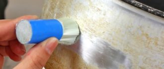
Before starting work, remove slag, scale and other contaminants from welded joints. To better see the defects, the seams are treated with nitric acid (10%). This gives the seam a matte finish, making it easier to find flaws.
After acid treatment, it is necessary to thoroughly wipe with alcohol to prevent its harmful effect on the alloy.
To improve the quality of the inspection, you can use a flashlight and an optical magnifier. To control geometric dimensions, calipers and templates are used.
Capillary method
This control method uses the property of liquid to be drawn into very small capillaries. The speed and degree of penetration into the material is related to its wettability and the diameter of the capillaries. The alloy is more wetted and the capillaries are thinner - the liquid penetrates deeper.
The capillary method of weld quality control allows you to deal not only with any metals, but also with ceramics, plastic, and glass. Its main use is associated with the manifestation of external flaws that are impossible or difficult to detect with the naked eye. Sometimes, using, for example, kerosene, you can detect through defects.
The method is very simple, it has been working since the need to check welding seams arose. A special GOST 18442-80 has even been developed for it.
In the capillary welding quality control method, penetrants are used - substances that have low surface tension and strong color contrast.
By penetrating into defective areas and highlighting them, penetrants visualize welding flaws. They are made from water, kerosene, transformer oil and other liquids.
The most sensitive penetrants can show defects as small as 0.1 microns in diameter. The capillary welding quality control method is effective for defects up to 0.5 mm wide. It does not work for large pore diameters or cracks.
The method using penetrants involves cleaning the surface, applying a control liquid and revealing flaws. A very effective way to control welded joints is using kerosene.
Despite the variety of welding quality control devices, testing by this method is still used. A chalk solution is applied on one side, time is allowed to dry, then the seam on the other side is lubricated with kerosene. Defective areas appear after a few hours in the form of dark spots.
Checking welded joints for permeability
If welding is used in the manufacture of tanks, tightness control is required. To do this, tests for tightness of connections are carried out. Quality control is carried out using gases or liquids.
The essence of the method is based on creating a large pressure difference between the outer and inner areas of the container. With through-hole flaws in the weld, liquid or gas will flow from an area of high pressure to an area of low pressure.
Depending on the substance used and the method of obtaining excess pressure, permeability control is carried out by pneumatics, hydraulics or vacuum.
Pneumatic method
The use of a pneumatic welding quality control method requires pumping the tank with some gas to a pressure of 150% of the nominal pressure.
Then all welds are moistened with soapy water. Bubbles form in places of leakage, which is very easy to fix. For better visualization, an ammonia additive is used, and the seam is covered with a bandage soaked in phenolphthalein. Red spots appear in areas of leakage.
If it is not possible to pump up the container, then use the blowing method. On one side the seam is blown under a pressure of at least 2.5 atmospheres, and on the other it is coated with a soap solution. If there is a defect, it will appear in the form of bubbles.
Hydraulic method
With the hydraulic method of welding quality control, the container being tested is filled with water or oil. An excess pressure is created in the vessel, which is one and a half times more than the nominal pressure.
Then, for a certain time, usually 10 minutes, the area around the seam is tapped with a hammer with a rounded head. If there is a through welding defect, a leak will appear. If the excess pressure is small, then the holding time of the tank is increased to several hours.
Magnetic flaw detection
The phenomenon of electromagnetism is used in magnetic flaw detectors. Each metal has its own degree of magnetic permeability. When passing through inhomogeneous materials, the magnetic field is distorted, which indicates the presence of foreign elements inside the structure.
This is used in the welding quality control instrument. It produces a magnetic field that penetrates the metal being tested. Inhomogeneities are recorded using magnetic particle or magnetographic methods.
In the first case, ferromagnetic powder is applied to the weld. Where the accumulation of powder occurs, there is most likely a lack of penetration, there is no continuous connection. The powder can be dry or wet, mixed with oil or kerosene.
In the second case, ferromagnetic tape is applied to the seam. It is then passed through a device where all anomalies recorded on the tape are analyzed and welding defects are determined.
The magnetic method of quality control has limitations associated with the very principle of operation of the device. It can only check the quality of welded joints of ferromagnetic materials, which do not include some steels and non-ferrous metals. Accordingly, this control method has limited application.
Ultrasonic flaw detection
Ultrasound is used to control welding quality. The operating principle of the device is based on the reflection of ultrasonic waves from the boundary between two media with different acoustic properties.
The sensor and emitter are tightly applied to the material being tested, after which the device produces ultrasound. It passes through the entire metal and is reflected from the back wall, returning to the receiving sensor, which in turn converts ultrasound into electrical vibrations. The device presents the received signal in the form of an image of reflected waves.
If there are any flaws inside the metal, the sensor will record a distortion of the reflected wave. It has been experimentally established that various welding defects manifest themselves differently on an ultrasonic flaw detector. This made it possible to classify them. With appropriate training, a specialist can accurately determine the type of defect in a seam.
The method of ultrasonic quality control of welded joints has become widespread due to its simplicity and ease of use, relatively inexpensive equipment, and safety of use compared to the radiation method.
The disadvantage of this method is the difficulty of deciphering the graphic image. Connection quality control can only be done by a certified specialist. It is problematic to use it for testing coarse-grained metals such as cast iron.
Radiation method
To control the quality of welding, radiation methods and devices are used. In essence, this is the same X-ray machine used in hospitals, or a device with a gamma radiation source, adapted for irradiating welded joints.
It is based on the ability of these rays to penetrate any materials. The intensity of penetration depends on the type of substances being tested. Thanks to this, an image characterizing the condition of this material remains on the photographic film behind the product under study.
All welding defects in the form of inhomogeneities are revealed on the film. The control method is very accurate, but expensive and harmful to people; it requires preparatory work to install protective screens and carry out organizational measures.
Paperwork
A special magazine is provided for welding. It is the primary document drawn up in accordance with the requirements of SNiP. The design organization draws up a list of components in the metal structure that must be handed over to the customer with the preparation of welding documents.
In addition to the magazine, welding work is accompanied by a diagram of the joints, certificates for consumables (electrodes, flux or filler wire) and quality control reports on the outside of the product are attached.
If ultrasound or other specific studies were carried out, the results and conclusions on them are also attached.
All this allows us to talk about the quality of welding and reliability of the design. Only after the welding documentation has been submitted in full are further procedures for accepting the metal structures of the facility carried out.
Source: https://svaring.com/welding/teorija/kontrol-kachestva-svarki
Steelscoping of welds
During welding of metal products, various defects can form on the surface of the seam, as well as inside it. Any of them reduces the quality of the connection, so that when exposed to loads, this place may break. Some of them lead to depressurization of the cavity, since they contain microcracks, which is unacceptable for the operation of such products.
But under the temperature effect that occurs from the welding arc or gas, some alloying elements may evaporate. To identify the presence of defects even before using the parts directly, there are various methods. One of these is steeloscopy of welds. This method is set up to determine the amount of alloying elements in the weld.
Spectral analysis is used here.
Steelscoping of welds
Steelscoping of welds and base metal is used for pipelines, boilers and other products made from alloy steel. When a metal is heated to a high temperature, steam emits from it. Each metal has its own unique spectrum, from which it is possible to determine what exactly is included in the composition.
When welding alloyed metals, additional materials are often used, which are designed to compensate for the disadvantage that occurs due to burnout. Steelscoping of welds for stainless steel and other metals can be carried out twice.
If satisfactory results are obtained the first time, then there is no need for repeated analysis, but otherwise the procedure is carried out a second time, only this time the number of points is increased. If this time the results are unsatisfactory, then a chemical analysis of the parts is carried out. This analysis is already final.
If during it it was possible to find a non-compliance with the requirements, then all welds of the same type that were performed by the same welder undergo steeloscopy.
Steelscoping of metal welds
To carry out the procedure, a special device is used, which is a steeloscope. It can be used both in the laboratory and in the workshop. The determination of which specific grade of metal a particular fragment belongs to is determined by the operator of the device.
This method is practically not used in the private sphere or when working with metal structures, which have relatively little responsibility. It is relevant in places where precise adherence to the composition is required.
This can be welding stainless steel and other high-alloy alloys.
Advantages
- Thanks to this method, you can find out its composition without destroying the product;
- The devices are safe for human health;
- The equipment can be located directly in the work shop;
- Works in a narrowly focused area.
Flaws
- This method is quite complicated to implement and requires special training of operators;
- Operator training for entry-level work requires about two months, and for normal analysis a person must work for about six months to understand all the nuances of the data received;
- It is difficult to determine the presence of impurities;
- The results very much depend on the subjective human factor and operator experience;
- Here it is impossible to know the content of sulfur, carbon and phosphorus in steels, although these elements can be very harmful to the metal;
- Long-term work here, although it does not have radiation effects, as happens with radiographic inspection of welded joints, does damage vision over time.
Design and principle of operation of the installation
Having understood what steeloscopy of welds is, it is worthwhile to dwell in more detail on what a steeloscope is and how it works. This is a device that has an autocollimation optical system. This system has a photometric wedge. The device is protected by a housing casing. The steeloscope itself has a built-in arc generator.
One of the features of the device is that its optical design is elongated in the horizontal direction. From the light source, radiation passes into a slit, which is located in a three-lens lighting system.
Each lens has its own focal length, which is 50, 60 and 70 mm. Thanks to this, the gap receives uniform illumination. Its size is only 0.02 mm.
A slit is cut in a metal plate placed on a glass piece that is glued to the lighting lens.
Steeloscope
The light beam is directed onto the lens using a trapezoidal prism. The focal length of this prism is 275 mm. One dispersing prism is fixed motionless. Another prism has a mirror coating that can be rotated.
This is necessary so that the spectrum can move exactly into the field of view of the eyepiece. When the rays hit the silvered side of the movable prism, they pass through two more previous ones and hit the mirror.
And only by being reflected from it do they enter the eyepiece, where the operator can see them.
The principle of operation of the steeloscope
The device may have several interchangeable eyepieces. Accessories with 13x or 20x magnification are often used. The lower the magnification, the higher the field of view. This is especially useful when analyzing spectra that have a relatively small number of lines. The photometric wedge is located in the focal plane of the eyepiece.
This is a narrow strip of platinum layer fixed between two glass plates. Thanks to it, the capabilities of the device become significantly wider. It provides uniform illumination of the slit, but the intensity of the spectrum becomes relatively small.
The arc generator that comes with the device is placed directly under the spectral apparatus
Analysis methodology
Styling welds is carried out in accordance with GOST 7122-81. To begin with, the product is prepared before analysis. All unnecessary parts, such as slag, metal particles are removed from it and the surface is cleaned. The sample is then placed near the copper electrode of the steeloscope and the discharge is ignited.
It can be arc, spark or a combination. At this time, the operator observes what color spectrum this discharge had. By rotating the handle of the device, you can view the entire spectrum from the red to violet region.
Particularly visible are those areas that correspond to the color of impurities.
The search for such an area is carried out using the atlas for the steeloscope. When the operator has managed to identify such a line, he compares the brightness of its glow with those lines that border the base. Next, using the corresponding tables from the same atlas, he determines the concentration of the impurity relative to the brightness of its glow. To accurately determine the results, experiments are carried out several times.
Security measures
This method is completely safe for humans, so it is enough to apply basic electrical safety measures. The device should not be allowed to overheat, and if this has already happened, then it should be allowed to cool.
Source: https://svarkaipayka.ru/tehnologia/drugoe/stiloskopirovanie-svarnyih-shvov.html