How to connect welding cables to each other - 3 simple ways
14.01.2019 1194
The length of the wire that comes with the welding machine is insufficient, the cord breaks or is damaged during operation - reasons why it may be necessary to connect the welding cables to each other. The quality of the work performed and human safety will depend on the reliability of the contact connections of the conductors.
The length of the wire that comes with the welding machine is insufficient, the cord breaks or is damaged during operation - reasons why it may be necessary to connect the welding cables to each other. The quality of the work performed and human safety will depend on the reliability of the contact connections of the conductors.
Features of welding cables and their connections
The welding cable is used as a connecting link between special electrical holders and the current source. It is made of copper or aluminum wire, has a large cross-section and insulation, providing protection from moisture and mechanical damage. Products of this type are characterized by:
- high flexibility,
- minimal resistance.
Before connecting the welding cables to each other, it is necessary to clean them from the oxide film.
Important! Only wires made of homogeneous metals can be connected to each other - copper to copper, aluminum to aluminum.
In what cases is a connection needed?
Inverters for welding are equipped with short wires, which creates difficulties when performing work at heights and in hard-to-reach places. Connecting welding cables using soldering, welding or installing special connectors expands the capabilities of the equipment and eliminates the need to hold it on the shoulder. When carrying out this task, it must be taken into account that the maximum length should not exceed 30-40 m.
Common connection methods
Before connecting the welding cable using the crimping method, you must purchase aluminum or copper sleeves. You can select products in the catalog. There is a wide range of connectors, components and other electronic components - cables, assemblies, printed circuit boards - of high quality and affordable cost.
Soldering is the second popular method of connecting copper cables. It involves coating the preheated ends of the cores with molten solder. After hardening of the latter, high strength and good electrical conductivity of the product are achieved. This technology is suitable for conductors of small cross-section.
The main advantages of soldering are simplicity and cost-effectiveness. Preparatory activities include:
- getting rid of isolation
- twist,
- cleaning,
- flux treatment.
After soldering, it is necessary to wash off the residues, apply varnish, insulation in the form of tape or shrink film.
Important! The intermediate stage of soldering is twisting the wires. As an independent method, it is prohibited by the regulatory documents of the PUE.
Since welding allows you to connect 2 large-diameter welding cables into a monolithic structure, this method is often used. To connect the wires, a special device VKZ-1, similar to a pistol, is used. The advantages of the method are high contact strength, resistance to mechanical stress, the disadvantages are the need to strip the wire by 10 cm, the difficulty of choosing the current strength, the impossibility of separating the elements.
Connecting the welding cable with connectors
The simplest and most effective method of connecting welding conductors is the method using connectors. To do it correctly, you need to choose wisely:
- welding cable brands,
- connectors,
- tips,
- plugs and terminals.
The choice of cable connector depends on the conductor cross-section. The latter can be determined using a micrometer or caliper. The connector can have an area of 10, 25, 35120 mm2. There are two designs of devices - pin (“male”) and female (“female”).
To connect them to the equipment, you need special sockets that act as a response component of the plug.
When purchasing lugs, you need to pay attention to the standard size (must correspond to the cross-sectional area of the wire) and materials of manufacture. Preference should be given to products with chrome plating, which prevents oxidation.
The crimp connection is extremely simple. It consists of stripping products of insulation, combining cores into bundles, putting on connectors and clamping them.
Tip Installation: Process Principles
Since it is correct to connect a welding cable using lugs, this procedure is most often performed to lengthen and create a convenient shape for the end of the conductive core necessary for connection to the clamp of the device. To do this, you need to strip and treat the wire with paste, place the tip on the end of the cable and press it until it stops. After this, the product should be crimped using tongs or a matrix press.
To increase the mobility of the welding machine, you can extend the wire using different connection technologies. Specialists from our company “VKS” recommend using connectors selected according to the cross-section and composition of the core bundle, observing the sequence and rules of the method used. To purchase electrical components, you need to go to the catalog.
If difficulties arise with the choice, our manager will provide professional advice.
Source: https://cabsystems.ru/news/kak_soedinit_svarochnye_kabeli_mezhdu_soboy_3_prostykh_sposoba/
How to connect a welding machine
Before welding, at a minimum, you need to understand how the welding machine is connected to the existing network, as well as what conditions must be observed.
To quickly and efficiently connect the welding machine, you should follow the current operating instructions for devices of this class.
Of greatest interest from the point of view of the features of this process is the connection of a welding inverter, most often used at home.
Safety regulations
The connection diagram for an inverter welding machine is quite simple and allows the device to operate in a cyclic (intermittent) mode, which allows for maximum welding efficiency. Before plugging into a socket, you still need to read the connection instructions, check the network parameters, completeness of the equipment and the external integrity of all its parts .
Options for connecting the inverter to the network
The instructions should clearly describe how to properly connect the welding machine, and also stipulate the procedure for its safe connection to the current electrical network. The need to check plugs and circuit breakers installed in the power supply circuit is specifically stated.
The fact that in old houses aluminum wiring does not allow working with currents above 10 Amperes should also be taken into account. Therefore, before connecting converters to the network, it is necessary to find out their rated power and current consumption.
When assessing the power taken from the network, one should not forget that when the device is turned on, there is a sharp surge in the starting current, the value of which can exceed the rated value several times.
Before connecting the device and welding work, the operator must fulfill the following requirements of the operating instructions:
- remove foreign electrical devices (computers, transmitters, measuring instruments) from the device body;
- when working with inverter equipment, the workplace must be cleared of all other interfering objects;
- The rooms in which the welding unit is located must be equipped with a forced ventilation system.
To avoid emergency situations, before connecting the welding machine for the first time, it is recommended to test it in various welding modes.
Turning on the device (operating instructions)
When considering the operating conditions of a welding inverter, first of all, you need to pay attention to the following points:
- the normal duration of the current load should not exceed 5 minutes;
- in practice, the so-called “three-minute cycle” is usually used, which is two-thirds of the full load;
- If strong heating of the case is detected, the device must be turned off until the causes of the overload are determined.
Welding using an inverter machine requires careful preparation, since dangerous situations are possible when working with equipment of this class. Before starting welding work, the operator must fulfill all the requirements of the operating instructions, including choosing the appropriate current mode and electrode type .
Connecting the inverter to the network and putting it into operation is allowed only after meeting safety conditions, including the use of sockets and plugs of the appropriate standard.
When operating a welding machine, you should use special coated electrodes (MMA type).
The thickness of MMA electrodes is selected based on the mode and type of metal to be worked with. Typically, the thicker the metal, the greater the current required and, accordingly, the diameter. The most common ones used at home are 2 and 3 mm electrodes.
Before starting welding, make sure that the electrodes are dry. The wire going to the torch is connected to the minus terminal, after which the gas hose is connected to the reducer located on the cylinder if welding is performed in a protective environment.
When connecting via an extension cord, you need to pay attention to the cross-sectional diameter of its cable. The cross-section must be at least 1.5 square meters. mm for working with current up to 16 A. The wire must be completely untwisted so that there is no inductance, which, after connecting the welding machine, will create additional resistance.
Launch Mode Features
The inverter is put into operation by pressing the “Start” button, which leads to a state of complete readiness for welding procedures. To start welding in a protective gas environment after connection, just slightly unscrew the torch valve, install the desired electrode and “strike” it on the workpiece to be welded.
When considering starting an inverter, the following must also be considered. The fact is that any inverter device is equipped with a soft start device that prevents the failure of the electronic elements of the circuit from a surge of current.
Despite such protection, current surges when turned on can reach values of the order of 40 Amperes, which are dangerous not only for the outlet, but also for the existing electrical network due to the strong “sag” of voltage.
During current surges within the above limits, the mains voltage may decrease (“sag”) from 220 to 130-140 Volts.
It is recommended to connect the power supply circuit of the device to the terminal contacts located directly on the distribution panel, where the grounding bus is also supplied separately. For a machine installed in an input device, such voltage drops are less dangerous.
The situation with inrush currents is significantly simplified when linear rather than phase voltages are used to power the inverter. However, this option can be implemented only for devices designed for 380 Volts and provided that the house is connected to a three-phase network (generator).
When considering the features of putting an inverter device into operation, one should not forget the features of adjusting its load current, which is carried out automatically (using a special control unit). Setting elements that set the control limits are located on the front panel of the device.
Compliance with the instructions for connecting pulse converters is mandatory for all models of welding devices without exception. Only if the starting conditions for inverters are met is it possible to maintain their functionality and guarantee high efficiency of the welding process.
Source: https://svaring.com/welding/apparaty/podkljuchenie-svarochnogo-apparata
How to connect cables to a welding inverter
A welding inverter is a device that can greatly facilitate the arc welding process. Every year its use becomes more and more popular, because it allows welding of any structures quickly and efficiently. In order for welding work to take place in the required modes, and for the device to have a long service life, you need to correctly connect the inverter to the power source. Therefore, further we will consider how to properly connect a welding inverter.
Diagram of the device of an inverter welding machine.
Connecting a welding inverter
The welding machine can be connected to an external network with a voltage of 220 V or 380 V, or to a generator set of a certain power. The connecting cable with plug corresponds to the maximum power of the unit, so there should be no questions here. The main difficulties may arise from an external power source, especially if the electrical wiring in the summer cottage is old and has an unknown cross-section.
Modern wiring, plugs and sockets are designed for a current of no more than 16 A. The total power consumed by all devices in the house can be more than this value, so it is limited by an automatic safety device or a regular plug. To connect a welding inverter, you first need to make sure that its input power will not disable the home network protective device.
Welding inverter device.
One of the advantages of this type of welding devices is that their electrical circuit has several types of protection. In case of network overload, the protection automatically turns off the device due to low voltage. This situation can occur when the input voltage is low, or in the case of insufficient electrical wiring, the resistance of which will reduce the voltage when a load in the form of welding current occurs.
If the electrical wiring of a fixed network does not allow connecting an inverter, you need to use other power sources, which will be discussed below. If the maximum power of the device fully matches the external wiring, you can connect the inverter to the mains and carry out test welding.
It is not recommended to connect to the network if a fuse of unknown rating is installed as a protective device.
If possible, you need to control the voltage drop when igniting the arc. Severe subsidence may be the result of a small cross-section of wires.
Connecting a welding inverter to an electric generator
Due to poor parameters of the external electrical network, in some situations it is simply impossible to carry out welding. Then you can use the power plant. At the same time, it is very important that the power of the power plant allows for full-scale welding work.
When choosing a generator, you should first familiarize yourself with the basic technical characteristics of the welding machine. As an example, we will take a conventional inverter with an operating current of 160 A. Modern inverters have smooth adjustment of the welding current from minimum to maximum value. This allows welding to be carried out at both medium and maximum power of the equipment. But manufacturers often write only power consumption, without saying anything about its maximum value.
Figure 1. KG brand wires are different and differ in maximum load, depending on the cross-section.
To independently calculate the maximum power, you need to multiply the maximum operating current of the device by the arc voltage (usually it is 25 V), and then divide the resulting figure by the efficiency of the inverter (approximately 90%). As a result, the maximum power will be equal to: 160x25/0.9=4444 W.
After making the calculations, you can begin to select an electric generator. In this case, you should focus on the maximum power consumption, adding a reserve of 25% to it, so as not to use the power plant to its maximum capacity. Therefore, for a welding inverter with an operating current of 160 A, you need to buy a generator with an output power of at least: 4444+4444x0.25=5555 W, or 5.5 kW.
Gasoline generator or electric generator?
Connection diagram of the inverter to the battery.
In some cases, if it is impossible to use an external power supply, welders try to connect inverter welding through a low-power gas generator. This approach is incorrect if its power is less than 5 kW. The operating voltage in such generators strongly depends on the load size. Inverter devices are sensitive to voltage changes, so if the output voltage of the gas generator changes frequently, the welding machine may fail.
When welding with a 3 mm electrode, the operating current reaches 120 A at a voltage of 40 V. In this case, the output power will be: 120x40 = 4800 W, or 4.8 kW, that is, the gas generator will operate at maximum power, which will also lead to its premature exit building. Therefore, if the network is poor, it is better to connect the welding machine to an electric generator.
Selecting a cable to connect the inverter
To carry out high-quality welding, it is very important to choose the right connecting wires. Welding wires are selected according to the following indicators:
Functionality of the welding inverter.
- length;
- cross-sectional area;
- the value of the voltage drop in the welding circuit.
The inverter cable is a flexible current conductor with good insulation. In most cases, such a wire is made of copper wires 0.18-0.2 mm thick, woven together. Such cables are used to connect the inverter to the electrical holder, as well as to ground the device. The choice of wires depends on their technical characteristics and the characteristics of the welding unit itself.
Among welders, the most popular is the KG brand wire (Fig. 1). Manufacturers of this type of cable recommend its use in alternating current circuits with a voltage of no more than 600 V or in direct current circuits with a voltage of no more than 1000 V.
KG brand wires vary in maximum load, depending on the cross-section. The ratio of the maximum load on the cable and its brand is presented in the table:
| Cable brand | Permissible load, A |
| KG 1x16 | 189 |
| KG 1x25 | 240 |
| KG 1x35 | 289 |
| KG 1x50 | 362 |
| KG 1x70 | 437 |
| KG 1x95 | 522 |
In addition to the KG brand, KOG1 brand wire is also used, which is more flexible than the first option. It is used in cases where the welder needs to constantly move to perform work.
https://www.youtube.com/watch?v=SmWukRgOebY
Connecting the welding cable is carried out taking into account certain rules:
- Connections should be made using pressed or soldered lugs.
- The cable is connected to the power connectors of the unit (+) and to the electrode holder in reverse polarity (-). The polarity can only be changed when the current parameters are changed.
- When carrying out welding work, the welder is prohibited from pulling the inverter towards himself with wires.
- Under no circumstances should the rated power of the cable be exceeded.
Connecting welding inverters using extension cords
Carrying out welding work is often associated with the remote location of the welded structure from the power source. Sometimes in such cases it is necessary to use an extension cord. An extension cord for an inverter is a conductor that has some resistance, which causes a voltage drop in the electrical circuit, that is, the longer the extension cord, the greater the operating voltage drop across it.
Source: https://MyTooling.ru/instrumenty/kak-podkljuchit-kabelja-k-svarochnomu-invertoru
How to connect welding leads to a welding inverter
The inverter welding machine has gained wide popularity among home craftsmen and small repair shops. To obtain a strong and durable seam, a powerful and serviceable machine is not enough. High-quality wires for the welding inverter of suitable cross-section, type and length are also required.
Device
Of the available metals, copper serves as the best conductor . Combined with its flexibility, this makes it an ideal material for making the base of welding wire - conductors.
The structure consists of the following main parts:
- copper core, twisted from a large number of copper wires with a diameter of up to 0.5 mm;
- separating layer - a thin shell that prevents the core and the insulation layer from sticking together, can be supplemented with talc or other powder;
- an insulating coating consisting of rubber, rubber or other polymer.
The ends are provided with contacts to connect to the inverter and holder. They are crimped and soldered to ensure the best contact.
Characteristics
The most important characteristic required for a wire is its cross-section . It determines the maximum current passing through the cable. No less important is the resistance, which causes electricity losses on the way from the device to the electrode. Mechanical parameters are of great importance:
- strength: ability to withstand loads;
- elasticity: the ability to return to its original shape after deformation
- temperature resistance: the ability to maintain working properties when temperature changes;
- ability to withstand sunlight and humidity;
- resistance to fungus and mold;
Kinds
With household and semi-professional class inverters, the most common in home workshops, single-core wires of the KG brand are mainly used.
Depending on their purpose and characteristics, they are:
- KG-HL , insulation is made of frost-resistant rubber, they work in the cold;
- KG-T , insulation impregnated with substances that prevent the growth of fungus and mold, used in humid climates
- KOG , highly flexible wires, for welding in hard-to-reach places, for example, in shipbuilding.
According to the number of cores they are divided into:
Single-core
Most of the inverter wires are single-core.
One wire connects the device terminals to the electrode holder, the other to the ground clamp on the workpiece.
Twin-core
Used for high frequency welding and alternating current operation . Two cores have their own insulation; the outside is covered with another insulating layer. Alloys of copper and other non-ferrous metals are used as materials.
Three-core
Such wires are used to connect automatic welding systems connecting pipelines and large containers.
Each core also has its own insulation.
Section selection
The correctly selected welding cable cross-section for the inverter will allow you to work safely and with the expected performance. If the wire cross-section is insufficient, the resistance of the wire will cause loss of current due to its heating; as a result, the machine will not be able to develop the required welding current and the quality of the seam will deteriorate sharply. In this case, the indicator on the inverter will blink , indicating an overload.
In order to connect low-power portable inverters operating from a 220V network, light and flexible wires with a cross-section of up to 16 mm2 are used.
For more productive devices, a cross-section of up to 50 mm2 will be required.
Correct connection
Proper connection ensures the welder productive and safe work.
Connecting wires to a welding machine requires compliance with a number of rules:
- there must be a terminal at the end, crimped or soldered;
- The wire cross-section must correspond to the maximum operating current of the device plus a margin of 20%
- You should carefully monitor the polarity of the connection and observe it;
- The cable must lie freely in the work area, without tension or loops.
How to connect a welding machine if there is not enough wire to the welding zone? You can increase its length.
Is it possible to extend the welding cable on the inverter?
When increasing the length, you need to understand that the longer the cable for connecting the welding inverter, the greater the losses and the lower the resulting current strength.
If it is necessary to weld at a great distance from the machine, wires of a larger cross-section should be connected to compensate for losses.
When splicing 380V cables equipped with terminals with a hole into a single circuit, they should be cleaned and securely connected with a bolt and nut, not forgetting to install large diameter washers. The connection point must be carefully insulated, taking into account the fact that the wire will be repeatedly pulled through metal and concrete.
How to connect an inverter if there is no crimped terminal on the cable? Wires are spliced by repeatedly interweaving the wires that make up the core . Then the connection point should be soldered and crimped.
There are also special extension cables that have crimped and insulated connectors. Their type must match the connector of your device.
Manufacturers do not specify any restrictions on cable length. In each case, the welder himself decides what is better - to lengthen or drag the inverter and gas generator more often .
Marking of welding cables
The welding wire marking consists of several groups of letters and numbers. From it you can understand which model is in front of us.
First there are several letters indicating the type of cable.
After the type, a dash may indicate the climate class of the wire:
Next comes a number indicating the number of cores - 1, 2 or more. The designation is completed by the cable cross-section in mm2.
Safety requirements
When welding work, the following requirements must be observed:
- Do not work with wires with damaged insulation or insufficient cross-section;
- the wire in the working area should be placed freely, without clinging to the welder’s hands or feet;
- there must be enough light in the working area for the welder to move confidently;
- When connecting to the device, polarity must be observed.
Correctly selected wires for a welding inverter are the key to safe and productive work . You need to pay attention to the cross-section, length and climate class of the cable. Cable extension can be carried out in strict accordance with the requirements of the regulations.
Source: https://svarka.guru/oborudovanie/rashodniki-i-kompletuyushie/provoda-k-invertoru.html
Connecting the welding machine to the electrical network: rules and algorithm, safety precautions
Surely, after purchasing an inverter welding machine, in the box you will find instructions for operating the device. After reading it, you will most likely notice that proper connection to the network will be mentioned in passing.
And in vain, because the matter is not limited to simply inserting a plug into a socket.
It is dangerous to carelessly connect such complex equipment to your home network without taking into account its properties and nuances. As a result, you can easily destroy the welding inverter itself or the wiring in the building. What do you need to know about properly connecting a welding machine?
Below we briefly summarize the main points that you should pay attention to when connecting a welding inverter to a 220V household outlet.
Preparing to connect
Before connecting the welding inverter, you should make sure that the wiring in the building is suitable for welding work. First of all, inspect the outlets.
If they were installed more than a quarter of a century ago, then there is a good chance that the wiring has not changed since then. It’s good if it can withstand high voltage, but this is rather an exception to the rule.
Usually such wiring only adds difficulties to the work. In this case, you will not be able to work with a modern inverter machine, even using the latest welding cables.
You don't have to have an engineering degree to imagine the consequences of connecting a powerful inverter to an old outlet.
You risk cutting off power not only to your workspace, but also to neighboring buildings, and electrical appliances may become unusable.
Before starting work and connecting the inverter, it is necessary to check the condition of the wiring. Don't give up if you find out that your wiring may not be able to handle the load.
You can get out of this situation by using a current generator. How to do this is described below. Now we suggest considering options for connecting an inverter welding machine to the network.
Using Generators
If the wiring test result is unsatisfactory, connecting the inverter is unacceptable. But there is always a way out. Electric generators can be used.
Many people have gas generators that can help out in the absence of electricity. In theory, their use may seem like a great idea.
In fact, it turns out that such generators have low power, and supplying a voltage of more than 5KW is an impossible task for them.
Obviously, there is no point in connecting an inverter device to a generator with low power. The minimum required power value can be found by multiplying the cooking current by the voltage value.
Let's consider a standard connection diagram. When welding with a 3 mm electrode and a current of 120A and a voltage of 40V, you need to multiply 120 by 40. This means the required power value is at least 4.8 kW.
Considering that the efficiency of the inverter is less than 100%, for stable operation of the welding machine you will need at least 6 kW.
So, a gasoline generator can be used when no other power source is available. It is more logical to check the wiring at the planning stage of purchasing an inverter device.
If it does not meet the requirements, there is a solution to purchase a device with an already built-in generator. The only disadvantages of these models are the price and large dimensions. But sometimes there is no other way to solve the problem.
If this option is not relevant for you, pay attention to the current stabilizer for the welding inverter. You can connect the device to it in a relatively stable network.
Selecting extension cords
Particular attention should be paid to the use of extension cords when connecting inverters to the network. If the extension cord is incorrectly selected, the efficiency of the welding inverter decreases and the voltage drops.
The configuration of welding machines usually includes a cable about 2.5 m long. For simple work, this length is enough, but in case of frequent movement or welding at height, it will not be enough.
Therefore, it will not be superfluous to learn about connecting extension cables. Under no circumstances connect them at random! You will need to calculate the exact cross-sectional size of the extension cable.
This value is directly related to the maximum power that the wire can withstand.
Using the above diagram, let's give an example. The current we need when welding is 120A. We get 16A when using a cable with a cross section of 2.5 sq. mm.
Proportionally, for a welding current of 120A, the cross-section of the extension cable must exceed 12 sq. mm. Do not forget about safety precautions, remember about grounding and untangle the cables before starting welding, for faster cooling.
It is much more efficient to buy one cable of the required length than to connect several short ones to each other. This way, the contact connections of the extension cord will be more durable, and the possibility of losing the efficiency of the welding inverter will be reduced.
CONCLUSION
The described technology for connecting an inverter welding machine to the network is simple.
It is worth understanding the importance of these rules, remembering them and successfully applying them in practice in the future.
When connecting a transformer, semi-automatic device or 380V device, the sequence of actions is the same. Successful work!
Source: https://prosvarku.info/tehnika-svarki/kak-pravilno-vypolnit-podsoedinenie-svarochnogo-apparata-k-elektroseti
How to properly connect a welding inverter plus minus
- No welding machine can operate without the proper electrical cables. In this article we will briefly talk about how to connect welding cables directly to the inverter and what you need to know before starting work. In fact, the welding machine has not two cables, as is usually believed, but three. Why is that? – It’s very simple, because many people simply forget about the most important cable – the power cable. Without it, the welding machine simply will not turn on. And with it, things are simplest - just connect it to the inverter, to the corresponding and only connector on the back of the welding machine body. Things are somewhat more complicated with welding cables for connecting electrodes and the ground clamp. In order to connect them, in front of the housing of the welding inverter there are two connectors marked plus “+” and minus “-”. Be careful, since in this case the cables must be connected correctly. Thus, the cable for power supply to ground must be connected to the minus “-” connector, and the cable with the electrode holder must be connected to the plus “+” connector accordingly. Before connecting the cables, they must be visually checked for integrity, and there is no short circuit between the electrode holder cable and the ground cable. After the cables are connected, make sure that the device and wires are on a clean and dry surface. Connect the power cable to ground to the welding table or workpiece. Connect the electrode to the electrode holder, turn on the welding machine, set the required welding current value and get to work. That's all you need to know about connecting welding wires to the welding machine. Once again, carefully connect the cables to the appropriate connectors, without confusing the plus “+” and minus “-”. In the case of a reverse connection, when the ground is connected to the plus and the electrode holder to the minus, this method is called a connection with reverse polarity.www.vse-o-svarke.org
- The inverter is connected to the battery.
- Other necessary devices are connected.
- If necessary, use an extension cord.
- A test run of the machine and welding is carried out.
- KG 1x16 189 A;
- KG 1x25 240 A;
- KG 1x35 289 A;
- KG 1x50 362 A;
- KG 1x70 437 A;
- KG 1x95 522 A.
- For connections you need to use soldered or pressed lugs.
- You cannot pull the inverter towards you using wires for this.
- The wire must be selected in accordance with the rated power.
- At home, it is recommended to use an extension cord up to 20 m long.
- The extension cord must not be wound onto a reel to prevent overheating and failure due to inductance. Heating of the wire should not exceed 70° C.
- The place for welding work should not be cluttered.
- It is not recommended to use the inverter in cold weather, in very dusty conditions, or near piles of metal shavings.
- In conditions of high humidity, a canopy is required.
- It is recommended to take regular breaks from use to allow the machine to cool down.
The duration of welding and rest are indicated in the instructions.
- When working, you should use personal protective equipment. Be sure to use a jacket, gloves and a protective mask with a properly selected light filter.
- Position 1 is a welding station;
- number 2 indicates a three-core hose cable;
- 3 - transformer;
- 4th position - regulator;
- number 5 - grounding clamps of the unit body;
- 6 - single-core hose cable;
- 7th position - electric holder;
- number 8 - ground wires.
- the unit itself;
- extension;
- adapter for extension cord.
- First, a plug is prepared with the appropriate thermal throughput parameters.
- Select a socket with a circuit breaker or fuse.
- The return cable is connected to the terminal.
- The holder cable is connected to the electrode fragment using a clamp.
- The minimum distance from walls and large objects is 2 meters.
- Protective grounding is mandatory.
- There should be no flammable or explosive objects or substances nearby.
- For welding work, you should use a metal table or just a free platform.
- With a welding current of 160 A, you can only work with electrodes with a largest diameter of 4 mm. The active power of such an inverter is 3.8 kW, and the total, taking into account the coefficient of 0.7, will be approximately 5-5.5 kW. Taking into account the 20% power reserve, a generator of at least 6 kW will be required.
- Welding current of 180 A allows work with 5 mm electrodes. Active and apparent power will be 4.8 and 7.5 kW, respectively. Therefore, the generator power should be no lower than 8-8.5 kW.
- If the welding current reaches 200 A, then such equipment needs a three-phase network. The diameter of the electrode increases to 6 mm. The total power of the inverter will be 11.5 kW, and the power of the three-phase generator will be no less than 15 kW.
- the cable must meet the technical requirements for it: resistance to impacts, breaks, bends, aggressive chemical environments, temperature changes, ultraviolet radiation, mold formations;
- The cord must withstand the maximum current that the welder’s unit produces.
- “Welding cable KG”;
- “Welding cable KOG.”
connection to the mains and battery
Many home craftsmen have a welding unit in their workshop. It can be of different types. Today, specialized stores have quite a large selection of this equipment, including a welding inverter (image No. 1). This is a unit that has certain advantages over other welding units. It has an attractive appearance, light weight, and great mobility. It can be powered from a household and industrial network with a voltage of 220 V and 380 V, from batteries and generators producing a voltage of 12 V and higher. Image 1. Diagram of a welding inverter.
Connecting the inverter to the power grid
The connecting cable supplied with the unit corresponds to the power of the device. You just need to check the technical data of the wiring in the house. It may turn out to be old and does not meet modern standards. Nowadays, all wiring, switches and sockets, and safety devices are designed for an operating current of 16 A. Before connecting the welding inverter, you need to make sure of this. Although the installation should turn off itself if the diameter of the wires is small. If everything is fine with the network, you can connect the inverter and do test welding. If instead of a standard fuse, a “bug” is installed in the electrical network, the parameters of which are unknown, it is not advisable to connect the welding inverter to such a network.
Connecting the inverter to the vehicle's on-board network and to the generator
Functional diagram of the power source of an inverter welding machine. Connecting a welding machine to a car battery is usually not difficult. Light weight of 2.5-3 kg makes it easy to transport the device to the car. Small dimensions of about 300 x 190 x 130 mm allow it not to take up much space. The connection is made as follows:
The device is connected to the battery using special clamps, observing polarity. The red wire clamp is connected to the positive terminal, the black wire to the negative terminal. When connecting the clamps to the terminals, a small spark may occur. If the inverter is designed for a voltage of 12 V, under no circumstances should you try to connect it to an on-board network of 24 V or more. You cannot connect several inverters at the same time. Table of required technical characteristics for a welding inverter. You can connect devices necessary for operation to the inverter socket. When using an extension cord, you should try to keep its length no more than 50 m. When you turn on the device into the on-board network, the green LED should light up, which will burn as long as the battery maintains voltage within acceptable limits. If the voltage drops to 10.5 V and remains at this level for a minute, the welding unit will automatically disconnect from the network. The battery will have enough charge to start the car engine in the summer. Some welders try to use a low-power gasoline generator to power the inverter. If the generator power does not exceed 5 kW, then all attempts will be useless. The generator will operate at the limit of its power, causing frequent voltage drops. The inverter welding unit is very sensitive to such changes and may fail. Therefore, it is recommended to use an electric generator.
Wire for making an extension cord
Diagram of a welding inverter choke. To lengthen the wire, especially at the output of the device, it is not recommended to make intermediate joints. The cable must be solid along its entire length. Its total cross-section should be within 35 or more square meters. mm. Professional welders usually use KG brand wire. It consists of a large number of thin copper wires with a diameter of approximately 0.2 mm, woven together. Its total diameter must be at least 7 mm without shell. This cable is successfully used in AC networks with voltages up to 600 V and DC up to 1000 V. The maximum load that the wire can withstand depends on its cross-section. Wire brand and maximum load:
Connection diagram of the inverter to the battery.
Instead of the KG wire, you can use a KOG1 brand cable.
All connections using an extension cord are made following the rules:
KG brand wire is available in different versions. For work in conditions with severe frosts, the KG-HL wire is designed, capable of operating in temperatures as low as -60°C. In tropical climates, the KG-T cable works well. Its shell is resistant to mold and can withstand outdoor temperatures of +85°C. For places with increased fire hazard, the KGN cable is designed, the sheath of which does not burn.
Some useful tips
The welding inverter greatly facilitates the welding process and allows you to obtain high-quality welds.
Source: https://respect-kovka.com/kak-pravilno-podklyuchit-svarochnyy-invertor-plyus-minus/
How is the welding machine connected?
In order for welding work to proceed without unnecessary problems, you need to figure out how to connect the welding machine. Before connecting the unit for welding, it must be placed in a suitable location.
It is very important that nothing obstructs the air flow to the openings on the equipment body. Cooling is often intentionally increased. To do this, when connecting the welding machine, install a fan behind it.
It is very important to ensure that the unit does not come into contact with dust, as well as wet and aggressive vapors.
Homemade welding machine for DC welding.
Basic recommendations and safety precautions
Before you are going to connect the welding machine, be sure to make sure that the frequency and voltage indicated on the equipment case match that of the network. Connecting such equipment requires making the correct connections. For this, the following wires are used: a phase or 2 phases in combination with a neutral and a grounding wire, which is usually green or yellow.
Electrode position during welding.
If the welding machine model you have chosen allows you to set the voltage yourself, you should fix the switch in a position that would correspond to the voltage in your network. The position is fixed using a locking screw.
A plug is used to connect the welding machine. It is very important that it meets established thermal throughput standards. This plug must have a grounding lug. It is to this that the corresponding cable will be connected. This plug cannot be plugged into a regular household outlet. A fused socket is suitable for connection. An auto switch is also suitable.
You will need to connect the return ground cable to the appropriate terminal. You need to connect at the shortest possible distance from the future seam. A specially designed clamp is used to attach the cable holder to the protruding fragment of the electrode.
Before connecting the welding unit directly to the network, be sure to check how securely the plugs are secured.
Due to poor contact, the device will not work at full capacity and will quickly fail.
Figure 1. Connection diagram of the welding machine: 1-welding station; 2—three-core hose cable; 3 - transformer; 4-regulator; 5-grounding clamps of the unit body; 6 - single-core hose cable; 7-electric holder; 8 - ground wires.
There are quite a lot of schemes according to which the welding unit is connected. The most common connection diagram is shown in Fig. 1.
Remember and follow all these rules when connecting the welding machine to avoid injuries and other unpleasant consequences. Failure to comply with the safety system of the welding machine may result in fire or electric shock.
If any of the power cables break, they must be replaced immediately. It is best to entrust this work to professionals.
Any repair and maintenance work can be performed only after the welding machine is disconnected from the network.
When connecting the welding machine, be sure to check the quality of the permanently laid and flexible wires. Check their grounding, continuity and insulation to ensure compliance with established standards. Don't skimp too much on grounding.
It is best to use flexible copper wire for it. If twists, cracks or other defects are detected, the wire must be replaced. The use of damaged wires leads to overheating and may cause damage to the welding machine. An important fact is the need to unwind the wires.
If this requirement is neglected, inductance will occur and resistance will decrease.
The voltage for welding machines is not standardized, so pay attention to the characteristics of the particular model you will be working with. When assembling such equipment, it is given a certain voltage level. The resistance value is not taken into account.
Step-by-step instructions for connecting a welding machine
Figure 2. Sequence diagram for connecting the welding machine.
After you have checked the integrity of the unit and all related components, and also established the voltage compliance, you can proceed directly to connecting your welding machine. For this you will need:
When connecting the device, you can refer to the diagram in Fig. 2.
The connection is made in a certain sequence, namely:
After you have done all this, the welding machine can be connected to the network. Most models have fairly short wires, so connecting them often requires the use of an extension cord. The extension cord must have a wire of sufficient cross-section. The reliability and safety of operation depends on the number of intermediate connections. The fewer there are, the better.
Connection features depending on the type of device
Figure 3. A transformer-type welding machine can operate in a wide range of welding current. It is recommended to connect it to the shield.
The procedure for connecting the welding machine largely depends on the features of its device. So, if a two-phase model is used, the wires will be connected in an individual sequence.
The first wire will need to be connected to the phase, the second to the neutral output, and the third wire to be connected to the protection. If you work with a three-phase welding machine, then you don’t have to follow a special sequence.
The main thing is that the first 2 wires are connected to any phases, and the third wire is connected to the protection.
It is very important to know the basic features of connecting a transformer-type device. A typical representative is shown in Fig. 3. If such equipment is used, the connection is made in accordance with a number of special rules.
Transformers can operate over a wide range of welding currents. When some of them are plugged into an outlet, a fairly powerful surge of current is generated, which can burn the outlet and turn off the circuit breaker. Therefore, it is recommended to connect such a welding machine to the shield.
A detailed connection diagram for the welding transformer is shown in Fig. 4.
Be sure to follow these rules while working. If they are not followed, you risk injury that could easily be avoided. As a result of incorrect connection of the welding machine, you may receive an electric shock, a decrease in the quality of welding, fire, etc.
Possible problems after connection
Figure 4. Connection diagram for welding transformer.
After connecting the welding machine, various problems may arise, for which you need to be prepared and know how to get rid of them. If there is strong heating of the windings and humming, then the reason lies in a turn short circuit in the primary windings. In this case, you will have to completely or partially rewind the windings.
Welding transformers may produce too much current due to a short circuit in the regulator winding or in the secondary winding. To eliminate the malfunction, you need to eliminate the short circuit in the windings or rewind.
If, when exposed to the regulator, the welding current does not decrease, then the reason, as a rule, is a short circuit between the terminals of the regulator.
While working with the device, you may hear an uncharacteristic hum. It usually appears due to weakening of the spring tension or due to a broken wire.
The cause of excessively hot contacts in connections is usually faulty electrical contact. You can get rid of this malfunction by rebuilding overheating connections. The contact surfaces are cleaned and fit tightly. The clamps are tightened until they fail. Good luck!
Source: https://moyakovka.ru/instrumenty/podklyuchenie-svarochnogo-apparata.html
Connecting a welding inverter
:Each welding machine is equipped with a standard set of cables. Without them it is simply impossible to carry out any work. Therefore, the correct connection of the welding inverter is of great importance.
All such devices are equipped not only with two working cables, but also with another one through which power is supplied. Some difficulties may arise with the cables for connecting the electrode and the clamp that provides connection to ground. There are separate connectors with plus and minus for them.
Connection options may vary depending on the material used and the work conditions.
Preparation for work and connection
Once protective clothing, shoes, a welding mask and electrodes have been prepared, you can proceed to connecting the device. Due to the increased power of the equipment, it is necessary to become familiar with the characteristics and capabilities of the network used as a power source. As a rule, there are no special problems, since all household inverters are designed for 220 volts.
The only requirement related to safety is the installation of a machine with the necessary parameters. This will avoid negative consequences in the event of short circuits and other unforeseen situations.
Next, the welding inverter is placed at the workplace in compliance with certain rules and technical standards:
Having prepared the workplace, you can connect the welding inverter. Each cable and wire is inserted into the desired inverter socket. An electrode is fixed in the holder, and a ground clamp is connected to the metal workpiece. Not only a household network of 220 V can be used as a current source, but also an industrial network of 380 V. In the absence of stationary networks, the use of a gasoline or diesel generator is allowed.
Electrical connection
When connecting a welding inverter to a home network, technical problems often arise. Therefore, this procedure must be performed correctly and extremely carefully, taking into account the peculiarities of local electrical wiring. The possible uninterrupted operation of the device should also be taken into account, with precise time intervals allocated for welding and technical breaks.
First of all, it is necessary to study the characteristics and type of outlet where the inverter is connected. Typically, when operating at maximum current, the inverter is capable of outputting 140 A. With such indicators, a 16 A socket is quite sufficient. Older houses still have 10-amp products and associated wiring, which may not withstand increased loads. You should check the presence and condition of safety plugs and automatic devices.
If so-called bugs are installed as protection, then as the load increases, their presence can cause serious consequences - short circuit, melted wiring, fire, etc. It may be necessary to install a new circuit breaker, taking into account the load that the converter adds.
In some cases, a so-called network sag may occur, when the voltage drops to 150 V or lower. This is the first sign of insufficient cross-section of network wires. If the voltage drops below the minimum permissible limit, then welding equipment cannot be connected to such a network.
When using an extension cord, the coiled wire must be unwinded to its full length. Otherwise, inductive resistance may occur in places where the twists are twisted, which, in turn, will lead to overheating of the insulation, even to the point of melting.
If winding cannot be avoided, it should not be too tight to ensure natural ventilation.
Power supply for inverter welding from a generator
If the facility is not equipped with a stationary electrical network, but welding is still required, you can use a gasoline or diesel generator. The most important thing is to correctly calculate the load so that both devices are optimally combined with each other.
It must be taken into account that any inverter contains coils, capacitors, electronic circuits and other elements that are considered reactive consumers with a power factor of about 0.7. When calculating the total power of the device, it is necessary to divide the active power by the power factor.
After preliminary calculations, hardware compatibility will look like this:
Sometimes the question arises about the possibility of using a powerful welding device not to its full potential. Can a circuit for connecting an inverter to a generator with a lower power be used? Experts do not recommend making such a decision on your own; only a professional electromechanic can give a final conclusion.
It is also necessary to take into account the presence of additional options in specific equipment that require a short-term increase in power at the time of their use.
Selecting extension cord parameters
Often the power cable included with the inverter is too short and does not provide a welding connection so that it is located near the structures being connected. Therefore, welders are forced to use extension cables or carriers. They differ from similar household devices only in the increased power of the conductors.
From a technical point of view, an extension cord is nothing more than an additional section of the circuit from the inverter apparatus to the current source. Therefore, the well-known Ohm's law is quite suitable for calculations. With the same power of different connected consumers, the cross-section of the conductor directly depends on the length of the portable cable. The material should be metals with minimal resistivity.
Therefore, all modern conductors are made of copper. The insulation does not affect the electrical properties of the cable in any way, but during operation it is subjected to various mechanical loads. Its thickness should be as high as possible, in this case the cable will last much longer.
The choice of cross-section is made depending on the value of the welding current. The cable length and voltage are taken as the initial data for calculations. You should take into account the possible voltage drop in this area, which can cause overloads in the home network. It is mandatory to create a power reserve of at least 10%, eliminating the possibility of overheating of the conductors.
It is recommended to create extension cords of different lengths, divisible by 10 m, in the kit for the welding machine. It is better not to use short carrying cables. With optimal carrying sizes, it does not have a noticeable effect on the general condition of the circuit and the magnitude of its voltage. The cross-section of the cable used in the extension cord and the cross-section of the home wiring should be approximately the same. The use of household carriers to connect welding equipment is strictly prohibited.
How to connect an inverter in different polarity modes
Power cables have special terminals, designated plus and minus. Many novice users do not think about how to connect a welding inverter and connect the wires without taking into account the polarity and actual operating conditions.
Meanwhile, the difference is still present and it depends on the laws of physics, in accordance with which the movement of electrons occurs.
Having a negative charge, they move from minus to plus under any conditions, including when an inverter is included in this chain. The welding machine will work regardless of the terminal to which the electrode is connected.
However, the movement of electrons in each case will occur in different directions, and this will directly affect the workflow itself and the final result.
The direct polarity scheme involves connecting the plus to the workpiece (ground), and the minus to the electrode. An arc is formed between them, through which the welding current passes. With this connection, the anode is the part, and the cathode is the electrode. The weld seam will heat up more, about 700-1000 degrees more than the electrode.
With reverse polarity, on the contrary, the electrodes are connected to the positive terminal, and the part being welded is connected to the negative terminal. In this case, the electrode will heat up more.
The main factor in choosing polarity is the thickness of the workpieces being joined. A more massive metal requires stronger heating at the junction for better mutual penetration of molten particles. Thin materials, on the contrary, cannot be heated too much to avoid burn-through and an uneven weld.
Source: https://electric-220.ru/news/podkljuchenie_svarochnogo_invertora/2019-06-09-1700
How to connect the welding machine to the network?
Reading time: ≈5 minutes
So, you have purchased your first inverter welding machine. You will probably find an instruction manual included with it. Having carefully studied it, you will find that only a few general phrases are said about the correct inclusion. Is it really that simple? Plug the plug into the outlet and that's it? Alas, no.
An inverter-type welding machine is a complex device with its own nuances and features. By thoughtlessly plugging it into a household outlet, you risk losing the device itself or the wiring in the house. So how to connect a welding inverter correctly?
In this article we will briefly describe how to connect a welding machine to a 220 Volt home network and what should be taken into account.
Pre-check
Before you learn how to properly wire a welder, you need to make sure that the wiring in your home can handle the welding job.
Inspect the sockets, how old are they? If the outlets have not been replaced for more than 25 years, most likely all the wiring in the house is also old. This is not critical if it can withstand high current values. But often old wiring brings nothing but problems.
You are unlikely to be able to use modern welding wires with the machine if the power supply in the house is far from ideal.
You don't need to be an electrician to understand what will happen if you connect a powerful modern welder to old sockets. At best, you will be left without electricity. In the worst case, all your neighbors will be left without electricity, and your electrical appliances will simply fail.
In a word, check first whether your wiring can withstand the load. If you find that it can't, don't despair. This problem can be solved. We'll talk about this later. In the meantime, below is a diagram of connecting the welding machine.
Application of a current generator
So, you checked your wiring and it turned out that connecting a 220V welding machine is simply impossible. What to do in this situation? You can use a third-party current generator.
And at this moment, many immediately begin to remember that they keep an old gasoline generator in their dacha, which more than once saved them from sudden power outages. On the surface, the use of such generators seems like a pretty good idea, but in practice everything is different. Often, all gasoline generators are low-power and are not capable of providing a voltage of more than 5 kW for a long time.
As you understand, connecting a welding inverter to a low-power gas generator is simply pointless. To find out how much power you need, simply multiply the amperage you'll be cooking with by the voltage.
Let's take the most popular situation: you are welding with a 3 mm electrode with a current of 120 Amps and a voltage of about 40V. We multiply 120 by 40, we get 4.8 kW. This is the minimum power that a gas generator must provide. But in the calculations we did not take into account the efficiency of the welding machine, which is less than 100%. To ensure uninterrupted operation of the inverter you need at least 6 kW.
In general, a gas generator is a choice for those who no longer have any opportunity to obtain an additional power source. Ideally, before purchasing an inverter, you should check all the wiring and, if it is unsuitable, buy a welder with a built-in generator. Yes, these models are expensive and very bulky. But this is the most convenient solution to the problem.
If this solution is inconvenient for you, then you can buy a special current stabilizer for the welding machine. It connects directly to the welding inverter. This solution is suitable for a more or less stable power grid.
Use of extension cords
The topic of extension cords does not relate to connecting a welding machine, but these two issues are related. The fact is that if you select the wrong extension cables, the voltage may drop and the efficiency of the welding machine may decrease.
Why are extension cords needed? After all, the kit already contains quite long wires, usually up to 2.5 meters. At first this may be enough, but over time you will want more freedom for your actions. Especially if the device is heavy, and you need to move around the entire summer cottage or cook at height.
Therefore, we decided at the same time to tell you about connecting extension cables. First of all, remember that they cannot be used thoughtlessly. You need to accurately calculate what cross-section the extension wire should have. The maximum power that the wire can withstand will depend on this.
Let's give a simple example, using the same numbers from the previous example. Let's say we need a welding current of 120A. Wire cross-section 2.5 sq. mm. gives us 16A. Accordingly, for welding with a current of 120A, we need a wire with a cross-section of at least 12 sq. mm. We recommend choosing extension wires with a spare cross-section. Also remember to untangle them before welding so that it cools better. And don't forget about grounding. This is the simplest safety rule.
Also, do not buy several short extension cords and connect them together. It’s better to decide in advance on the required length and buy one wire. This way you will reduce the likelihood of a decrease in the efficiency of the welding machine. In addition, the contact connections of the extension cord will last you much longer.
Instead of a conclusion
Connecting the inverter to the grid is a simple process. You just need to learn everything once and then follow the rules. In addition, these rules also apply when you need to connect a 380V welding machine. If you have a transformer or semi-automatic in your arsenal, the algorithm of actions will not change either. We wish you good luck in your work!
Source: https://svarkaed.ru/oborudovanie-dlya-svarki/poleznaya-informatsiya-ob-oborudovanii/kak-podklyuchat-svarochnyj-apparat-k-seti.html
How to connect welding cables to each other, connect to an inverter, clamp in a holder, extend, etc.
Quite often, welders have problems connecting cables . This question may arise for several reasons: the wire that comes with the welding machine is not long enough, or the cord was broken or damaged during work. Therefore, it is important for performers to know how to properly connect welding cables and extend them.
How to connect
It should be remembered that the safety of the performer and the quality of the work performed depend on the reliability of the contact connections of the conductors. The connections are subject to high technical requirements . But first of all, they must be resistant to shocks, tears and other mechanical influences. Therefore, it is very important to know how to connect two welding cables to each other.
The following are the most popular methods of connecting welding cables, each of which has its own advantages and disadvantages.
Let's look at the connection of welding cables in more detail.
1. The simplest way is to use additional accessories - welding connectors for connecting cables . They make work simple, fast and convenient. In addition, the use of connectors has a positive effect on equipment mobility.
There is a wide variety of these accessories on the market, differing in technical characteristics. Connection of welding cables: “male-female” - is a classification based on differences in the design of the connectors. You can find out how to choose the right detachable connections for welding cables and what you should pay attention to here.
2. The “twist” connection is the first and oldest method, characterized by fairly simple execution, quality and reliability.
Main disadvantages : this method is prohibited by a group of regulatory documents PUE (“Rules for the construction of electrical installations”); is an intermediate step before welding or soldering.
The prohibition of the PUE method does not prevent homemade workers from successfully using it, as shown in the video below.
“Twisting” can be done in several ways, which are presented in the pictures below. Regardless of the chosen method, the insulation of the cores should be removed by at least 3-4 cm. Then the sections of the cores must be treated with acetone or white spirit, cleaned with sandpaper and you can begin twisting.
[ads-pc-2][ads-mob-2]
There are also ways to connect welding cables if you have a certain set of equipment and additional accessories.
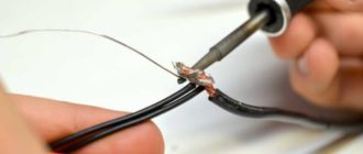
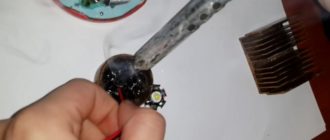
3. Soldering is a method of connecting cables by covering the heated ends of the wires with molten solder, which hardens and provides strength and high electrical conductivity of the connection. This method is used for small cross-section conductors.
Advantages: does not require special skills and specialized equipment compared to welding.
However, it is worth highlighting the disadvantages: a large number of preparatory operations, therefore, high labor intensity.
Before soldering, the conductors are cleaned of insulation and oxide film, then they are tinned, twisted and pressed with pliers. To avoid oxidation of the cleaned surface, fluxes should be applied to the treated areas.
Soldering of small copper wires is carried out using solder tubes filled with rosin or a solution of rosin and alcohol. These solutions are applied to the joint before soldering.
Then you can begin the soldering process: the joint is heated with a soldering iron or torch. Rosin or flux begins to boil, take a little solder onto the soldering iron tip and add it to the soldering zone by pressing the tip against the conductors. The solder spreads and fills the gaps between the wires, thereby creating a connection. If a torch is used, the solder is added to the torch.
After the soldering process is completed and the workplace has cooled, the flux residues must be washed off, the joint dried, coated with a special varnish, and insulated with tape or heat-shrinkable tubing.
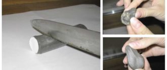
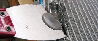
4. Crimping is the process of connecting wires using copper or aluminum sleeves. It is necessary to select a sleeve depending on the size of the “twist” and the cable material (copper or aluminum).
The wires must be cleaned to a metallic shine, bundled/twisted, and then a sleeve is put on them and clamped with special pliers. In this case, the walls of the sleeve are pressed into the conductor conductors and a reliable electrical contact is formed.
Advantages : high reliability; no high demands are placed on the performer regarding his qualifications; independence from the availability of electricity.
Disadvantages: rigid sleeve leads to wire rupture near the sleeve; it is necessary to have a supply of sleeves of various sizes; if the connection is larger than the diameter of the cord, the cable will touch surrounding objects.
How to connect to an inverter
The question of how to properly connect cables to a welding inverter arises when deciding on polarity when welding with direct current: forward or reverse.
The “plus” sign is connected to the electrode holder, the “minus” sign is connected to ground - welding is performed with reverse polarity . In this case, the current moves from the electrode to the workpiece, the metal heats up more than the electrode.
The “minus” sign is connected to the electrode, the “plus” sign is connected to ground, therefore, the polarity is straight. The current flows from the workpiece to the electrode, creating stronger heating of the electrode.
Which polarity should be used depends on several factors: the type of metal; workpiece thickness; electrode type.
More detailed information on how to connect cables to a welding inverter depending on the selected polarity is presented in the corresponding article.
You should also pay special attention to the basic rules for connecting welding cables to inverter-type equipment. These nuances will guarantee a safe and comfortable work process.
Reading this information will help you learn how to connect welding cables to a specific type of equipment.
[ads-pc-3][ads-mob-3]
How to hold it in a holder
The method of fixing the welding cable depends on the type of electrode holder : homemade or purchased (produced by companies of the corresponding profile).
Types of homemade holders and methods of assembling them, their main advantages and disadvantages are discussed in the article “Electrode holder for a welding machine.” This article also presents a method for correctly and securely connecting the cable to the electrode holder.
You should also pay attention to the recommendations of the master , who will help you make a professional, competent holder yourself. For clarity, a video of the assembly of the holder is presented.
To understand how to connect welding cables to the purchased holder , we recommend that you watch the video below. The performer can clearly see that the cable, together with a metal gasket (plate), is inserted into the corresponding hole and securely fixed with a key by tightening the screws.
How to extend the cable on an inverter
Typically, the inverter is equipped with a wire no more than two meters long. Working with such a cable is quite problematic and inconvenient. Therefore, performers often have a question: how to extend the cable on a welding machine ?
Previously, we considered that connecting welding cables should be done in several ways, each of which is used depending on the skills of the performer, the presence or absence of specialized equipment and additional accessories.
Advice! In most cases, the owner of the welder connects the welding cables for the holder and the ground into one longer wire and uses it to connect to the ground . And for the electrode holder, the welder buys a part of the cable of the required length .
It is important to know how to extend a welding cable. The connection of welding cables during extension can be performed using the following methods: welding; soldering; crimping.
It is also worth noting the opinion of some professionals who are against lengthening the conductors . Cables that are too long may adversely affect the performance of the device. In addition, the longer the wire, the greater the current loss, which can negatively affect the quality of welding.
How to choose a welding cable
Equipment of any type will serve its owner for a long time if the wire is selected correctly. When choosing a conductor, you need to pay attention to the following points :
More detailed information is presented in the articles on KG, KOG cables, as well as in the publication on conductors for the inverter.
How to find out the cross section
The main technical characteristics of conductors: cross-section, diameter and other important properties are indicated in catalogs or corresponding descriptions. However, if the contractor does not have the opportunity to familiarize himself with this data, and the question of how to determine the cross-section of the welding cable needs to be answered, then you should remember some recommendations.
There are several ways to determine the cross-section of a conductor. They all boil down to the fact that first you need to calculate the diameter of the core. This can be done using a micrometer or caliper. However, the simplest method, which does not require special accessories, is to use the following method.
The contractor will need to remove the insulation from the conductive core. Then you need to wind the core around a cylindrical object (screwdriver) and use a ruler to measure the total length of the turns, the number of which for accurate calculations should exceed 10. In conclusion: the total length in mm. must be divided by the number of turns. The resulting value will be the diameter of the wire, from which the cross-sectional value can be found.
The contractor can find complete information about the cross-sections of cables of various brands in articles devoted to this topic:
Source: https://WeldElec.com/svarka/post/osnastka/kabel/soedinenie-podklyuchenie-udlinenie/