Soldering BGA components
A distinctive feature of recent electronic technologies is the increasing compaction of the installation of components and microcircuits, which has led to the emergence of BGA-type housings (Ball grid array). This same array is located under the chip body, which allows you to place a large number of pins in a small volume (case).
Such microminiaturization often results in certain inconveniences caused by the difficulty of repairing (soldering) the elements placed in such a housing.
When soldering them, several contact legs and pads are processed at once, located under the bottom of a digital controller or a small chip. You should work with them very carefully; soldering requires specialized equipment, skills, knowledge of technology and professionalism.
BGA repair technology
Soldering BGA chips or reballing is the process of restoring an array of balls on the bottom of the board. In our country, this term has not taken root very well, and the experts themselves simply call this repair process “rolling” the contact balls. The need for this procedure arises in cases where it is necessary to replace a burnt-out microcircuit, having previously unsoldered it from the seat. The procedure itself can be divided into main stages:
- dismantling a faulty microelement after preheating;
- cleaning the carrier board from remnants of old solder;
- rolling of new contact leads;
- installing the component in place.
It should be noted that the quality of soldering differs significantly when working on professional soldering stations and at home using homemade devices. In addition, BGA soldering requires experience, knowledge of the element base, a good eye and high-quality consumables. Having a professional station, repairs will become much easier and will take place in semi-automatic mode.
To work with BGA chips you will need the following tools, materials and accessories:
- soldering station with hot air gun;
- convenient tweezers;
- special solder paste and proprietary flux;
- the required stencil for applying solder paste;
- adhesive tape or braid for removing solder;
Procedure
- For high-quality soldering of BGA packages, preliminary preparation of the footprint (also called the “working area”) is very important. The board to be repaired is placed on a horizontal platform, which has a bottom heating with a local infrared emitter. This emitter is directed to a soldered BGA chip. During lower heating, the station monitors the temperature.
It should not exceed 200°C, since only heating of the solder is required to facilitate the dismantling of the element.
Heating from above is carried out by targeted hot air. Typically, for medium-sized chips the temperature is set in the range of 330–360°C. The procedure takes about a minute. Heating occurs along the edges of the board, excluding the center of the chip. This is required to prevent the crystal from overheating.The time and intensity of air treatment of the microcircuit should be taken into account. Since the arrangement of elements is very dense, there is a possibility of overheating neighboring elements. To do this, they are covered with a special protective film.
- After this, you can dismantle the microcircuit. For this purpose, a chip “lift” is used, which is included in the station kit. This device is necessary to separate the chip being repaired from the printed circuit board.
This is a very important stage. If there is insufficient heating, there is a risk of breaking the tracks.
- The next step is to clean the electronic board and chip from any remaining solder. It is very important here not to damage the solder mask, otherwise the solder may spread along the tracks. For removal, use a soldering iron with a wave-type nozzle. Its use is effective and allows you to achieve the highest quality results.
- Next, BGA soldering technology involves rolling new contact pins onto the chip. It is possible to use ready-made balls. But often the contact pad consists of hundreds of pins. Therefore, in the industrial case, specialized stencil pads are used in which the microcircuit is fixed. When reballing, an important element is high-quality solder paste. When heated, such specimens give an even and smooth ball.
And low-quality pastes break up into a large number of small balls.
- The final procedure for soldering a BGA chip is to install it in place. The element is installed based on the silk-screen printing applied to the board itself or mounting marks. Then the microcircuit is heated with hot air and, due to surface tension forces from the action of molten solder, is fixed at the initial dismantling site, occupying a “comfortable position.”
This completes the repair procedures. The board is washed with flux-off aerosol and tested for functionality.
Read more about the features of BGA mounting:
Source: http://sepco.ru/montage/pajka-bga-komponentov.html
How to re-solder a BGA chip
BGA ( B all G rid A rray) is a matrix of balls. That is, this is a type of microcircuit that has solder balls instead of terminals. There can be thousands of these balls on a chip!
Nowadays, BGA chips are used in microelectronics. They can often be seen on the circuit boards of mobile phones, laptops, and other miniature and complex devices.
In phone repairs, there are a lot of different breakdowns related specifically to microcircuits. These BGA chips may be responsible for certain functions in the phone. For example, one microcircuit may be responsible for power, another for Bluetooth, a third for the network, etc.
Sometimes, when the phone falls, the balls of the BGA chip move away from the phone board and it turns out that the circuit is broken, therefore the phone loses some functions. In order to correct this issue, repairmen either heat the microcircuit so that the solder ball melts and again “grabs” with the contact pad on the phone board, or they completely dismantle the microcircuit and “roll” new balls using a stencil.
The process of rolling balls onto a BGA chip is called reballing. In the Russian expanses this term has not taken root and in our country it is simply called “rolling”.
Our guinea pig will be a mobile phone board.
To make it easier to solder “those black squares” on the board, we will use an infrared preheater or popularly “bottom heating”. We set the temperature on it to 200 degrees Celsius and go drink tea. After 5-7 minutes we begin to fend off our patient.
Let's focus on the BGA chip, which is simpler.
Now we need to prepare the tools and chemistry for soldering. We can't do without stencils for various BGA chips. Those who are seriously involved in repairing phones and computer equipment know how important this is. The photo below shows the entire set of stencils for a mobile phone repairman.
Stencils are used to “roll” new balls onto prepared BGA chips. There are universal stencils, that is, for any BGA chips. There are also specialized stencils for each microcircuit. At the very top of the photo we see specialized stencils. Bottom left - universal. If you choose the right pitch on the chip, you can easily roll balls onto any of them.
In order to reball a BGA chip, we also need the following simple tools and consumables:
Here is the familiar Flux-off to all of you. You can read more about it and other chemistry in the article Chemistry for an electronics engineer. Flus Plus, Solder Plus solder paste (gray mass in a syringe with a blue cap) is considered the best solder paste, unlike other pastes.
The balls with it turn out like factory ones. The price for this paste is expensive, but it's worth it. Well, of course, among all the other junk there are also price tags (buy them so that they are very sticky) and a simple toothbrush.
We will need all these tools to reball a simple BGA chip.
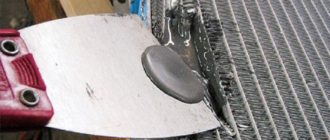
In order not to burn the elements located nearby, we will cover them with thermal tape.
Lubricate the microcircuit generously around the perimeter with FlusPlus flux
And we begin to warm up our BGA with a hairdryer over the entire area
This is where the most crucial moment comes when soldering such a microcircuit. Try to heat with an air flow slightly less than average. Raise the temperature literally a couple of degrees. Doesn't unsolder? Add a little heat, and most importantly DO NOT RUSH! A minute, two, three does not boil off, add heat.
Some repairmen like to chatter “hahaha, I can unsolder the BGA in a matter of seconds!” They unsolder, then they unsolder, but at the same time they do not understand how much stress the soldered element and the printed circuit board receive, not to mention the nearby elements.
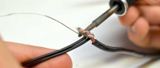
I repeat once again, TAKE YOUR TIME, TRAIN ON CORDS. DO NOT HURRY to tear off an unsoldered microcircuit, it will backfire on you, because you will tear off all the dimes under the microcircuit! Use special devices to lift microcircuits.
I found them on Ali via this link.
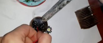
And so we heat our microcircuit with a hairdryer
and at the same time we check it using a chip extractor. I wrote about him in this article.
The microcircuit, ready for lifting, should “float” on the molten balls, well, let’s say, like a piece of meat on jellied meat. We lightly touch the microcircuit. If it moves and returns to its place, then carefully lift it with the help of antennae (in the photo above). If you don’t have such a device, then you can use tweezers. But be extremely careful! Don't use force!
Currently, there are also vacuum tweezers for microcircuits of this kind. There are manual vacuum tweezers, the operating principle of which is the same as that of the Desalt Pump
and there are also electric ones
I had hand tweezers. To be honest, she's still a piece of shit. Hardcore repairmen use an electric vacuum cleaner. One has only to bring such tweezers closer to the BGA chip, which is already “floating” on the molten balls of solder, and it immediately picks it up with its Velcro.
According to reviews, electric vacuum tweezers are very convenient, but I still haven’t had a chance to use them. In short, if you decide to, go electric.
But let’s return to our microcircuit. With a tiny push, I make sure that the balls are really melted, and with a smooth upward movement I turn the BGA chip over. If there are many elements nearby, then it would be ideal to use vacuum electric tweezers or tweezers with curved jaws.
Hurray, we did it! Now we will practice soldering it back :-).
Now the most difficult process begins - the process of rolling the balls and soldering the microcircuit back. If you haven't forgotten, this is called rolling . To do this, we must prepare a place on the printed circuit board. Remove any solder that remains there. We lubricate the whole thing with flux:
and start removing all the solder from there using good old copper braiding. I would recommend the Goot wick brand. This copper braid has proven itself very well.
If the distance between the balls is very small, then use copper braiding. If the distance is large, then some repairmen do not resort to copper braiding, but take a fat drop of solder and, with the help of this drop, collect all the solder from the patches. The process of removing solder from BGA patches is a very delicate process. It is best to increase the temperature of the soldering iron tip by 10-15 degrees. It also happens that the copper braid does not have time to warm up and pulls out spots behind it. Be very careful.
Next, we spray Flux-off there to clean our place for the microcircuit from carbon deposits and excess flux.
and sand it using a simple toothbrush, or even better, a cotton swab dipped in Flux-Off.
It turned out something like this:
If you look closely, you can see that I still tore off some of the spots (there are black circles at the bottom of the microcircuit, instead of tin ones) But! Don't be upset, they are, as they say, single. That is, they are not electrically connected in any way to the phone board and are made simply to securely attach the microcircuit.
Next, we take our BGA and remove all the excess solder balls. As a result, it should look like this:
And now the most interesting and complex process begins - rolling balls onto the BGA chip. We put the prepared microcircuit on the price tag:
We find a stencil with the same pitch of the balls and attach the microcircuit to the bottom of the stencil using the price tag. Using your finger, rub Solder Plus solder paste into the holes of the stencil. It should look something like this:
We hold the tweezers with one hand and a hair dryer in the other and begin to fry at a temperature of approximately 320 degrees on a very low flow over the entire area where we rubbed the paste. I wasn’t able to hold the camera, hair dryer and tweezers in both hands at once, so there weren’t enough photos.
We remove the finished microcircuit from the stencil and lubricate it with a little flux. Next, heat with a hairdryer until the balls melt. We need this so that the balls fall evenly into place.
Let's see what we got as a result:
Damn, it's a little sloppy. Some balls are a little larger, others a little smaller. But all the same, this will not interfere at all when soldering this chip back onto the board.
We lightly lubricate the nickels with flux and put the microcircuit in its original place. Align the edges of the microcircuit on both sides according to the marks. There is only one mark in the photo below. Another mark is opposite it diagonally.
And using a very small air flow from a hairdryer with a temperature of 350-360 degrees, we seal our little thing. If sealed correctly, it should fit normally on its own, even if we are slightly skewed.
Where is the key for the BGA chip?
Let's look at the moment when we suddenly forgot how to install the microcircuit. I think all repairmen had this problem ;-). Let's take a closer look at our little thing through an electron microscope. In the red rectangle we see a circle. This is the so-called “key” from where all the BGA ball pins are counted.
Well, if you forgot how the microcircuit was installed on the phone board, then look for a circuit diagram for the phone (there are a dime a dozen of them on the Internet), in this case Nokia 3110C, and look at the arrangement of the elements.
Oops! Now we have found out which direction the key should be located!
For those who are too lazy to buy solder paste (it is very expensive), it will be easier to purchase ready-made balls and insert them into the holes of the BGA stencil.
I found a whole set of them on Ali, for example here.
Conclusion
The future of electronics belongs to BGA chips. microBGA technology is also gaining great popularity, where the distance between the pins is even smaller! Not everyone will undertake to solder such microcircuits). In the repair industry, the future lies in modular repairs.
Basically, now it all comes down to purchasing a separate module or an entire device. It’s not for nothing that smartphones are made monolithic, where both the display and the touchscreen already come together in one package.
Some microcircuits, and indeed entire boards, are filled with a compound that makes it impossible to replace radio elements and microcircuits.
Source: https://www.RusElectronic.com/pajka-bga-mikroskhjem/
BGA soldering of cases at home
In modern electronics, there is a steady trend towards increasingly dense installations. The consequence of this was the emergence of BGA packages. We will consider soldering these structures at home in the framework of this article.
general information
Initially, many pins were placed under the chip body. Thanks to this, they were placed in a small area. This allows you to save time and create ever smaller devices. But the presence of such an approach during manufacturing results in inconvenience during the repair of electronic equipment in a BGA package. Soldering in this case should be as careful as possible and be carried out exactly according to technology.
What do you need for work?
You need to stock up:
- A soldering station with a hot air gun.
- With tweezers.
- Solder paste.
- Electrical tape.
- Braid for removing solder.
- Flux (preferably pine).
- A stencil (to apply solder paste to the chip) or a spatula (but it’s better to stick with the first option).
Soldering BGA packages is not difficult. But for it to be successfully implemented, it is necessary to prepare the work area. Also, to be able to repeat the actions described in the article, it is necessary to talk about the features. Then the technology for soldering microcircuits in a BGA package will not be difficult (if you understand the process).
When explaining what the technology for soldering BGA packages is, it is necessary to note the conditions for the possibility of full repetition. Thus, Chinese-made stencils were used. Their peculiarity is that here several chips are assembled on one large workpiece. Due to this, when heated, the stencil begins to bend.
The large size of the panel means that when heated, it takes away a significant amount of heat (that is, a radiator effect occurs). Because of this, it takes more time to warm up the chip (which negatively affects its performance). Also, such stencils are made using chemical etching. Therefore, the paste is not applied as easily as on laser-cut samples.
It would be good if there were thermal seams. This will prevent the stencils from bending as they heat up. And finally, it should be noted that products made using laser cutting provide high accuracy (deviation does not exceed 5 microns). And thanks to this, you can simply and conveniently use the design for its intended purpose.
This concludes the introduction, and we will study what the technology for soldering BGA cases at home involves.
https://www.youtube.com/watch?v=0V4cfUkugJ4
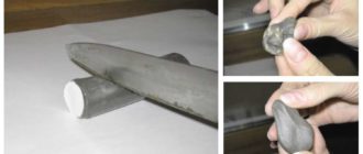
Before you begin to solder the microcircuit, you need to apply strokes along the edge of its body. This must be done if there is no silk-screen printing that shows the position of the electronic component. This must be done to make it easier to later install the chip back on the board. The hairdryer should generate air with heat of 320-350 degrees Celsius.
In this case, the air speed should be minimal (otherwise you will have to solder back the small items placed nearby). The hair dryer should be held so that it is perpendicular to the board. Warm it up in this way for about a minute. Moreover, the air should be directed not to the center, but along the perimeter (edges) of the board. This is necessary in order to avoid overheating of the crystal.
Memory is especially sensitive to this. Then you should pry the chip by one edge and lift it above the board. However, you should not try to tear with all your might. After all, if the solder has not been completely melted, then there is a risk of tearing off the tracks. Sometimes, when applying flux and heating it, the solder will begin to form balls. In this case, their size will be uneven.
And soldering microcircuits in a BGA package will be unsuccessful.
Cleaning
We apply alcohol rosin, heat it and get the collected garbage. Please note that such a mechanism should under no circumstances be used when working with soldering. This is due to the low specific coefficient. Then you should wash the work area and you will have a good place. Then you should inspect the condition of the conclusions and assess whether it will be possible to install them in their old place. If the answer is negative, they should be replaced.
Therefore, you should clean the boards and chips from old solder. There is also the possibility that the “nickel” on the board will be torn off (when using braiding). In this case, a simple soldering iron can be of great help. Although some people use braid and hair dryer together. When performing manipulations, you should monitor the integrity of the solder mask. If it is damaged, the solder will spread along the tracks. And then BGA soldering will fail.
Rolling new balls
You can use already prepared blanks. In this case, they simply need to be laid out on the contact pads and melted. But this is only suitable for a small number of pins (can you imagine a microcircuit with 250 “legs”?). Therefore, stencil technology is used as an easier method.
Thanks to her, work is done faster and with the same quality. The important thing here is to use quality solder paste. It will immediately turn into a shiny, smooth ball. A low-quality specimen will disintegrate into a large number of small round “shards”. And in this case, it’s not even a fact that heating to 400 degrees and mixing with flux will help.
For ease of operation, the microcircuit is fixed in a stencil. Solder paste is then applied using a spatula (although you can use your finger). Then, holding the stencil with tweezers, you need to melt the paste. The temperature of the hair dryer should not exceed 300 degrees Celsius. In this case, the device itself must be perpendicular to the paste.
The stencil should be maintained until the solder has completely cured. After this, you can remove the fastening insulating tape and use a hairdryer, which will heat the air to 150 degrees Celsius, gently heat it until the flux begins to melt. After this, you can disconnect the microcircuit from the stencil. The end result will be smooth balls.
The microcircuit is completely ready to be installed on the board. As you can see, soldering BGA packages is not difficult at home.
Fasteners
Previously it was recommended to make strokes. If this advice was not taken into account, then positioning should be done as follows:
- Turn the chip over so that the pins are facing up.
- Apply the edge to the nickels so that they coincide with the balls.
- We fix where the edges of the microcircuit should be (for this you can apply small scratches with a needle).
- We fix one side first, then perpendicular to it. Thus, two scratches will be enough.
- We place the microcircuit according to the designations and try to catch the nickels at the maximum height with the balls by touch.
- Heat the work area until the solder is molten. If the previous steps were followed accurately, then the microcircuit should fall into place without any problems. The force of surface tension possessed by the solder will help her with this. In this case, it is necessary to apply just a little flux.
How to solder (change) surface mount BGA chips?
page » How to solder (change) surface mount BGA chips?
Almost all modern electronics, including tablets, laptops, smartphones, etc., contain surface-mount chips on their motherboards. The design of such microcircuits differs in that instead of the classic wire leads, it contains a ball array.
That is, a certain number of metal contact points, which in fact represent pieces of solder in the form of small balls. Such balls, accordingly, cannot be inserted into traditional holes on the board, but BGA chips can be soldered to mounting pads. This is surface mounting.
Let's look at how to solder BGA chips, as well as the necessary equipment for the job.
Replacing surface mount chips
It would seem that surface mount integrated circuit technology requires a unique mechanical approach. Looking at such a chip installed on the motherboard of a laptop or other equipment, it is difficult to imagine how, for example, you can replace a chip at home if it fails. However, as practice shows, home repairs with BGA (Ball Grid Array) replacement are quite possible.
EVERYTHING FOR BGA
How to solder a microcircuit constructed using BGA technology - a chip that is simply applied to the surface of a printed circuit board? It turns out it's not difficult at all
Of course, you need to have some skills in repairing electronic equipment and soldering skills in microcircuits, in particular. You will also need a certain instrumental and material base:
- electric soldering gun,
- auxiliary infrared heater,
- miniature vacuum pump with suction cup,
- special flux,
- electric soldering iron,
- other auxiliary tool.
In addition to the entire designated material base, an important component in the soldering of surface-mount BGA microcircuits is a special flux - a paste-like substance.
What is flux for soldering BGA chips?
In fact, soldering flux for surface-mount microcircuits is a chemical (acidic) compound, thanks to which high-quality “cleaning” of soldering areas is achieved. There are two types of paste-like (gel-like) fluxes:
- Fluxes requiring subsequent cleaning.
- Fluxes that do not require cleaning.
Meanwhile, in any case, you should still resort to cleaning the board from flux residues after completing all work, thereby preventing possible destruction of the PCB structure in the future. It should be noted: almost all fluxes intended for soldering surface-mount microcircuits (BGA) can be washed quite easily.
BGA PASTE
Flux, a substance used when soldering surface-mount chips, looks like this consistency.
Typically packaged in plastic syringes for ease of use
The commercial market offers a wide selection of materials of this kind for working with surface-mount microcircuits.
In particular, a rich assortment is presented on the well-known Chinese portal Aliexpress. Moreover, the prices of Chinese goods are significantly lower than branded European ones, and the quality is quite consistent.
If desired, it is possible to make flux yourself using a certain set of substances:
- glycerin (a mixture of glycerin and aspirin),
- acetic acid (ammonia),
- alcohol solution of rosin,
- wax.
However, it is preferable to use a ready-made commercial product.
Infrared motherboard heater
Additional heaters, for example, an infrared desktop device with automatic temperature setting, are used to warm up the motherboard from the bottom side relative to the installation of the BGA chip.
In this way, uniform heating is achieved during the process of soldering (replacing) a surface-mounted BGA microcircuit, and deformation of the motherboard PCB structure is eliminated.
HEATER
The Chinese portal Aliexpress is full of such ceramic panels of infrared radiation, which are proposed to be used under the tool for lower heating of electronic boards
However, digital infrared heaters are quite expensive (from 5,000 rubles), so for home use (individual, not large-scale repairs) it is more logical to use simple ceramic infrared plates for soldering BGA microcircuits.
An upper heating tool is used together with bottom heating. In particular, the traditional tool here is a soldering iron - a modern-style electric soldering iron, “sharpened” for soldering (desoldering) miniature elements of electronic boards.
Electric soldering gun for surface mount chips
This type of soldering tool differs from a traditional soldering iron with a metal tip in that in this case a working tip is not used. Instead of a working tip, the required temperature background in the soldering areas is provided by a flow of heated air. Accordingly, the design of a soldering gun should be considered a kind of air pump, equipped with a heating and control system.
BGA SOLDERING IRON
One of the many design options for a soldering station that supports the use of a conventional soldering iron with a tip and the operation of a soldering gun
There are soldering guns of various designs and operating capacities.
Factory-made structures usually have functions for controlling the strength of the air flow, the temperature of the outgoing air, and allow visual monitoring of parameters.
At the same time, it is possible to make a completely tolerable soldering iron from an ordinary electric soldering iron by performing some modernization of the design.
Vacuum pump with suction cup for BGA chips
This rather original tool is desirable for use when it comes to soldering (desoldering) surface mount BGA type microcircuits. In fact, to work with other electronic components of modern technology, a vacuum suction cup may also be required quite often.
Typically, soldering stations of industrial (commercial) production are already equipped with this functionality. The good thing about this tool is that it allows you to carefully dismantle a BGA chip that has been heated to the point of dismantling, without affecting nearby components. However, let's get down to business - how to unsolder and replace a faulty BGA chip on the motherboard.
Do-it-yourself BGA chip replacement at home
So, the home technician has at his disposal a laptop motherboard, where during the diagnostic process a faulty surface-mount BGA chip was discovered, in particular, a chip from one of the bridges of the computer board. It is necessary to dismantle the BGA surface-mount chip, and instead of the dismantled chip, it is necessary to install another - serviceable component.
STENCIL
The process of replacing a faulty surface mount chip on a laptop motherboard. You will need information on removing the board from the device body.
First, the motherboard is removed from the laptop case, for which you should refer to the service instructions of the specific tablet computer manufacturer. In each individual case, the procedure for dismantling the motherboard may differ radically.
Preparing the motherboard for repair
The removed laptop circuit board is installed above the infrared quartz heater in such a way that the maximum heat flow falls on the area where the chip is being soldered.
The next step is to treat the surface-mount chip with a special flux. The dismantled chip, usually rectangular (square) in shape, is processed by uniformly applying a small amount of gel-like flux around the perimeter.
FLUXES
Treatment of the dismantled BGA chip with a special flux - coating the four sides of the chip body with a gel-like substance using a plastic syringe
Further according to the technological procedure:
- turn on the infrared bottom heater,
- wait for the applied flux to melt,
- at a temperature of 250-300ºC, remove the corner plastic clamps of the chip,
- After reaching a temperature of 300-325ºC, use a soldering iron.
Top heating of the microcircuit with a soldering hair dryer
A soldering gun is used to heat a surface-mounted BGA chip along the top side of the chip. If a soldering station with a temperature controller is used, the parameters are usually set to the range of 350-400ºC. Evenly directing the air flow of the hair dryer to the area of the microcircuit, wait for the tin to completely melt.
The moment of complete melting can be determined by periodically checking the condition of the chip. Once the chip begins to “wiggle” in place, it’s time to use the suction cup tool.
Using a suction cup tool, they cling to the center of the microcircuit body and simply remove the chip from its installation site. When the tin is completely melted, this operation does not cause any difficulties.
Preparing the landing area of the microcircuit on the board
After removing the faulty surface mount IC (BGA), you should prepare the installation site. Preparation consists of “cleaning” the contact pads for the tin “balls” of the new microcircuit. For this procedure, it is enough to use a regular soldering iron with a tip that is well sharpened and has smooth working edges.
BALLOONS
The procedure for stripping a surface mount chip (BGA) using a conventional soldering iron. The process takes no more than one or two minutes
The “stripping” area is first treated with a small amount of flux for BGA soldering and then the remaining tin is carefully removed with a soldering iron tip.
Radio amateurs use different methods for cleaning, including the option when using a cable braid. But the practice of an established radio amateur shows that one soldering iron, patience and accuracy are quite enough.
Installing and soldering a new serviceable component
At the next stage, the BGA chip prepared for replacement should be placed in place of the dismantled chip. In this case, it is necessary to correspond to the markers (lines) on the electronic board, including the “key” marker, which indicates the correct position of the chip according to the working contacts.
Next, the infrared quartz bottom heating heater is turned on, and the board is heated until the flux melts. Turn on the soldering gun and heat the upper area of the surface-mount microcircuit to a temperature of 350-400ºC.
That's all. A new BGA type microcircuit is installed to replace the faulty one. The laptop motherboard is ready for use. More details in the video below.
Master class on desoldering (soldering) BGA chips
A video demonstration of the process of removing a faulty chip and then installing a working BGA chip as a replacement. Repairing a laptop motherboard at home with all the details:
The final touch on soldering BGA chips
As the text above shows, the procedure for replacing (resoldering) surface-mount microcircuits on various electronic boards is a completely solvable task. Moreover, this work can be done at home, provided you have the appropriate tools. Having the skills to replace BGA chips opens up wide opportunities for organizing your own business repairing household electronic appliances.
Source: https://zetsila.ru/%D0%BA%D0%B0%D0%BA-%D0%BF%D0%B0%D1%8F%D1%82%D1%8C-%D0%BC%D0 %B8%D0%BA%D1%80%D0%BE%D1%81%D1%85%D0%B5%D0%BC%D1%8B-bga/
Bottom heating temperature when soldering bga
Instrument electronics is developing simultaneously with general electronics, which results in the continuous improvement of the tools used during repairs.
One of these tools was a soldering gun. Many modern household appliances, such as TVs, tablets, laptops, can only be repaired with its help.
What is needed for work
A soldering gun, also called a hot-air soldering station, is a multi-component tool with a large number of functions for repairing modern devices. It allows you to solder SMD components, capacitors, LEDs and other parts. The same applies to BGA-type chips, which make installation more dense. Today, almost every electronic component in modern devices is made in this way.
To solder SMD components, you need the following materials and devices:
- actually, the hair dryer itself;
- attachments for it;
- flux with solder paste;
- copper braid;
- some kind of device for prying up parts (tweezers, for example);
- medium-soft brush;
- lens;
- a soldering iron with a thinner tip compared to a standard one;
- stencil for “rolling”.
To work competently with a soldering gun means to be careful, have angelic patience, and be extremely careful.
Sequence of actions using the example of an SMD component
Let’s say that on the working printing surface of the electronic unit being repaired there is a burnt-out SMD box that needs to be dismantled. To remove it and install a new one, you need to select a compact nozzle for the hair dryer and prepare flux.
The temperature regime on the soldering hair dryer is set within 345-350 degrees using a regulator. Then they apply flux to the part to be replaced, and begin to slowly “warm up”.
The air pressure during the process should not be too strong, otherwise there is a risk of blowing away nearby elements. The culprit of the breakdown continues to be heated until the solder begins to melt, which will be immediately noticeable.
It may take about three minutes to warm up, and this is normal, there is no need to rush. If the solder persists for a long time, you need to add 5 degrees.
After the solder has liquefied, carefully dismantle the SMD part. During the process, it is important not to knock down the neighboring components, since they have probably lost stability due to the melting of the solder holding them in place.
Upon completion of the operation, the copper braid must be used to clean the “spots” (contact pads), then provide small bumps in the same places with solder paste or solder.
A serviceable smd is placed in the old place with a minimum amount of flux. Heat the part with a soldering hair dryer until the solder shines brightly, spreading over each of the contacts.
Features of working with BGA chips
When soldering BGA type microcircuits, the same temperature range is selected from 345 to 350 degrees, ensuring moderate air pressure to prevent blowing off the “neighbors”. During operation, the soldering gun should be held at an angle of 90 degrees with respect to the board. To avoid failure of the chip, you should not heat it only in the center; it is better to go around the mounting element around the perimeter.
After 1-3 minutes have elapsed, you can try to slightly lift the chip above the board using tweezers. If the chip does not budge, the solder is still hard. To avoid damage to the conductive paths of the board, you need to use the regulator on the hair dryer to “throw on top” 5 degrees of temperature and continue heating.
Heating from below
This technique is not only useful when working with a soldering gun, but also increases the convenience of soldering.
The board is secured with a clamp, the temperature is set to 200 degrees and warmed up for five minutes, after which they begin to work as usual.
Using thermal tape, you can shield nearby elements.
After removing the chip, the contacts are cleaned with the above braid. Do the same with the board.
All procedures must be carried out carefully to prevent damage to the circuit. If you don't have copper braid on hand, you can remove the solder using a soldering iron with a thin tip.
Reballing procedure
To carry out reballing, the chip is placed in a stencil and secured with specialized electrical tape. Apply solder paste on the back side with a finger or spatula, then set the hair dryer to a temperature of about 300 degrees and begin to warm it up. After the characteristic shine from the molten solder paste appears, allow the solder to cool completely.
To free the stencil from the chip, remove the electrical tape and heat the stencil to approximately 150 degrees; at the end of the procedure, the part should be free. It happens that it is impossible to immediately remove a part from a Chinese stencil, so it may be necessary to carefully hook it.
During reverse soldering of the microcircuits, the risks are assessed and the chip is laid out the required number of times to ensure an exact match of the heels and balls. Then they set the temperature on a soldering hair dryer to 330 to 350 degrees and heat until the melted solder allows the chip to fall into place on its own.
Source: https://steelfactoryrus.com/temperatura-nizhnego-podogreva-pri-payke-bga/
Choosing a flux for soldering BGA chips
In soldering processes, an important role is played by fluxes, that is, substances that can remove oxide films formed as a result of a thermochemical reaction from the surfaces of the parts being joined. The quality of the process depends on their choice. With the development of electronics, the requirements for fluxes for bga soldering have increased.
Requirements for fluxes for microcircuits
In the manufacture of microcircuits, special printed circuit boards are used as a supporting element. The material for their production is fiberglass - a layered heat-resistant plastic that is covered with copper foil. The pins of the chips are connected to the copper by soldering.
Using flux for soldering BGA chips
The flux used for such delicate work must ensure good contact between the soldering elements. The presence of contaminants on them can impair the wettability and thermal conductivity of the surface. Therefore, they should first be cleaned using special solvents.
Today, the market offers a huge selection of fluxes for bga soldering. They must meet the following requirements:
- have a melting point lower than that of solder;
- do not enter into a chemical reaction with the solder material;
- have high fluidity and well wet the surfaces of the elements being connected;
- have a low specific gravity;
- dissolve fatty and oxide films;
- effectively wash off from the treated surface;
- prevent corrosive activity;
- distinguished by ease and convenience of application.
Only by ensuring that all these conditions are met can a reliable connection of soldering elements be obtained. There are also special compositions on sale for high-quality cleaning of boards from flux. But the best fluxes for soldering bga microcircuits are those that do not require rinsing.
Types of modern fluxes
Modern industry produces two main types of fluxes. The first group of reagents includes chemically active substances - hydrochloric acid and some of its salts.
They dissolve oxide films and fats well, promoting a strong connection of elements, but require effective washing. If at least a small part of the active flux remains at the soldering site, it will gradually destroy both the metal and the PCB.
In addition, their vapors are very toxic, so safety precautions should be observed when working.
The second group of substances are chemically inert compounds, for example, rosin or wax. Basically, these are organic compounds that dissolve fats well, but to a lesser extent - oxides. But they do not allow subsequent corrosion, which is very important. Recently, LTI fluxes have been used, created on the basis of ethanol and rosin with the addition of small quantities of triethanolamine, salicylic acid and other substances.
Most popular reagents
The most common fluxes include:
- pine rosin - for its low cost and low chemical activity;
- orthophosphoric acid - it prevents further destruction of the surfaces being joined, forming an oxide film on them;
- LTI-120 – contains rosin with additives, does not require washing;
- flux-gel for soldering bga, made in the form of a paste, is easily washed off without leaving residue;
- active flux, which contains 90% glycerin and 5% salicylic acid, requires good rinsing;
- neutral type of solder fat.
No-clean materials
When choosing which flux is best for soldering bga chips, it is advisable to give preference to those reagents that do not require subsequent cleaning of the board. Well-known microelectronics manufacturers have long used No-Clean in liquid or gel form.
Fluxes for soldering BGA chips
INTERFLUX fluxes are considered one of the best soldering materials on the market. For example, composition IF8001 is used when it is necessary to quickly and efficiently repair an individual element on a microcircuit. The substance is activated already at 12 degrees, that is, before soldering begins, ensuring a clean surface. Directly during the process it evaporates by more than 90%. The remaining solid residue is non-toxic and slightly alkaline, protecting the board from chemical activity.
Source: https://svarkaipayka.ru/material/flyus-dlya-payki/vyibor-flyusa-dlya-bga-mikroshem.html
All about BGA chip soldering: step-by-step instructions and soldering techniques
Category: Soldering, Articles 02.11.2018 · : 0 · Reading time: 5 min · Views:
BGA is a type of chip package. The microcircuit is soldered to the board using balls. This reduces the area of the board and improves the overall layout. The main malfunction in this case is the so-called chip removal from the board. Let's talk in more detail about the main methods of knurling, stencils and the soldering process.
What are BGA chips
Depending on the purpose and device, microcircuits come in different sizes, which in turn affects the diameter and pitch of the balls. For example, a bridge from a computer motherboard and a processor from a smartphone differ enormously (even less are the balls from the processor to the substrate).
Also, BGA chips are often coated with a compound for cooling, protection from moisture and mechanical stress, but this makes it much more difficult to replace such a chip.
What types of stencils are there?
Stencils are very different. BGA soldering is varied. The pitch between the contacts, the diameters of the balls and their unique arrangement. There are universal ones that do not have a “pattern” and can be used to roll different microcircuits.
Universal stencils are only suitable if the pitch and diameter of the balls match and there is no chaotic arrangement. That is, the contacts should be straight, but if the contacts are slightly not in a straight line, then such stencils will not be of much help.
Specialized ones have a pattern, and they are easier to apply balls with.
However, the required stencil is not always available and must be ordered separately. There are also 3D stencils that are very convenient to attach. There are both single stencils and all on one sheet at once.
Solder
There are two ways to roll balls. The first is solder paste. This paste contains flux and microscopic solder balls. One of the advantages of the paste is that it is convenient to apply, does not require much space and can be used on any stencil.
In addition, using the paste you can restore contacts and the paste is more convenient to apply.
Disadvantages - the balls are not the same size, the paste dries out over time (you can, of course, dilute it with another flux, but it will no longer have the same properties) and the impossibility of manual rolling without a stencil.
In addition, when rolling with paste, the requirements for the quality of the stencil are much higher.
The second is ready-made balls. The advantages are more convenient knurling, the balls are all the same, excess balls from the universal stencil can be reused, manual knurling is possible, the requirements for the quality of the stencil are lower. Disadvantages: cost-effectiveness (you need to buy many balls of different diameters) and the process of applying the balls itself.
Rolling balls
When rolling balls, you must use a clean and even stencil (especially when soldering with paste). The microcircuit itself is cleaned of old balls, but not at the root, to make it easier to install it on the stencil.
If knurling is done with balls, then you must first apply flux evenly to the microcircuit, only then place the stencil. Next, the stencil must be installed evenly so that all contact pads can be seen through the stencil, without distortion.
It is best to secure the chip with aluminum tape because of its good density.
BGA CPU soldering step by step
The tablet booted every other time.
When pressure is applied to the processor, the loading screen goes through, but the charging percentage is 0%. Changing the battery and trying to flash the device did not lead to anything. Engineer mode is also not available. There is a lot of loose debris near the processor; it is better to cover it with thick aluminum tape so as not to accidentally blow it away.
Processor desoldering
Be sure to take a photo of the soldering area so that there are no problems determining which side the key is located. First, the soldering area is heated to 100 - 150 °C at maximum air flow. After about a minute, gradually increase the temperature. 200 °C, 250 °C and ceiling 310 °C - 320 °C.
At temperatures above 250, we try to gently rock the processor with tweezers. If it stands still, then wait some more (or increase the temperature, but not more than 320 °C). When the processor wobbles from one touch of tweezers, then it’s time to remove it.
In this case, everything is protected with foil, so the risk of touching the crumbs is minimal, so you can use tweezers to fold it onto the board.
Removing the solder
It is better not to use braid to avoid damaging the mask. Using a soldering iron and a little solder on the tip (to dilute the solder with what is on the board), we move along the pads with light and not sudden movements. Naturally, before this we apply flux to the board. The same procedure applies to the processor itself. It is important not to overheat it and not rip off the coin.
By the way, after desoldering it was discovered that on several contacts there was a detachment of the processor from the board. Since the copper layer was intact on the processor, we were able to re-tin the broken contacts with the balls.
Ball rolling and installation
Processor BGA soldering.
Using solder paste and a stencil, we apply new balls to the processor. Soldering temperature is much lower.
180 °C - 200 °C. We fix the processor to the stencil using the same aluminum tape. After the stencil, clean the processor and apply a little flux. Then we heat it again so that the balls fall into place more accurately and melt better. Clean after this procedure.
Then, before installation, apply flux to the board in an even layer. Using spatulas or toothpicks, distribute it evenly so that all contacts are well soldered and the processor does not float.
We place the processor according to the key and position its edges. Since there is a lot of tape around, this won’t be too difficult. After this, we also first heat the board at 100 - 150 °C, then increase it to 200 °C - 230 °C and carefully try to touch it with tweezers to make sure whether the solder has melted or not. If you do this abruptly, you will have to repeat everything again because... the balls stick together.
After soldering, remove the tape and it is best not to clean the board at all. There is very little air under the BGA chips, and therefore, once the cleaning agent gets there, it is very difficult to completely remove it. Of course, you can try to “evaporate” the flux at 100 °C, but if you have a good and no-clean flux, then there is no need to worry.
The tablet started to turn on without any pressure on the processor, but after booting it turned off at 0%. Only now can you enter engineer mode and try to reset the tablet. After the reset, the device turned on normally and shows the charging process, the remainder and stopped turning off.
Now you need to carefully check all its functions. Camera, sound, microphone, Wi-Fi, touchscreen.
Source: https://tyt-sxemi.ru/bga-pajka/
Soldering BGA chips
Components in BGA (Ball Grid Array) packages represent the most complex element in the classical surface-mount technology and raise the maximum number of questions among craftsmen and users. There are a large number of defects that arise during soldering and appear during operation of the laptop, which provides a good prerequisite for contacting a service that knows how to work with BGA components.
Download article – Focused infrared soldering.pdf
When replacing a laptop's graphics card or bridge, solder paste reflow is the primary method for forming solder joints. When used correctly, reflow soldering provides high yield and high reliability.
In our service center, the guarantee for such types of work is six months . Among all the conditions of this process, the soldering temperature profile is one of the most important points that determines the level of defects during soldering.
Factors influencing the formation of the temperature profile of BGA soldering:
- Components;
- printed circuit boards (in this case, a laptop motherboard);
- solder paste/equipment;
- master's experience;
- defects when soldering microcircuits.
As we can see, there are quite a lot of factors influencing the formation of TC: poor wetting / spread of paste / formation of bridges / “gravestone” effect / “cold soldering” / formation of solder beads / capillary wicking of solder / deformation of solder joints / lack of contact / cracking of the component , as well as delamination of solder or pad due to internal stresses / formation of voids.
Soldering temperature profile stages
Classification temperature profile recommended by IPC/JEDEC J-STD-020C standard
Pre-heating stage
This step reduces thermal shock to electronic components and printed circuit boards. The preheating process evaporates the solvent from the solder paste.
It is recommended to preheat to a temperature of 95-130 °C, the rate of temperature increase is 0.5-1 °C/s, directly during the bga soldering process. Before soldering, the laptop motherboard must first be heated (“dried”) at a temperature of 100 degrees for two to three hours.
Excessive preheating rates may cause the solvent in the solder paste to evaporate prematurely.
Stabilization stage
The stabilization stage allows you to activate the fluxing component and remove excess moisture from the solder paste. The temperature rise at this stage occurs very slowly.
The stabilization stage is also called the temperature equalization stage because this stage must ensure that all components on the board are heated to the same temperature, thereby preventing damage to components due to thermal shock. Maximum flux activation occurs at a temperature of about 150 °C.
The recommended stabilization time of 30 s is considered sufficient. At the end of the stabilization zone, the temperature usually reaches 150-170 °C. Reducing the stabilization time can lead to cold solder defects and the tombstone effect. We pay attention to the use of high-quality flux; cheap traditional flux will not work.
At this stage, great attention must be paid to the heating zone so that nearby components are not damaged. For example, if there is a video card next to the bridge, then uneven heating will lead to soldering sticking on the adjacent element.
Reflow stage
During the reflow stage, the temperature rises until the solder paste melts and a solder joint is formed. To form a reliable solder joint, the maximum soldering temperature should be 30-40 °C higher than the melting point of the solder paste and be 235-260 °C (on the board).
The time during which the printed circuit board is above the melting point (205-220 ° C) should be in the range of 30-90 s, preferably no more than 60 s. The rate of temperature increase in the melting zone should be 2-4 °C/s. It is almost impossible to achieve such temperatures in a certain time using a hair dryer.
Therefore, we categorically do not recommend soldering dga at home. The only thing that can be achieved is tearing off and deforming the tracks under the chip.
Note: Low soldering temperatures provide poor wettability, especially for components with poor solderability. The minimum temperature required for the formation of an intermetallic compound when using lead-free solders is 235-260 °C. Excessive temperature rise can destroy the chip and also peel off the motherboard.
Cooling stage
To ensure maximum strength of solder joints, the cooling rate should tend to the maximum permissible. Recommended cooling rate is 3-4 °C/s to a temperature below 130 °C.
Increasing the forced cooling rate can result in high internal stresses in the printed circuit board due to different coefficients of thermal expansion of the base material of the printed circuit boards, component housings, metal printed conductors and plated vias.
Despite all of the above, the final adjustment of the temperature profile is made by the service center technician based on:
- PCB designs;
- number, type and size of components;
- type of solder paste used;
- features of the equipment used, as well as the results of experimental soldering for each laptop.
The article below describes in more detail the initial data for the theoretical construction of the temperature profile of reflow soldering based on the main influencing factors.
Download article – Optimization of the temperature profile of reflow soldering.pdf
AMD Mobility Radeon HD 7670M chip, 216-0833000, 100-CG2250. Series: Mobility Radeon HD 7670M; Condition: new; Manufacturer's website: http://www.amd.com ; Warranty 3 months nVidia GeForce 710M chip, N14M-GL-B-A2. Series: GeForce GeForce 710M; Condition: new; Manufacturer's website: http://www.nvidia.com ; Warranty: 3 months Northbridge Intel SLJ8E, BD82HM76.Series: SLJ8E; Condition: new; Manufacturer's website: http://www.intel.com ; Warranty 3 months Northbridge ATI AMD Radeon IGP RX781, 215-0674058 (2013).Series: RS780L; Condition: new; Manufacturer's website: http://www.amd.com ; Warranty 3 months Northbridge nVidia NF-G6100-N-A2. Series: NF-G6100-N-A2; Condition: new; Manufacturer's website: http://www.nvidia.com ; Warranty 3 months South Bridge AMD SB820M, 218-0697020. Series: SB820M; Condition: new; Manufacturer's website: http://www.amd.com ; Warranty 3 months Southbridge Intel SL8YB, NH82801GBM.Series: SL8YB; Condition: new; Manufacturer's website: http://www.intel.com ; Warranty 3 months Southbridge AMD ATI IXP460, 218S4RBSA12G (2008).Series: IXP460; Condition: new; Manufacturer's website: http://www.amd.com ; Warranty 3 months Southbridge Intel SLGXX, CG82NM10.Series: SLGXX; Condition: new; Manufacturer's website: http://www.intel.com ; Warranty 3 months
Source: https://xn----7sbajotcjq8bibe.xn--p1ai/pajka-bga-mikroskhem/